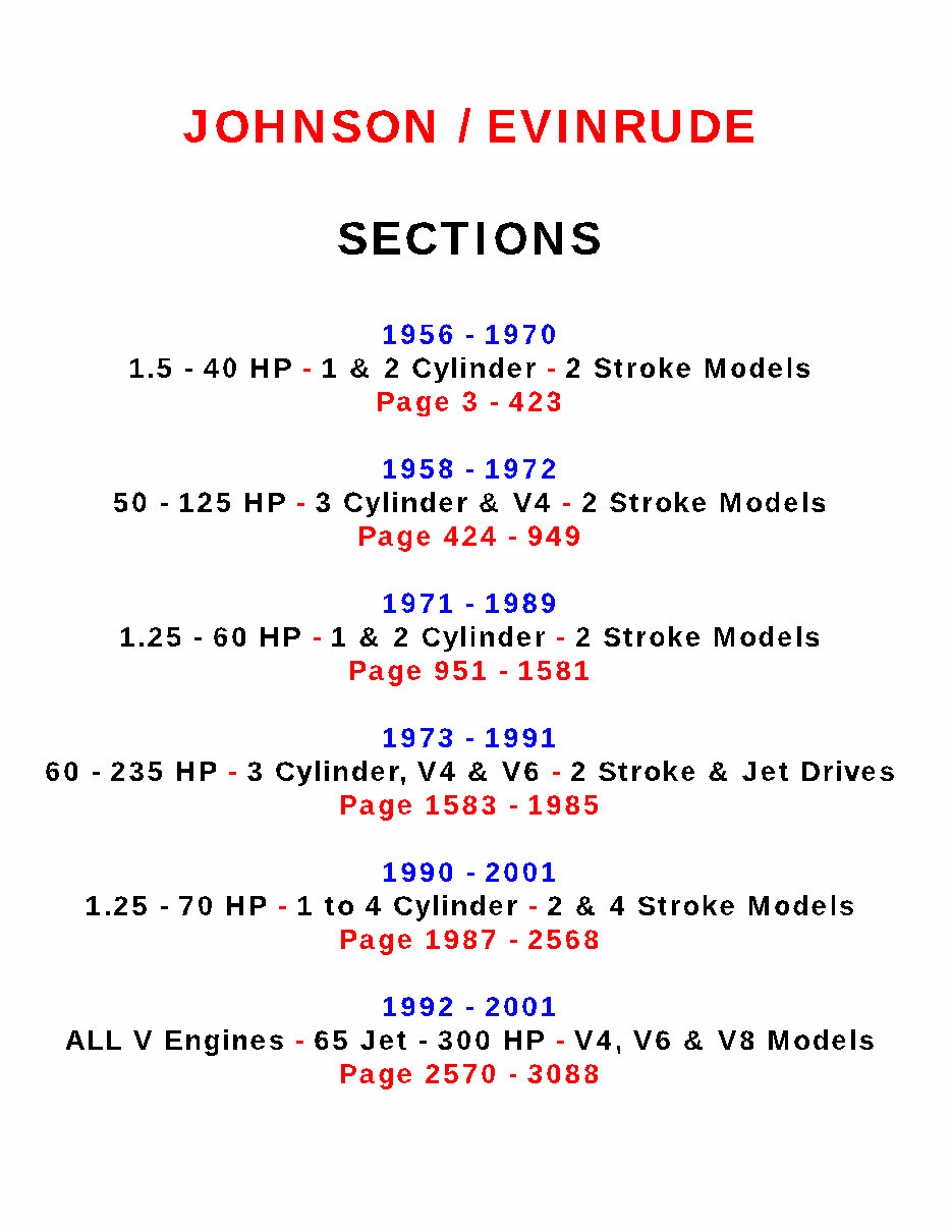
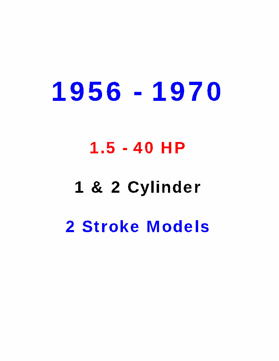
TABLE OF CONTENTS
1 SAFETY
INTRODUCTION
CLEANING, WAXING,
AND POLISHING
CONTROLLING CORROSION
PROPELLERS
FUEL SYSTEM
LOADING
HORSEPOWER
FLOTATION
EMERGENCY EQUIPMENT
COMPASS
STEERING
ANCHORS
MISCELLANEOUS EQUIPMENT
BOATING ACCIDENT REPORTS
NAVIGATION
2 TUNING
INTRODUCTION
TUNE - UP SEQUENCE
COMPRESSION CHECK
SPARK PLUG INSPECTION
IGNITION SYSTEM
SYNCHRONIZING
BATTERY SERVICE
CARBURETOR ADJUSTMENTS
FUEL PUMPS
STARTER AND SOLENOID
INTERNAL WIRING HARNESS
WATER PUMP CHECK
PROPELLER
LOWER UNIT
BOAT TESTING
INTRODUCTION
Theory of Operation
CHAPTER ORGANIZATION
POWERHEAD DISASSEMBLING
HEAD SERVICE
REED SERVICE
Description
Reed Valve Adjustment
Cleaning and Service
BYPASS COVERS
EXHAUST COVER
Cleaning
TOP SEAL
Removal
BOTTOM SEAL
Inspec tion
CENTERING PINS
MAIN BEARING BOLTS
AND CRANKCASE SIDE BOLTS 3 - 15
CRANKCASE COVER 3 - 16
Removal 3 - 16
Cleaning and Inspecting 3 - 16
CONNECTING RODS
AND PISTONS 3 - 16
Removal 3 - 17
Disassembly 3 - 18
Rod Inspection
and Service 3 - 21
Piston and Wing Inspection
and Service 3 - 22
Assembling 3 - 24
CRANKSHAFT 3 - 27
Removal 3 - 27
Cleaning and Inspection 3 - 27
Assembling 3 - 28
CYLINDER BLOCK SERVICE 3 - 28
Honing Procedures 3 - 29
Assembling 3 - 30
Piston and Rod Assembly
Inst allat ion 3 - 30
Crankshaft Installation
Large Horsepower Engines
15 hp to 40 hp 3 - 33
Crankshaft Installation
Small Horsepower Engines
1.5 hp, 5.0 hp, 5.5 hp,
6.0 hp, 9.5 hp 3 - 35
Crankshaft Installation
Small Horsepower Engines
3.0 hp, 4.0 hp, 7.5 hp 3 - 37
Crankcase Cover Installation 3 - 38
Main Bearing Bolt and Crankcase
Side Bolt Installation 3 - 39
Bottom Seal Installation
15 hp to 40 hp Engines 3 - 39
Exhaust Cover and Bypass
Cover Installation 3 - 40
Reed Box Installation 3 - 40
Head Installation 3 - 41
BREAK - IN PROCEDURES 3 - 41
EXPLODED DRAWINGS 3 - 42 - 3 - 50
U DO IT DATA©
4 FUEL
INTRODUCTION
GENERAL CARBURETION
INFORMATION
FUEL SYSTEM
TROUBLESHOOTING
Fuel Pump Tests
Fuel Line Test
Testing with Pressure Tank
Rough Engine Idle
Excessive Fuel Consumption
CARBURETORS
TYPE I CARBURETOR
Removal and Disassembling
Cleaning and Inspecting
Assembling
CHOKE SYSTEM SERVICE
HeatIElectric Choke
All Electric Choke
Water Choke
TYPE I1 CARBURETOR
Disassembling
Cleaning and Inspecting
Assembling
ASSEMBLING CHOKES TO
TYPE 11 CARBURETORS
Adjustments
TYPE 111 CARBURETORS
Removal
Cleaning and Inspecting
Assembling
Adjustments
FUEL PUMP SERVICE
Troubleshooting
Removal and Repair
Cleaning and Inspecting
Assembling and Installation
FUEL TANK AND LINE SERVIC
Disassembling
Cleaning and Inspecting
Assembling
LATE MODEL FUEL TANK
SERVICE
5 IGNITION
INTRODUCTION 5- 1
SPARK PLUG EVALUATION 5 - 2
POLARITY CHECK 5 - 3
WIRING HARNESS 5 - 4
FLYWHEEL MAGNETO IGNITION 5 - 5
TROUBLESHOOTING 5 - 6
SERVICING FLYWHEEL MAGNETO
IGNITION SYSTEM 5- 13
Removal 5- 13
Cleaning and Inspecting 5- 19
Assembling 5 - 20
SYNCHRONIZATION FUEL AND
IGNITION SYSTEMS 5 - 26
Primary Pickup Adjustments
and Locations 5 - 26
6 ELECTRICAL
INTRODUCTION 6 - 1
BATTERIES 6 - 1
Marine Batteries 6 - 1
Battery Construction 6 - 2
Battery Location 6 - 2
Battery Service 6 - 2
Jumper Cables 6 - 5
Dual Battery Installation 6 - 5
GAUGES AND HORNS 6 - 7
Constant - Voltage System 6 - 7
SERVICE PROCEDURES 6 - 7
Temper at ure Gauges 6 - 7
Warning Lights
Thermomelt Sticks 6 - 8
FUEL SYSTEM 6 - 8
Fuel Gauge 6 - 8
Fuel Gauge Hookup 6 - 8
Troubleshooting 6 - 9
TACHOMETER 6 - 10
HORNS 6 - 10
ELECTRICAL SYSTEM GENERAL
INFORMATION 6 - 11
CHARGING CIRCUIT SERVICE 6 - 12
Troubles hooting 6 - 12
Generator Service 6 - 16
Armature Testing 6 - 17
Cleaning and Inspecting 6 - 18
Assembling 6 - 20
CHOKE CIRCUIT SERVICE 6 - 22
STARTER MOTOR CIRCUIT
SERVICE 6 - 22
Circuit Description 6 - 22
Starter Motor Description 6 - 22
Troubleshooting 6 - 24
Testing 6 - 25
STARTER DRIVE GEAR SERVICE 6 - 26
Starter Removal 6 - 26
Drive Gear Disassembling 6 - 27
Cleaning and Inspecting 6 - 27
Assembling Type I Drive 6 - 28
Disassembling Type II 6 - 28
Cleaning and Inspecting 6 - 28
Assembling Type I1 Drive 6 - 28
DEECO-REMY SERVICE 6 - 29
Removal 6 - 29
Disassembling 6 - 29
Armature Testing 6 - 30
Cleaning and Inspecting 6 - 31
Assembling 6 - 32
U DO IT DATA©
6 ELECTRICAL (CONT)
AUTOLITE STARTER MOTOR
SERVICE
Removal
Disassembling
Armature Testing
Cleaning and Inspecting
Assembling
PRESTOLITE STARTER MOTOR
SERVICE
Removal
Disassembling
Armature Testing
Cleaning and Inspecting
Assembling
STARTER MOTOR TESTING
STARTER MOTOR
INSTALLATION
7 ACCESSORIES
INTRODUCTION 7 - 1
SHIFT BOXES 7 - 1
Description 7 - 1
OLD - STYLE DOUBLE LEVER 7 - 3
Troubleshooting 7 - 3
Disassembling 7 - 4
Cleaning and Inspection 7 - 5
Assembling 7 - 5
NEW - STYLE SHIFT LEVER 7 - 6
Troubleshooting 7 - 6
Removal 7 - 8
Disassembling 7 - 8
Cleaning and Inspecting 7 - 9
Assembling 7 - 10
ELECTRIC GEAR BOXES AND
SINGLE LEVER CONTROL 7 - 12
Troubleshooting 7 - 12
Disassembling 7 - 14
Cleaning and Inspecting 7 - 15
Assembling 7 - 16
PUSH BUTTON SHIFT BOX SERVICE
EVINRUDE UNITS ONLY 7 - 18
Troubleshooting 7 - 19
Disassembling 7 - 21
Cleaning and Inspecting 7 - 22
Assembling 7 - 22
CABLE END FITTING INSTALLA -
TION AT THE ENGINE END 7 - 24
8 LOWER UNIT
DESCRIPTION 8 - 1
Chapter Coverage 8 - 1
Illustrations 8 - 2
TROUBLESHOOTING
MANUAL SHIFT 8 - 2
PROPELLER REMOVAL 8 - 7
DRAINING LOWER UNIT
LOWER UNIT SERVICE
1.5 hp to 4.0 hp -- NO SI-IIFT
Lower Unit Removal
Water Pump Removal
Disassembling
Cleaning and Inspecting
Assembling
Water Pump Installation
Lower Unit Installation
Filling the Lower Unit
Propeller Installation
LOWER UNIT SERVICE
MANUAL SHIFT -- 5 HP
TO 25 HP
Removal
Water Pump Removal
Disassembling
Cleaning and Inspecting
Assembling
Water Pump Installation
Lower Unit Installation
LOWER UNIT SERVICE
MANUAL SHIFT -- 28 HP
TO 40 HP 8 - 36
Removal 8 - 37
Water Pump Removal 8 - 38
Disassembling 8 - 38
Cleaning and Inspecting 8 - 41
Assembling 8 - 46
Lower Unit Installation 8 - 50
EEECTROMATIC LOWER UNIT 8 - 53
Description 8 - 53
Troubleshooting 8 - 53
Removal 8 - 56
Disassembling 8 - 57
Cleaning and Inspecting 8 - 65
Assembling 8 - 66
Water Pump Installation 8 - 72
Lower Unit Installation 8 - 74
9 HAND STARTERS
INTRODUCTION 9 - 1
Operation 9 - 2
TYPE I STARTER
CYLINDER WITH PINION GEAR
5 HP and 6 HP ENGINES
9 - 3
Starter Rope Replacement 9 - 4
Removal 9 - 4
Installation 9 - 4
Starter Removal
9 - 5
Disassembling 9 - 7
Cleaning and Inspecting 9 - 7
Assembling 9 - 7 -
U DO IT DATA©
9 HAND STARTERS (CONTI
- TYPE I STARTER
CYLINDER WITH PINION GEAR
ALL 9.5 HP ENGINES 9 - 11
Starter Rope Replacement 9 - 1 1
Removal 9 - 1 1
Installation 9 - 12
Starter Removal 9 - 12
Cleaning and Inspecting 9 - 14
Assembling 9 - 14
Installation 9 - 15
TYPE I1 STARTER
COIL SPRING WITH SWING ARM
DRIVE GEAR
3 HP 1968
4 HP 1969 - 70 9 - 17
Removal 9 - 17
Disassembling 9 - 17
Cleaning and Inspecting 9 - 20
Assembling 9 - 20
TYPE I11 STARTER
MOUNTED ATOP FLYWHEEL
MODEL WITH RETURN SPRINGS
28 HP 1962 - 63
30 HP 1956
35 HP 1957 - 59
40 HP 1960-63 9 - 23
Removal 9 - 24
Cleaning and Inspecting 9 - 26
Assembling 9 - 27
Rope Installation 9 - 29
Starter Installation 9 - 30
TYPE I11 STARTER
MOUNTED ATOP FLYWHEEL
MODEL WITH NO RETURN SPRINGS
28 HP 1964
33 HP 1965 - 70
40 HP 1964 - 70 9 - 31
Removal 9 - 32
Cleaning and Inspecting 9 - 34
Assembling 9 - 34
Rope Installation 9 - 37
Starter Installation 9 - 39
TYPE I11 STARTER
MOUNTED ATOP FLYWHEEL
MODEL WITH ONE NYLON PAWL
3 HP 1956 - 68
5.5 HP 1956 - 64
7.5 HP 1956 - 58
10 HP 1956 - 63
15 HP 1956
18 HP 1956 - 70
20 HP 1966-70
25 HP 1969 - 70 9 - 39
Removal 9 - 40
Disassembling 9 - 40
Cleaning and Inspecting 9 - 42
Assembling 9 - 43
Rope Installation 9 - 43
Starter Installation 9 - 46
10 MAINTENANCE
INTRODUCTION
ENGINE SERIAL NUMBERS
FIBERGLASS HULLS
ALUMINUM HULLS
BELOW WATERLINE SERVICE
SUBMERGED ENGINE SERVICE
WINTER STORAGE
LOWER UNIT SERVICE
Propeller
BATTERY STORAGE
PRESEASON PREPARATION
APPENDIX
METRIC CONVERSION CHART A-1
DRILL SIZE CONVERSION CHART A - 2
TORQUE SPECIFICATIONS A - 3
POWERHEAD SPECS A - 4 & A - 5
TUNE - UP SPECS A - 6 to A10
GEAR OIL CAPACITIES A-11
STARTER MOTOR SPECS A - 12
REGULATOR SPECS A - 12
GENERATOR SPECS A - 12
CONDENSER SPECS A - 13
STARTER ROPE SPECS A - 14
WIRE INDENTIFICATION DRAWINGS
20 hp and 25 hp -- 197 1 - 72 A - 15
33 hp with Generator -- 1965 - 67 A - 16
33 hp with Generator -- 1968 A - 17
33 hp with Generator -- 1969 - 70 A - 18
35 hp - - 1957 - 59 A - 19
40 hp Standard Shift
with Generator -- 1960 - 66 A - 20
40 hp Standard Shift
with Generator -- 1967 - 68 A - 21
40 hp Standard Shift
with Generator -- 1969 - 70 A - 22
40 hp Electric Shift
with Generator - - 1961 - 66 A - 23
40 hp Electric Shift
with Generator -- 1967-68 A - 24
40 hp Electric Shift
with Generator -- 1969 - 70 A - 25
U DO IT DATA©
SAFETY
1 - 1 INTRODUCTION
Your boat probably represents a sizeable
investment for you. In order to protect this
investment and to receive the maximum
amount of enjoyment from your boat it must
be cared for properly while being used and
when it is out of the water. Always store
your boat with the bow higher than the stern
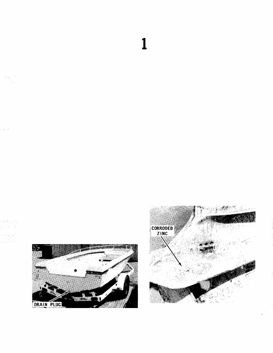
and be sure to remove the transom drain
plug and the inner hull drain plugs. If you
use any type of cover to protect your boat,
plastic, canvas, whatever, be sure to allow
for some movement of air through the hull.
Proper ventilation will assure evaporation of
any condensation that may form due to
changes in temperature and humidity.
1 - 2 CLEANING, WAXING, AND POLISHING
An outboard boat should be washed with
clear water after each use to remove sur -
face dirt and any salt deposits from use in
salt water. Regular rinsing will extend the
time between waxing and polishing. It will
also give you " pride of ownership " , by
having a sharp looking piece of equipment.
Elbow grease, a mild detergent, and a brush
Whenever the boat is stored, for long or short
periods, the bow should be slightly higher than the stern
and the drain plug in the transom removed to ensure
proper drainage of rain water.
will be required to remove stubborn dirt, oil,
and other unsightly deposits.
Stay away from harsh abrasives or strong
chemical cleaners. A white buffing com -
pound can be used to restore the original
gloss to a scratched, dull, or faded area.
The finish of your boat should be thoroughly
cleaned, buffed, and polished at least once
each season. Take care when buffing or
polishing with a marine cleaner not to over -
heat the surface you are working, because
you will burn it.
A small outboard engine mounted on an
aluminum boat should be removed from the
boat and stored separately. Under all cir -
cumstances, any outboard engine must AL -
WAYS be stored with the powerhead higher
than the lower unit and exhaust system.
This position will prevent water trapped in
the lower unit from draining back through
the exhaust ports into the powerhead.
Lower unit badly corroded because the zinc was not
replaced. Once the zinc is destroyed, more costly parts
will be damaged. Attention to the zinc condition is
extremely important during boat operation in salt
water.
U DO IT DATA©
1 - 2 SAFETY
A new zinc prior to installation. This inexpensive
item will save corrosion on more valuable parts.
Most outboard engines have a flat area
on the back side of the powerhead. When
the engine is placed with the flat area on
the powerhead and the lower unit resting on
the floor, the engine will be in the proper
altitude with the powerhead higher than the
lower unit.
1 - 3 CONTROLLING CORROSION
Since man first started out on the water,
corrosion on his craft has been his enemy.
The first form was merely rot in the wood
and then it was rust, followed by other
forms of destructive corrosion in the more
modern materials. One defense against cor -
rosion is to use similar metals throughout
the boat. Even though this is difficult to do
in designing a new boat, particularily the
undersides, similar metals should be used
whenever and wherever possible.
A second defense against corrosion is to
insulate dissimilar metals. This can be done
by using an exterior coating of Sea Skin or
by insulating them with plastic or rubber
gaskets.
Using Zinc
The proper amount of zinc attached to a
boat is extremely important. The use of too
much zinc can cause wood burning by plac -
ing the metals close together and they be -
come "hot". On the other hand, using too
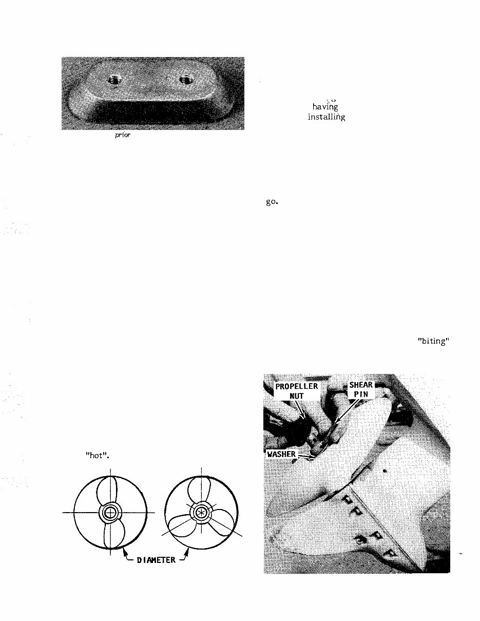
Diameter and pitch are the two basic dimensions of
a propeller. The diameter is measured across the
circumference of a circle scribed by the propeller
blades, as shown.
small a zinc plate will cause more rapid
deterioration of the metal you. are trying to
protect. If in doubt, consider the fact that
is is far better to replace the zincs than to
replace planking or other expensive metal
parts from hav& an excess of zinc.
When installihg zinc plates, there are
two routes available. One is to install many
different zincs on all metal parts and thus
run the risk of wood burning. Another
route, is to use one large zinc on the tran -
som of the boat and then connect this zinc
to every underwater metal part through
internal bonding. Of the two choices, the
one zinc on the transom is the better way to
go*
Small outboard engines have a zinc plate
attached to the cavitation plate. Therefore,
the zinc remains with the engine at all
times.
1 - 4 PROPELLERS
As you know, the propeller is actually
what moves the boat through the water.
This is how it is done. The propeller oper -
ates in water in much the manner as a wood
screw does in wood. The propeller " bites' "
into the water as it rotates. Water passes
between the blades and out to the rear in
the shape of a cone. The propeller "biting"
through the water in much the same manner
as a wood auger is what propels the boat.
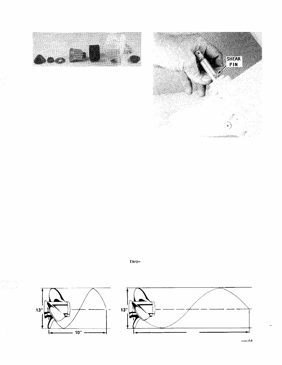
Propeller and associated parts in order, washer,
shear - pin, and nut, ready for installation.
U DO IT DATA©
PROPELLERS 1 - 3
Arrangement of propeller and associated parts, in
order, for a small horsepower engine.
Diameter and Pitch
Only two dimensions of the propeller are
of real interest to the boat owner: the
diameter and the pitch. These two dimen -
sions are stamped on the propeller hub and
always appear in the same order: the diam -
eter first and then the pitch. For instance,
the number 15 - 19 stamped on the hub,
would mean the propeller had a diameter of
15 inches with a pitch of 19.
The diameter is the measured distance
from the tip of one blade to the tip of the
other as shown in the accompanying illus -
tration.
The pitch of a propeller is the angle at
which the blades are attached to the hub.
This figure is expressed in inches of water
travel for each revolution of the propeller.
In our example of a 15 - 19 propeller, the
propeller should travel 19 inches through the
water each time it revolves. If the propel -
ler action was perfect and there was no
slippage, then the pitch multiplied by the
propeller rpms would be the boat speed.
Most outboard manufacturers equip their
units with a standard propeller with a diam -
eter and pitch they consider to be best
suited to the engine and the boat. Such a
propeller allows the engine to run as near to
the rated rpm and horsepower (at full throt -
tle) as possible for the boat design.
The blade area of the propeller deter -
mines its load - carrying capacity. A two-
blade propeller is used for high - speed run -
ning under very light loads.
Shear - pin installed behind the propeller instead of in
front of the propeller.
A four - blade propeller is installed in
boats intended to operate at low speeds
under very heavy loads such as tugs, barges,
or large houseboats. The three - blade pro -
peller is the happy medium covering the
wide range between the high performa'nce
units and the load carrying workhorses.
Propeller Selection
There is no standard propeller that will
do the proper job in very many cases. The
list of sizes and weights of boats is almost
endless. This fact coupled with the many
boat - engine combinations makes the propel -
ler selection for a specific purpose a diffi -
cult job. In fact, in many cases the propel -
ler is changed after a few test runs. Proper
selection is aided through the use of charts
set up for various engines and boats. These
charts should be studied and understood
when buying a propeller. However, bear in
mind, the charts are based on average boats
Diagram to explain the pitch dimension
through the water if there was no slippage.
L_ 21 "
of a propeller. The pitch is the theoretical distance a propeller would
<.
travel
U DO IT DATA©
1 - 4 SAFETY
with average loads, therefore, it may be
necessary to make a change in size or pitch,
in order to obtain the desired results for the
hull design or load condition.
A wide range of pitch is available for
each of the larger horsepower engines. The
choice available for the smaller engines, up
to about 25 hp, is restricted to one or two
sizes. Remember, a low pitch takes a
smaller bite of the water than the high pitch
propeller. This means the low pitch propel -
ler will travel less distance through the
water per revolution. The low pitch will
require less horsepower and will allow the
engine to run faster and more efficiently.
It stands to reason, and it's true, that the
high pitch propeller will require more horse -
power, but will give faster boat speed if the
engine is allowed to turn to its rated rpm.
If a higher - pitched propeller is installed
on a boat, in an effort to get more speed,
extra horsepower will be required. If t h e
extra power is not available, the rpms will
be reduced to a less efficient level and the
actual boat speed will be less than if the
lower - pitched propeller had been left in -
stalled.
All engine manufacturers design their
units to operate with full throttle at, or
slightly above, the rated rpm. If you run
your engine at the rated rpm, you will
increase spark plug life, receive better fuel
economy, and obtain the best performance
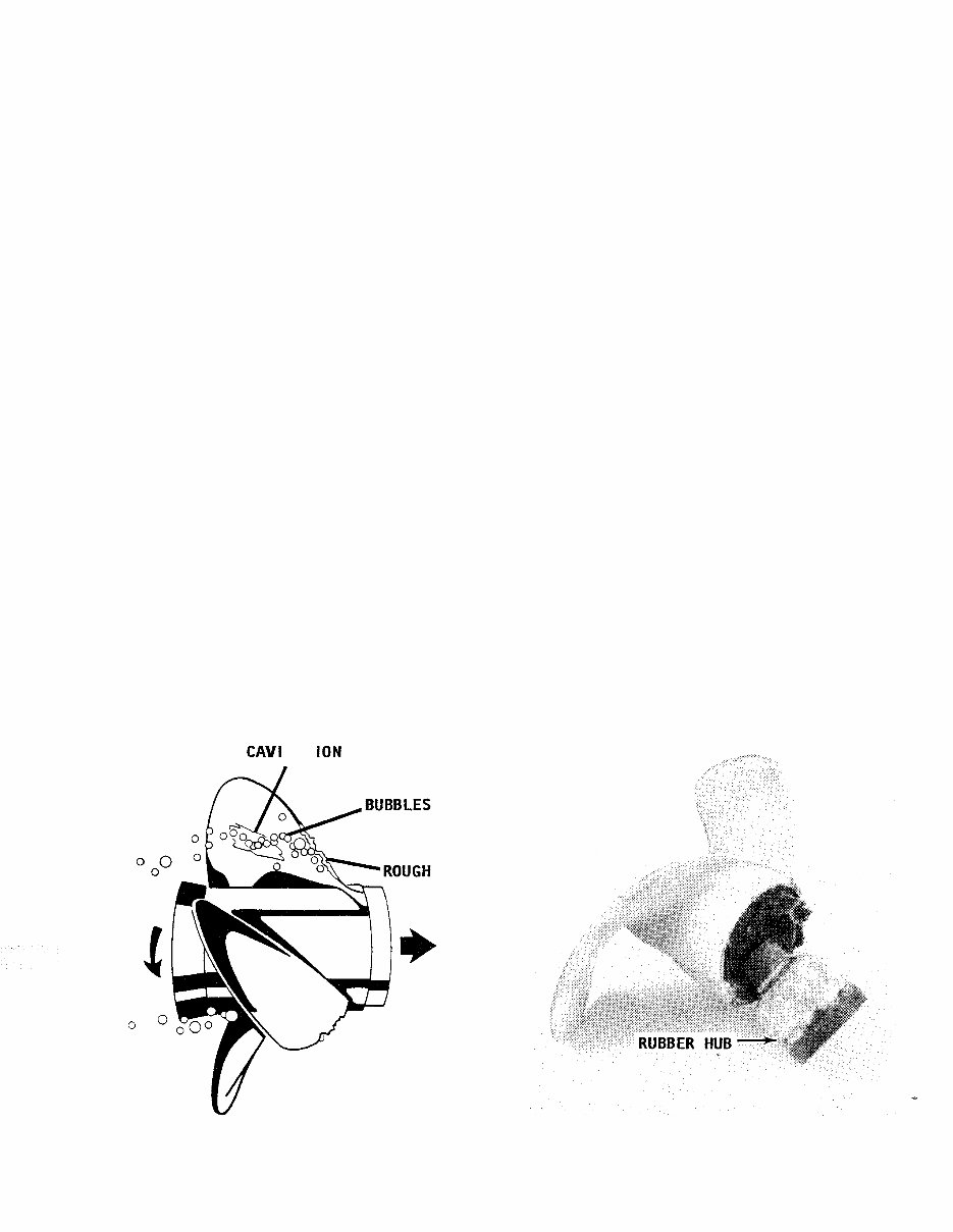
CAVl TAT ION BURN
from your boat and engine. Therefore, take
time to make the proper propeller selection
for the rated rprn of your engine at full
throttle with what you consider to be an
average load. Your boat will then be cor -
rectly balanced between engine and pro -
peller throughout the entire speed range.
A reliable tachometer must be used to
measure engine speed at full throttle to
ensure the engine will achieve full horse -
power and operate efficiently and safely.
To test for the correct propeller, make your
run in a body of smooth water with the
lower unit in forward gear at full throttle.
Observe the tachometer at full throttle.
NEVER run the engine at a high rprn when a
flush attachment is installed. If the reading
is above the manufacturer's recommended
operating range, you must try propellers of
greater pitch, until you find the one that
allows the engine to operate continually
within the recommended full throttle range.
If the engine is unable to deliver top
performance and you feel it is properly
tuned, then the propeller may not be to
blame. Operating conditions have a marked
effect on performance. For instance, an
engine will lose rprn when run in very cold
water. It will also lose rprn when run in salt
water as compared with fresh water. A hot,
low - barometer day will also cause your en -
gine to lose power.
EDGE
Cavitation (air bubbles) formed at the propeller. Example of a damaged propeller. This unit should
Manufacturers are constantly fighting this problem, as have been replaced long before this amount of damage
explained in the text. was sustained.
U DO IT DATA©
You're Reading a Preview
What's Included?
Lifetime Access
Access PDF Contents & Bookmarks
Print one or all pages of your manual