

2002-2006 Johnson Evinrude 40-250HP 2-Stroke Outboards OEM Service & Repair Manual
What's Included?
Fast Download Speeds
Online & Offline Access
Access PDF Contents & Bookmarks
Full Search Facility
Print one or all pages of your manual

This Repair Manual covers All Engines
40-250 HP, 2-Stroke Fuel Injected Models.
Model/Engine Years
40 hp E-Tee, 2 eyl, 2-stroke 2004-2006
50 hp E-Tee, 2 eyl, 2-stroke 2004-2006
60 hp E-Tee, 2 eyl, 2-stroke 2004-2006
70 hp E-Tee, 2 eyl, 2-stroke 2005
75 hp E-Tee, 3 eyl, 2-stroke .2004-2006
90 hp E-Tee, 3 eyl, 2-stroke 2004;2006
200 hp E-Tee, V6, 2-stroke 2005-2006
200 hp E-Tee HO, V6, 2-stroke 2005-2006
225 hp E-Tee, V6, 2-stroke 2005-2006
225 hp E-Tee HO, V6, 2-stroke 2005-2006
250 hp E-Tee, V6, 2-stroke 2005-2006
75 hp FIGHT, V4, 2-stroke . 2002-2003
90 hp FIGHT, V4, 2-stroke 2002-2003
115 hp FIGHT, V4, 2-stroke 2002-2006
135 hp FIGHT, V6, 2-stroke 2002-2006
150 hp FIGH V6, 2-stroke 2002-2006
150 hp FIGHT HO, V6, 2-stroke 2002-2006
175 hp FIGHT, V6, 2-stroke 2002-2006
200 hp FIGHT, V6, 2-stroke 2002-2005
200 hp FIGHT HO, V6, 2-stroke 2002-2005
225 hp FIGHT, V6, 2-stroke 2002-2005
225 hp FIGHT HO, V6, 2-stroke 2002-2005
250 hp FIGHT, V6, 2-stroke 2002-2005
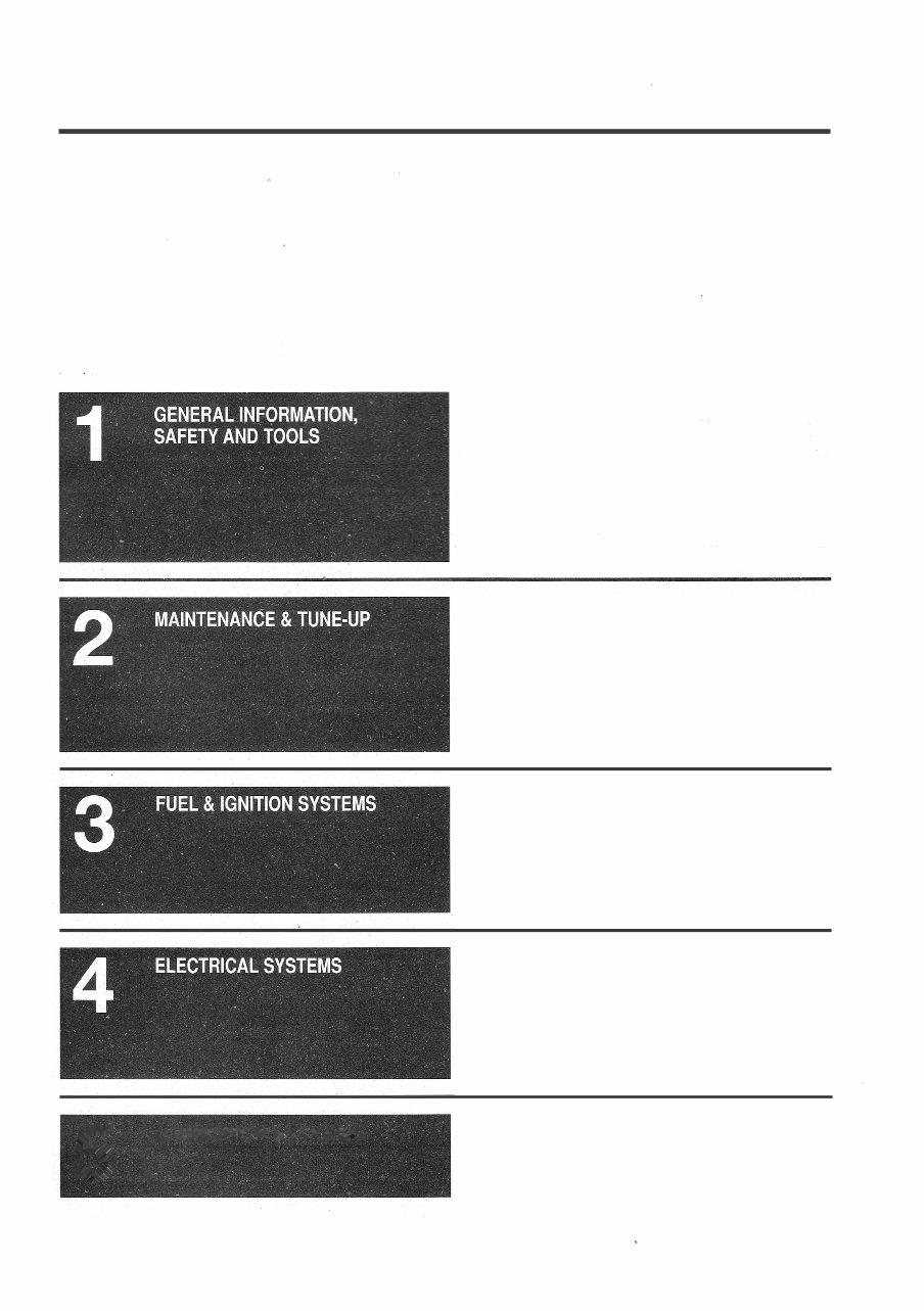
CONTENTS
5
LUB� ICATION & COOLING
- '
HOW TO USE THIS MANUAL 1-2
BOATING SAFETY 1-4
BOATING EQUIPMENT (NOT REQUIRED
BUT RECOMMENDED) 1-10
SAFETY IN SERVICE 1-13
TROUBLESHOOTING 1-13
SHOP EQUIPMENT 1·17
TOOLS 1-19
FASTENERS, MEASUREMENT, AND CONVERSIONS 1-26
SPECIFICATIONS 1·28
GENERAL INFORMATION 2-2
LUBRICATION SERVICE 2-5
ENGINE MAINTENANCE
2-9
BOAT MAINTENANCE 2-26
TUNE-UP 2-30
TIMING AND SYNCHRONIZATION 2-37
STORAGE (WHAT TO DO BEFORE AND AFTER) 2-43
CLEARING A SUBMERGED MOTOR 2-47
SPECIFICATIONS 2-48
FUEL SYSTEM BASICS 3-. 2
FUEL TANK AND LINES 3-6
FICHT FUEL INJECTION (DI/FFI) & IGNITION SYSTEM 3-11
E-TEC FUEL INJECTION & IGNITION SYSTEM 3-54
SPECIFICATIONS 3-92
UNDERSTANDING AND TROUBLESHOOTING
ELECTRICAL SYSTEMS 4-2
CHARGING CIRCUIT 4-8
STARTING CIRCUIT 4-18
WARNING SYSTEM 4-35
WIRING DIAGRAMS 4-38
SPECIFICATIONS 4-60
OIL INJECTION SYSTEM- DI/FICHT MOTORS 5-2
OIL INJECTION SYSTEM - E-TEC MOTORS 5-10
COOLING SYSTEM 5-18
SPECIFICATIONS 5-38
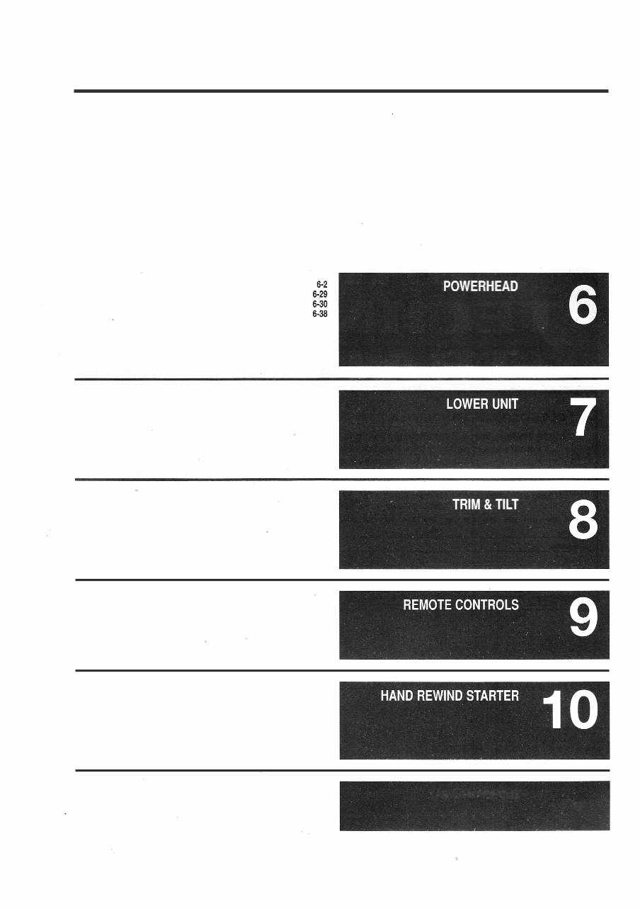
POWERHEAD
POWERHEAD BREAK-IN
POWERHEAD EXPLODED VIEWS
SPECIFICATIONS
GEARCASE
TRIMILT SYSTEMS
REMOTE CONTROLS
CONTROL CABLES
HAND REWIND STARTER
MASTER INDEX
7-2
8-2
9-2
9-16
10-2
10-7
CONTENTS
MASTER INDEX

2-STROKE ENGINE OIL .....................................2-16 FLUSHING THE COOLING SYSTEM .........................2-14
FILLING .................................................2-16 GENERAL INFORMATION .................................. 5-18
FUEL:OIL RATIO........... , .............................. 2-16 PRESSURE RELIEF VALVE .................................5-24
OIL INJECTION...........................................2-17 THERMOSTAT ...........................................5-22
OIL RECOMMENDATIONS .. : .....' .........................2-16 TROUBLESHOOTING THE COOLING SYSTEM ................5-19
PRE-MIX ................................................2-16 WATER PRESSURE CONNECTION (INLINE E-TEC MODELS) ....5-25
40-AMP RELAYS....... : ............ : ...................... 3-54 WATER PUMP AND IMPELLER ... : .......................... 5-25
TESTING & SERVICE .... : ................................ 3-54 COOLING SYSTEM SCHEMATICS ............................5-29
AIR INTAKE SILENCER CRANKSHAFT POSITION SENSOR
E-TEC . . . . . . . . . . . . . . . . . . . . . . . . . . . . . . . . . . . . . . . . . . . . . . . . . . 3-74 AIR GAP ADJUSTMENT ............................. .....2-41
FIGHT ..................................................3-32 E-TEC .................................... ..... : ......... 3-S3
ANODES .................................................2-24 FIGHT .................................................3-41
GENERAL INFORMATION .................................. 2-24 DESCRIPTION & OPERATION
INSPECTION ............................................2-24 COOLING SYSTEM ....................................... 5-18
SERVICE................................................2-25 E-TE FUEL SYSTEM ..................................... 3-54
ANTI-SIPHON VALVE E-TEC OIL SYSTEM .......................................5-10
E-TEC ..................................................3-91 FIGHT FUEL SYSTEM .....................................3-12
FIGHT ..................................................3-51 FIGHT OIL SYSTEM ........................................5-2
BASIC ELECTRICAL THEORY .................................4-2 GEARCASE .............................................. 7-2
HOW DOES ELECTRICITY WORK ............................ 4-2 REMOTE CONTROLS ......................................9-2
OHM'S LAW ..............................................4-2 TRIM/TILT ................................................8-3
BATIERY DUAL HANDLE SURFACE MOUNT REMOTE (SINGLE MOTORS) ....9-8
BAERY CABLES ........................................4-17 OVERHAUL. . . . . . . . . . . . . . . . . . . . . . . . . . . . . · . . . . . . . . . . . . . . . . . 9-8
CHARGERS . . . . . . . . . . . . . . . . . . . . . . . . · . . . . : ................4-17 E-TEC FUEL INJECTION & IGNITION SYSTEM .. . . .. . . . .... . ... 3-54
CONSTRUCTION . . . . . . . . . . . . . . . . . . . . . . . . . . · . . . . . . . . . . . . . . . 4-16 AIR INTAKE SILENCER ....................................3-74
GENERAL INFORMATION .................................. 4-15 . ANTI-SIPHON VALVE ...................................... 3-91
GENERAL INFORMATION ..................................2-26 CAPACITOR ....................................... , ....3-91 .
LOCATION .............................................. 4-16 CIRCULION PUMP ......................................3-79
MAiNTENANCE ............................ : ............. 2-27 COMPONENT TESTING ...................................3-67
MARINE BATIERIES ......................................4-16 CRANKSHAFT POSITION SENSOR .......................... 3-83
RATINGS................................................4-16 DESCRIPTION AND OPERATION ............................3-54
SAFETY PRECAUTIONS ...................................4-16 EMM PIN-OUTS/CIRCUIT CHECKS ..........................3-66
SERVICE................................................4-17
STORAGE ................ : ..............................2-29
ENGINE MANAGEMENT MODULE (EMM) .....................3-90
ENGINE SYMPTOM DIAGNOSTIC CHARTS ...................3-63
TESTING .. . . . . . · . . . . . . . . . . . . . . . . . . . . . . . . . . . . . . . . . . . . . . . . . 2-28 FLAME ARRESTER .......................................3-74
BOAT MAINTENANCE . ......... . .... . .. . . . .... . .. . .... . .... 2-26 . FUEL FILTER WATER SENSOR ............................. 3-91
BAERIES..............................................2-26 FUEL INJECTORS ........................................3-80
FIBERGLASS HULL . . . . . . . . . . . . . . . . . . . . ... . . .. . . . . . _ . ... . . 2-29 FUEL PRESSURE REGULATOR .............................3-91
BOATING EQUIPMENT (NOT RE UIRED BUT RECOMMENDED) . . 1-10 FUEL RAILS .............................................3-82
ANCHORS ............................................ :.1-10 GENERAL INFORMATION ..................................3-54
BAILING DEVICES ........................................1-10 IGNITION COILS .........................................3-87
COMPASS ...............................................1-11 ISOLATING PROBLEMS WITH THE E-TEC SYSTEM ............3-58
FIRST AID KIT ...........................................1-10 LIFT PUMP .............................................. 3-76
OAR/PADDLE (SECOND MEANS OF PROPULSION) ............1-10 PRESSURE SENSOR .....................................3-90
TOOLS AND SPARE PARTS ................................ 1-12 SELF-DIAGNOSTIC SYSTEM ...............................3-59
VHF-FM RADIO ..........................................1-10 SHIFT INTERRUPT SWITCH ................................ 3-89
BOATING SAFETY .. . .... . . . . ........... . .. . ................ 1-4 TEMPERATURE SENSORS/SWITCHES....................... 3-84
COURTESY MARINE EXAMINATIONS ......................... 1 �10 THROLE BODY ........................................ 3-75
REGULATIONS FOR YOUR BOAT ............................1-4 THROTILE POSITION SENSOR .............................3-86
REQUIRED SAFETY EQUIPMENT ........... : ................ 1-5 TROUBLESHOOTING .....................................3-57
FIRE EXTINGUISHERS .....................................1-6 VST ASSEMBLY ................. .' ....................... 3-79
PERSONAL FLOTATION DEVICES ............................ 1-7 ELECTRIC STARTER MOTOR PINION ..........................2-5
SOUND PRODUCING DEVICES ..............................1-8 LUBRICATION ............................................2-6
TYPES OF FIRES .......................................... 1-5 RECOMMENDED LUBRICANT ............................... 2-5
VISUAL DISTRESS SIGNALS................................1-8 EMM PIN-OUTS/CIRCUIT CHECKS
WARNING SYSTEM ...........
.
......... , ..................1-7 E-TEC ..................................................3-66
CAPACITOR FIGHT ..................................................3-23
E-TEC .................................................. 3-91 ENGINE COVER LATCHES ...................................2-6
FIGHT .................................................. 3-53 LUBRICATION ............................................2-6
CHARGING CIRCUIT . . . ...... . ... . . . ................ . ....... 4-8 RECOMMENDED LUBRICANT ...............................2-6
BATIERY ............................................... 4-15 ENGINE COVERS ........................................... 2-9
GENERAL INFORMATION ...................................4-8 REMOVAL & INSTALLATION .................................2-9
SERVICE PRECAUTIONS ...................................4-9 ENGINE IDENTIFICATION ....................................2-1
STATOR/BATIERY CHARGE COIL ...........................4-12 ENGINE MODEL NUMBERS .................................2-3
TROUBLESHOOTING ................................ .' .....4-9 GENERAL INFORMATION ...................................2-1
CLEARING A SUBMERGED MOTOR ... . ...................... 2-47 ENGINE MAINTENANCE ...... . . .... . ... , .................... 2-9
COMPRESSION CHECK .................................... 2-31 2-STROKE ENGINE OIL....................................2-16
CONCEALED SIDE MOUNT REMOTE ..........................9-9 ANODES (ZINCS) .........................................2-24
OVERHAUL...............................................9-9 COOLING SYSTEM .......................................2-14
CONTROL CABLES ENGINE COVERS .........................................2-9
ADJUSTMENT ........................................... 2-39 EXHAUST PRESSURE FITIING .............................2-26
RIGGING ................................................9-16 FUEL FILTER ............................................2-19
COOLING SYSTEM LOWER UNIT (GEARCASE) OIL ......... : ...................2-17
COOLING SYSTEM SCHEMATICS ...........................5-29 OIL FILTER ..............................................2-26
DESCRIPTION AND OPERATION ............................5-18 PROPELLER.............................................2-22

ENGINE MANAGEMENT MODULE (EMM)
E-TEC .................................................. 3-90
FIGHT .................................................. 3-50
ENGINE SYMPTOM DIAGNOSTIC CHARTS
E-TEC .. ' ................................................ 3-63
FICHT . . . . . . . . . .. . . . . . . . . . . . . . . . . . . . . . . . . . . . . . . . . . . . � . . . . 3-19
ENGINE TEMPERATURE SENSORS/SWITCHES ................ 4-37
EXHAUST PRESSURE FITTING .............................. 2-26
GENERAL INFORMATION .................................. 2-26
INSPECTON & SERVICE ................................... 2-26
EXPLODED VIEWS
GEARCASE ............................................. 7-20
POWERHEAD ............................................ 6-30
FASTENERS, MEASUREMENTS AND CONVERSIONS . . . . . . . . . . . 1·27
BOLTS, NUTS AND OTHER THREADED RETAINERS ........... 1-27
STANDARD AND METRIC MEASUREMENTS .................. 1-27
TORQUE ................................................ 1-27
FIBERGLASS HULL ............. : .......................... 2-29
INSPECTION AND CARE ................................... 2-29
FFI MAIN SYSTEM RELAY ....................... , ........... 3-53
GENERAL INFORMATION.................................. 3-53
TESTING & SERVICE ..................................... ·3-53
FICHT FUEL INJECTION (OliFF!) & IGNITION SYSTEM . . . . . . . . . . . 3·11
40-AMP RELAYS ......................................... 3-54
AIR INTAKE SILENCER .................................... 3-32
ANTI-SIPHON VALVE ...................................... 3-51
CAPACITOR ............................................. 3-53
CIRCULATION PUMP ...................................... 3-37
CRANKSHAFT POSITION SENSOR .......................... 3-41
DESCRIPTION & OPERATION .............................. 3-12
EMM PIN-OUTS/CIRCUIT CHECKS .......................... 3-23
ENGINE MANAGEMENT MODULE (EMM) ..................... 3-50
ENGINE SYMPTOM DIAGNOSTIC CHARTS ................... 3-19
FFI MAIN SYSTEM RELAY ................................. 3-53
FIGHT COMPONENT TESTING .............................. 3-25
FILTER MODULE ......................................... 3-52
-
FLAME ARRESTER ................................. : ..... 3-32
FUEL FILTER WATER SENSOR ............................. 3-52
FUEL INJECTORS ........................................ 3-39
FUEL MANIFOLDS & LINES ................................ 3-41
FUEL PRESSURE REGULATOR . . . . . . . . . . . . . . . . . . . . . · . . ... . . . 3-51
GENERAL INFORMATION . . . . . . . . . . . . . . . . . . � . . . . . . . . . . . . . . . 3-11.
IGNITION COILS ......................................... 3-46
ISOLATING PROBLEMS ................................... 3-16
LIFT PUMP .............................................. 3-34
PRESSURE SENSOR ..................................... 3-49
SYSTEM IDENTIFICATION ................................. 3-11
SELF-DIAGNOSTIC SYSTEM ............................... 3-17
SHIFT INTERRUPT SWITCH ........... , .................... 3-49
TEMPERATURE SENSORS/SWITCHES ..................... :. 3-43
THROTTLE BODY . . . . . . . . . . . . . � . . . . . . . . . . . . . . . . . . . . . . . . . . 3-33
THROTTLE POSITION SENSOR ............................. 3-45
TROUBLESHOOTING ........ : ............................ 3-14
VST ASSEMBLY................................... ; ...... 3-37
FILTER MODULE .......................................... 3-52
GENERAL INFORMATION & TESTING ...............
-
....... 3-52
FLAME ARRESTER
.
. E-TEC .................................................. 3-74
FIGHT .................................................. 3-32
FLYWHEEL ................................................ 6-3
REMOVAL & INSTALLATION ................................. 6-3
FLYWHEEL COVER ......................................... 6-2
REMOVAL & INSTALLATfON ................................. 6-2
FUEL . . . . . . . . . . . . . . . . . . . . . . . . . . . . . . . . . . . . . . . . . . . . . . . . . . . . . 3-2
ALCOHOL-BLENDED FUELS . . . . . . . . . . . . . . . . . . . . . · . . . . . . . . . . . 3-3
CHECKING FOR STALE/CONTAMINATED FUEL ................. 3-3
FUEL SYSTEM PRESSURIZATION............................ 3-4
GENERAL................................................ 3-2
HIGH ALTITUDE OPERATION ................................ 3-3
OCTANE RATING .......................................... 3-3
RECOMMENDATIONS .................................. : ... 3-3
RELIEVING FUEL SYSTEM PRESSURE ....................... 3-5
VAPOR PRESSURE........................................ 3-3
FUEL FILTER ............................................. 2-19
FUEL FILTER REPLACMENT ............................... 2-20
FUEL SYSTEM PRESSURE ................................ 2-19
GENERAL INFORMATION .................................. 2-19
FUEL FILTER WATER SENSOR
E-TEC .................................................. 3-91
FIGHT .................................................. 3-52
FUEL INJECTORS
E-TEC .................................................. �80
FIGHT ............................................... : .. 3-39
FUEL LINES AND FITTINGS .................................. 3-8
GENERAL INFORMATION ................................... 3-8
SERVICE ................................................ 3-10
TESTING ................................................. 3-9
FUEL MANIFOLDS AND FUEL LINES - FIGHT
.
REMOVAL & INSTALLATION ................................ 3-41
FUEL PRESSURE REGULATOR
E-TEC .................................................. 3-91
FIGHT . . . . . .· . . . . . . . . . . . . . . . . . . . . . . . . . . . . . . . . . . . . . . . . . . . . 3-51
FUEL RAILS .............................................. 3-82
REMOVAL & INSTALLATION ................................ 3-82
FUEL SYSTEM BASICS . . . . . . . . . . . . . . . . . . . . . . . . . . . . . . . . . . . . . . 3·2
FUEL .................................................... 3-2
FUEL SYSTEM PRESSURIZATION............................ 3-4
FUEL SYSTEM SERVICE CAUTIONS .......................... 3-2
GENERAL INFORMATION ................................... 3-2
FUEL SYSTEM SERVICE CAUTIONS . . . . . . . . . . . . · . . . . . . . . . . . . . . . 3-2
FUEL TANK................................................ 3-6
GENERAL INFORMATION................................... 3-6
SERVICE ................................................. 3-7
FUEL TANK AND LINES . . . . . . . . . . . . . . . . . . . . . . . . . . . . . . . . . . . . . 3·6
FUEL LINES AND FITTINGS ................................. 3-8
FUEL TANK . . . · . . . . . . . . . . . . . . . . . . . . . . . . . . . . . . . . . . . . . . . . . . . . 3-6
GENERAL INFORMATION................................... 3-6
GEARCASE . . . . . . . . . . . . : . . . . . . . . . . . . . . . . . . . . . · . . . . . . . . . . . . . 7-2
DESCRIPTION AND OPERATION ............................. 7-2
GEARCASE ASSEMBLY -·40-70 HP (2-CYLINDER) MODELS ....... 7-5
GEARCASE ASSEMBLY - 75 HP AND LARGER (L3, V4 AND V6)
MODELS ................................................ 7-17
GENERAL INFORMATION . . . . . . . . . . . ' . . . . . . . . . . . . . . . . . . . . . . 7-2
PROPELLER SHAFT SEAL ................................. 7-38
TROUBLESHOOTING ...................................... 7-3
GEARCASE ASSEMBLY - 40-70 HP (2-CYL) ..................... 7-5
ASSEMBLY.............................................. 7-14
CLEANING & INSPECTION ............ : .................... 7-12
DISASSEMBLY ............................................ 7-7
DRIVESHAFT BEARING HOUSING .......................... 7-12
DRIVESHAFT SHIMMING .................................. 7-13
PRESSURE TESTING ..................................... 7-16
PROPELLER SHAFT BEARING HOUSING..................... 7-11
REMOVAL & INSTALLATION . . . . . . . . . � . . . . . . . . . . . . . . . . . . . . . . . 7-5
SHIFT ROD HEIGHT ADJUSTMENT .......................... 7-16
GEARCASE ASSEMBLY - 75 HP & LARGER (L3, V4 AND V6) ...... 7-17
ASSEMBLY . . . . . . . . . . . . . . . . . . . . . . . . · . . . . . . . . . . . . . . . . . . . . . · . . 7-29
CLEANING & INSPECTION ................................. 7-28
DISASSEMBLY ........................................... 7-20
FUNCTIONAL CHECK . . . . . . . . . . . . . . . . . . . . . . . . . . � . . . . . . . . . . 7-38
REMOVAL & INSTALLATION ................................ 7-17
GENERAL INFORMATION . . . . . . . . . . . . . . . . . . . . . . . . . . . . . . . . . . . . 2·1
BEFORE/AFTER EACH USE ................................. 2-4
ENGINE IDENTIFICATION....... - ............................ 2-1
GENERAL INFORMATION................................... 2-1
MAINTENANCE COVERAGE ................................. 2-1
MAINTENANCE EQUALS SAFETY ............................ 2-1
HAND REWIND STARTER . . . . . . . . . . . . . . . . . . . . . . . . . . . . . . . . . . . 10·2
MANUAL STARTER ASSEMBLY ............................. 10-2
HIGH PRESSURE FUEL PUMP (CIRCULION PUMP)
E-TEC .................................................. 3-79
FIGHT .................................................. 3-37
HOW TO USE THIS MANUAL . . . . . . . . . . . . . . . . . . . . . . . . . . . . . . . . . 1·2
AVOIDING THE MOST COMMON MISTAKES ................... 1-3
AVOIDING TROUBLE ....................................... 1-2
CAN YOU DO IT? .......................................... 1-2
DIRECTIONS AND LOCATIONS .............................. 1-2
MAINTENANCE OR REPAIR? ................................ 1-2
PROFESSIONAL HELP . . . . . . . . . . . . . . . . . . . . . . . . . . . . . . . . . � . . . 1-3
PURCHASING PARTS ...................................... 1-3

WHERE TO BEGIN ......................................... 1-2
IGNITION COILS
E-TEC ........... ...................................... 3-87
FIGHT . . . . . . . . . . . . . . . . . . . � . . . . . . . . . . . . . . . . . . . . . . . . . . . . . . 3-46
IGNITION TIMING
CHECKING .............................................. 2-43
IMPELLER .......................................... : ..... 5-25
GENERAL INFORMATION .................................. 5-25
INSPECTION & OVERHAUL ................................ 5-29
REMOVAL & INSTALLATION................................ 5-25
INTAKE MANIFOLD AND LEAF VALVE......................... 6-27
REMOVAL, INSPECTION & INSTALLATION .................... 6-27
LINKAGE, CABLES AND SHAFTS .............................. 2-7
LUBRICATION ............................................ 2-7
RECOMMENDED LUBRICANT ............................... 2-7
LOW PRESSURE FUEL PUMP (LIFT PUMP)
.
E-TEC.................................................. 3-76
FIGHT .................................................. 3-34
LOWER UNIT (GEARCASE) OIL .............................. 2-17
CHECKING OIL LEVEL & CONDITION........................ 2-17
DRAINING AND FILLING................................... 2-1 g
GENERAL INFORMATION .................................. 2-17
OIL RECOMMENDATIONS ................................. 2-17
LUBRICATION SERVICE . . . . . . . . . . . . . . . . . . . . . . . . . . . . . . . . . . . . . 2·5
ELECTRIC STARTER MOTOR PINION ......................... 2-5
ENGINE COVER LATCHES .................................. 2-6
GENERAL INFORMATION................................... 2-5
LINKAGE, CABLES AND SHAFTS ............................. 2-7
POWER TRIM!TILT RESERVOIR .............................. 2-6
STEERING ARM ........................................... 2-8
SWIVEL BRACKET AND TILT SUPPORT ....................... 2-8
TILT TUBE ASSEMBLY ...................................... 2-9
MANUAL STARTER ASSEMBLY .............................. 10-2
DISASSEMBLY & A SSEMBLY............................... 10-4
GENERAL INFORMATION .............. - .................... 10-2
MANUAL STARTER SERVICE ............................... 10-2
REMOVAL & INSTALLATION . . . . . . . . . . . . . � . . . . . . . . . . . . . . . . . . 10-2
OIL COMPONENT ASSEMBLY
E-TEC.................................................. 5-15
FIGHT . . . . . . . . . . . . . . . . . . . . . . . . . . . . . . . . . . . . . . . . . . . . . . . . . . . 5-7
OIL FILTER ............................................... 2-26
GENERAL INFORMATION .................................. 2-26
INSPECTON & SERVICE ............................. : ..... 2-26
OIL INJECTION SYSTEM · DI/FICHT . . . . . . . . . . . . . . . . . . . . . . . . . . . 5·2
DESCRIPTION AND OPERATION ............................. 5-2
GENERAL INFORMATION ................................... 5-2
OIL COMPONENT ASSEMBLY ............................... 5-7
OIL RECIRCULATION SYSTEM DIAGRAMS .................... 5-9
TROUBLESHOOTING .................................. : ... 5-3
OIL INJECTION SYSTEM· E-TEC . . . . . . . . . . . . . . . . . . . . . . . . . . . . 5-10
DESCRIPTION AND OPERATION ............................ 5-10
GENERAL INFORMATION .................................. 5-1 o.
OIL COMPONENT ASSEMBLY .............................. 5-15
OIL RECIRCULATION SYSTEM DIAGRAMS ................... 5-17
TROUBLESHOOTING ..................................... 5-11
OIL RECIRCULATION SYSTEM DIAGRAMS _
E-TEC.......................' ........................... 5-17
FIGHT ................................................... 5-9
POWER TRIM!TILT RESERVOIR ............................... 2-6
CHECKING FLUID LEVEUCONDITION ........................ 2-7
RECOMMENDED LUBRICANT ............................... 2-6
POWERHEAD .............................................. 6-5
ASSEMBLY .............................................. 6-14
CLEANING & INSPECTION ................................. 6-20
DISASSEMBLY ........................................... 6-10
REMOVAL & INSTALLATION................................. 6-5
POWERHEAD . . . . . . . . . . . . . . . . . . . . . . . . . . . . . . . . . . . . . . . . . . . . . . 6-2
FLYWHEEL ............................................... 6-3
FLYWHEEL COVER ........................................ 6-2
GENERAL INFORMATION .............................. ' ..... 6-2
INTAKE MANIFOLD & LEAF VALVE .......................... 6-27
POWER HEAD ............................................. 6-5
POWERHEAD BREAK-IN . . . . . . . . . . . . . . . . . . . . . . . . . . . . . . . . . . . 6·29
GENERAL INFORMATION .................................. 6-29
POWERHEAD EXPLODED VIEWS . . . . . . . . . . . . . . . . . . . . . . . . . . . . 6-30
PRE-WIRED BINNACLE MOUNT REMOTE ..................... 9-12
OVERHAUL .............................................. 9-12
PRESSURE RELIEF VALVE .................................. 5-24
REMOVAL & INSTALLATION................................ 5-24
PRESSURE (EP AND BP) SENSOR
E-TEC.................................................. 3-90
FIGHT . . . . . . . . . . . . . . . . . . . . . . . . . . . . . . . . . . . . . . � . . . . . . . . . . 3-49
PROPELLER .................................... - .......... 2-22
GENERAL INFORMATION.................................. 2-22
INSPECTION ............................................ 2-22
REMOVAL & INSTALLATION................................ 2-23
PROPELLER SHAFT SEAL .................................. 7-38
GENERAL INFORMATION.................................. 7-38
REPLACEMENT.......................................... 7-38
RE-COMMISSIONING ...................................... 2-46
REMOTE CONTROLS . . . . . . . . . . . . . . . . . . . . . . . . . . . . . . . . . . . . . . . 9·2
CONCEALED SIDE MOUNT REMOTE UNITS................... 9-9
DESCRIPTION AND OPERATION ................. : ........... 9-2
DUAL HANDLE SURFACE MOUNT REMOTE UNITS FOR SINGLE
MOTORS ...... : .......................................... 9-8
INTRODUCTION ........................................... 9-2
PRE-WIRED BINNACLE MOUNT REMOTE UNITS . . . . . . . . . . . . . .
��
SMALL MOTOR STANDARD SURFACE REMOTE UNITS . . . . . . . . • ,� ·6
STANDARD SURFACE MOUNT REMOTE UNITS . . . . . . . . . . . . . . · -3
SAFETY IN SERVICE . . . . . . . . . . . . . . . . . . . . . . . . . . . . . . . . . . . . . . . -
-
13
DO'S ................................................... 1-13
DON'TS ................................................. 1-13
SELF-DIAGNOSTIC SYSTEM - E-TEC ......................... 3-59
LED DIAGNOSTICS....................................... 3-59
TROUBLE CODES........................................ 3-60
SELF-DIAGNOSTIC SYSTEM - FIGHT . . . . . . . . . . . . . . . . . . . . . . _ . . . 3-17
TROUBLE CODES ...................................... 3-17
READING CODES ....................................... 3-17
MANUALLY CLEARING CODES ............................ 3-19
SHIFT INTERRUPT SWITCH
.
E- TEC . . . . . . . . . . . . . . . . . . . . . . . . . . . . . . . . . . . . . . . .•. . . . . . . . . . 3-89
FIGHT . . . . . . . . . . . . . . . . . . . . . . . . . . . . · . . . . . . . . . . . . . . . . . . . . . . 3-49
SHOP EQUIPMENT . . . . . . . . . . . . . . . . . . . . . . . . . . . . . . . . . . . . . . . . 1·17
CHEMICALS ............................................. 1-17
SAFETY TOOLS .......................................... 1-17
SMALL MOTOR STANDARD SURFACE REMOTE ................. 9-6
OVERHAUL ............................................... 9-6
· SPARK PLUG WIRES ....................................... 2-36
REMOVAL & INSTALLATION._ .......................... : ... 2-37
TESTING ................................................ 2-36
SPARK PLUGS . . . . . . . . . . . . . . . . . . . . . . . . . . . . . . . . . . . . . . 1 . . . • . 2-32
GENERAL INFORMATION .................................. 2-32
INSPECTION & GAPPING .................................. 2-36
HEAT RANGE............................................ 2-32
READING SPARK PLUGS . . . . . . . . . . . . . . · . . . . . . . . . . . . . . . . . . . . 2-34
REMOVAL & INSTALLATION ................................ 2-32
SPECIFICATIONS
CAPACITIES ............................................. 2-52
CONVERSION FACTORS .................................. 1-28
COOLING SYSTEM ....................................... 5-38
ENGINE - 40-90 HP 2/3-CYL E-TEC .......................... 6-38
ENGINE - 75-115 HP DI/FICHT V4 ........................... 6-39
ENGINE - 135-175 HP DI/FICHT V6 .......................... 6-39
ENGINE - 200-250 HP DI/FICHT & E-TEC V6 ................... 6-40
GENERAL ENGINE ............ , .......................... 2-49
GENERAL ENGINE SYSTEM ............................... 2-49
IGNITION & INJECTOR SENSOR TESTING .................... 3-92
LUBRICATION SERVICES .................................. 2-51
MAINTENANCE INTERVALS
METRIC BOLTS - TYPICAL TORQUE VALUES ................. 1-30
SPARK PLUG DIAGNOSIS ............................... : . 2-54
STATOR TESTING ........................................ 4-60
TUNE-UP ............................................... 2-53
TWO-STROKE MOTOR FUEL:OIL RATIO ...................... 2-48
U.S. STANDARD BOLTS - TYPICAL TORQUE VALUES .......... 1-29
STANDARD SURFACE MOUNT REMOTE ....................... 9-3
OVERHAUL ............................................... 9-3
START CIRCUIT SWITCHES................................. 4-22
STARTER MOTOR ......................................... 4-24
CLEANING & INSPECTION ................................. 4-32

GENERAL INFORMATION.................................. 4-24 REMOVAL & INSTALLATION ................................. 8-13
REMOVAL & INSTALLATION ................................ 4-26 TRIM/TILT SYSTEMS . . . . . . . . . . . . . . . . . . . . . . . . . . . . . . . . . . . . . . . . 8·2
OVERHAUL .............................................. 4-27 DESCRIPTION & OPERATION ............................... 8-3
STARTER MOTOR SOLENOID/RELAY SWITCH . . . . � . . . . . . . . . . . . 4-34
INTRODUCTION . . . . . . . . . . .. . . . . . . . . . . . . . . . . . . . . . . . . . � . . . . . 8-2
GENERAL INFORMATION .................................. 4-34
SYSTEM IDENTIFICATION .................................. 8-2
REMOVAL & INSTALLATION ................................ 4-35
TILT LIMIT SWITCH ....................................... 8-10
TESTING THE SOLENOID .................................. 4-34
TRIM SENDING UNIT ...................................... 8-11
STARTING CIRCUIT . . . . . . . . . . . . . . . . . . . . . . . . . . . . . . . . . . . . . . . . 4·18
DI/FICHT STARTER CIRCUIT ............................... 4-19
E-TEC STARTER CIRCUIT ................................. 4-21
ELECTRIC STARTER BASICS . . . . . . . . . . . . . . . . . . .
.
· . . . . . . . . . . . 4-18
START CIRCUIT SWITCHES ................................ 4-22
STARTER MOTOR . . . . A • • • • • • • • • • • • • • • • • • • • • • • • • • • • • • • • • • • 4-24
STARTER MOTOR SOLENOID/RELAY SWITCH ................ 4-34
STATOR/BATTERY CHARGE COIL ............................ 4-12
TRIM/TILT ASSEMBLY -1-RAM .............................. 8-12
TRIM/TILT ASSEMBLY -3-RAM .............................. 8-13
TROUBLESHOOTING ...................................... 8-5
TROUBLESHOOTING
2-STROKE MOTORS ...................................... 1-14
4-STROKE MOTORS ...................................... 1-16
BASIC OPERATING PRINCIPLES.. , ............ : ............ 1-13
CHARGING SYSTEM....................................... 4-9
COMBUSTION ........................................... 1-16
GENERAL INFORMATION .................................. 4-12
COOLING SYSTEM ....................................... 5-19
REMOVING & INSTALLATION ............................... 4-15
E-TEC FUEL SYSTEM ..................................... 3-57
STEERING ARM ............................................ 2-8
E-TEC OIL SYSTEM....................................... 5-11
LUBRICATION ............................................ 2-8
ELECTRICAL SYSTEMS .................................... 4-6
RECOMMENDED LUBRICANT ............................... 2-8
FIGHT FUEL SYSTEM ..................................... 3-14
STORAGE (WHAT TO DO BEFORE AND AFTER) . . . . . . . . . . . . . . . . 2·43 FIGHT OIL SYSTEM........................................ 5-3
RE-COMMISSIONING ..................................... 2-46 GEARCASE .............................................. 7-3
WINTERIZATION ......................................... 2-43 TRIM/TILT . . . . . . .. . . . . . . . . . ·. . . . . . . . . . . . . . . . . . . . . . . . . . . . . . . 8-5
SWIVEL BRACKET AND TILT SUPPORT ........................ 2-8 WARNING SYSTEM ....................................... 4-36
LUBRICATION ................................ : ........... 2-8
TUNE-UP . . . . . . . . . . . . . . . . . . . . . . . . . . . . . . . . . . . . . . . . . . . . . . . . . 2·30
RECOMMENDED LUBRICANT ............................... 2-8
T. EMPERATURE SENSORS/SWITCHES
E-TEC ................................................. 3-84
FICHT .................................................. 3-43
THERMOSTAT . . . . . . . . . . . . . . . . . . . . . . . . . . . . . . . · . . .. . . . . . . . . . 5-22
GENERAL INFORMATION . .· . . . . . . . . . . . . . . . . . . . . . . . . . . . . . . . . 5-22
REMOVAL & INSTALLATION ................................ 5-22
THROTTLE BODY
· E-TEC . . . . . . ... . . . . . . . . . . · . . . . . . . . . . . .. . . . . . . . . . . . . . . . . . . 3-75
FICHT .................................................. 3-33
THROTTLE PLATE SYNCHRONIZATION
(DI/FICHT ONLY) ....... : ................................. 2-38
COMPRESSION CHECK ................................... 2-31
IGNITION SYSTEM MAINTENANCE.......................... 2-37
INTRODUCTION . . . . . . . .. . · . .. . . . . . . . . . . . . . . . . . . . . . . . . . . . . . 2-30
SPARK PLUG WIRES ............... : ...................... 2-36
SPARK PLUGS . . . . . . . . . . · .. . . . .' ........................... 2-32
TUNE-UP SEQUENCE..................................... 2-30
TUNE-UP SEQUENCE ...................................... 2-30
UNDERSTANDING AND TROUBLESHOOTING ELECTRICAL SYSTEMS. 4·2
BASIC ELECTRICAL THEORY ............................... 4-2
ELECTRICAL COMPONENTS ................................ 4-2
· ELECTRICAL SYSTEM PRECAUTIONS ........................ 4-8
ELECTRICAL TESTING ..................................... 4-6
TEST EQUIPMENT ......................................... 4-4
THROTTLE POSITION (TP) SENSOR
TROUBLESHOOTING ELECTRICAL SYSTEMS ....... : .......... 4-6
E-T�C . . . . . . . . . . . . . . . . . . . . . . . . . . . . . ... . . . . . . . ... . . . . . . · . . 3-86
WIRE AND CONNECTOR REPAIR ............................ 4-8
FICHT .................................................. 3-45
VST ASSEMBLY
TILT LIMIT SWITCH ........................................ 8-10
E-TEC .................................................. 3-79
ADJUSTMENT ........................................... 8-10 FIGHT .................................................. 3-37
GENERAL INFORMATION .................................. 8-10 WARNING SYSTEM . . . . . . . . . . . . . . . . . . . . . . . . . . . . . . . . . . . . . . . . 4·35
TILT TUBE ASSEMBLY ....................................... 2-9 DESCRIPTION AND OPERATION............................ 4-35
LUBRICATION ............................................ 2-9 ENGINE TEMPERATURE SENSORS/SWITCHES ............... 4-37 .
RECOMMENDED LUBRICANT ............................... 2-9
TROUBLESHOOTING ..................................... 4-36
TIMING AND SYNCHRONIZATION . . . . . . . . . . . . . . . . . . . . . . . . . . . . 2-37
WATER PRESSURE CONNECTION
Dl (FICHT) AND E-TEC MOTORS ............................ 2-38
. GENERAL INFORMATION ...................... : ........... 2-37
INLINE E-TEC MODELS . . . . . . . . . .. . . . . .. . . . . .· . . . . . .. . . . . . . . 5-25
WATER PUMP AND IMPELLER ............................... 5-25
. TIMING POINTER.................................... , ...... 2-42
TOOLS . . . . . . . . . . . . . . . . . . . . . . . .. . . . . . . . . . .·· . . . . . .. . . . · . . . . . . 1-19
ELECTRONIC TOOLS ................... .' ..... , ........... 1-24
HAND TOOLS....................... : .................... 1-19
MEASURING TOOLS...................................... 1-25
OTHER COMMON TOOLS .................................. 1-23
SPECIAL TOOLS ......................................... 1-23
TRIM SENDING UNIT....................................... 8-11
ADJUSTMENT ........................................... 8-11
GENERAL INFORMATION ................................... 5-25
INSPECTION & OVERHAUL ...... : ......................... 5-29
REMOVAL & INSTALLATION ................................ 5-25
WINTERIZATION ........................................... 2-43
GENERAL INFORMATION.................................. 2-43
PREPPING FOR STORAGE ................................ 2-44
STORAGE CHECKLIST .................................... 2-44
WHERE TO STORE YOUR BOAT AND MOTOR ................. 2-44
WIRING & HARNESSES .. : ............. : .................... 4-4
TEST EQUIPMENT ......................................... 4-4
TRIMILT ASSEMBLY -1-RAM SYSTEMS ...................... 8-12
WIRING DIAGRAMS: . . . . . . . . . . . . . . . . . . . . . . . . . . . . . . . . . . . . . . . 4·38
REMOVAL & INSTALLATION ........................ : ....... 8-12
INDEX .................................................. 4-38
TRIM/TILT ASSEMBLY -3-RAM SYSTEMS ...................... 8-13
ZINCS . . . . . . . . . . . . . . . . . . . . . . . . . . . . . . . . . . . . . . . . . . . . . . . . . . . 2-24
ASSEMBLY.............................................. 8-18
CLEANING AND INSPECTION .............................. 8-18
GENERAL INFORMATION .................................. 2-24
IN$PECTION ............................................ 2-24
DISASSEMBLY....... : ................................... 8-15 SERVICE ................................................ 2-25
@
Outboards
-2002-06 REPAIR MANUAL
ALL ENGINES AND DRIVES
Managing Partners Dean F Morgantini
Barry L. Beck
Executive Editor Kevin M. G. Maher, A.S.E.
Production Managers Melinda Possinger
Ronald Webb
Manufactured in USA
© 2006 Seloc Publications
104 Willowbrook Lane
West ChesteF, PA 19382
ISBN 10: 0-89330-071-3 .
ISBN 13: 978-0-89330-071-5
2345678901 9876543210
www.selocmarine.com
1-866-SELOC55
SAFETY NOTICE,
Proper service and repair procedures are vital to the safe, reliable operation-of all marine engines, as well as
the personal safety of those performing repairs. This manual outlines procedures for servicing and repairing
engines and drive systems using safe, effective methods. The procedures contain many NOTES, CAUTIONS
and WARNINGS which should be followed, along with standard procedures, to minimize the possibility of
personal injury or improper service which could damage the vehicle or compromise its safety.
It is important to note that repair procedures and techniques, tools and parts for servicing these engines, as
well as the skill and experience of the individual performing the work, vary widely. It is not possible to anticipate
all of the conceivable ways or conditions under which the engine may be serviced, or to provide cautions as to
all possible hazards that may result. Standard and accepted safety precautions and equipment shoid be used
during cutting, grinding, chiseling, prying, or any other process that can cause material removal or projectiles.
Some procedures require the use of tools specially designed for a specific task. Before substituting another
tool or procedure, you must be completely satisfied that neither your personal safety nor the performance of the
vessel, will be endangered. All procedures covered in this manual requiring the use of special tools will be noted
at the beginning of the procedure by means of an OEM symbol
Additionally, any procedure requiring the use of
a
n electronic tester or scan tool will be noted at the beginning
of the procedure by means of a DVOM symbol
�
-�+
Although information in this manual is based on industry sources and is complete as possible at the time of
publication, the possibility exists that some manufacturers made later changes which could not be included here.
While striving for total accuracy, Seloc Publishing cannot assume responsibility for any errors, chaQges or
omissions that may occur in the compilation of this data. We must therefore warn you to follow instructions
carefully, using common sense. If you are uncertain of a procedure, seek help by inquiring with someone in your
area who is familiar with these motors before proceeding.
PART NUMBERS _
,
�
Part numbers listed in this reference are not recommendations by Seloc Publishing for any particular product
brand name, simply iterations of the manufacturer's suggestions. They are also references that can be used with
interchange m· anuals and aftermarket supplier catalogs to locate each brand supplier's discrete pa number.
SPECIAL TOOLS .
. .
Special tools are recommended by the manufacturers to perfom a specific job. Use has been kept to a
minimum, but, where absolutely necessary, they are referred to in the text by the part number of the
manufacturer if
a
t all possible; and also noted at the beginnin� of each procedure with one of the following
symbols: OEM or DVOM.
The OEM symbol usually denotes the need for a unique tool purposely designed to accomplish a specific task,
it will also be used, less frequently, to notify the reader of the need for a tool that is not commonly. found in the
average tool box .
The DVOM symbol is used to denote the need for an electronic test tool like an ohmmeter, multi-meter or, on
cetain later engines, a scan tool.
These tools can be_ purchased, under the appropriate part number, from your local dealer or regional
distributor, or an equivalent tool can be purchased locally from a tool supplier or pas outlet. Before substituting
any tool for the one recommended, read the SAFETY NOTICE at the top of this page.
Providing the correct mix of service and repair procedures is an endless battle for any publisher of "How-To"
information. Users range from first time do-it yourselfers to professionally trained marine technicians, and
information important to one is frequently irrelevant to the other. The editors at Seloc Publishing strive to provide
accurate and articulate information on all facets of marine engine repair, from the simplest procedure to the most
complex. In doing this, we understand that certain procedures may be outside the capabilities of the average
DIVer. Conversely we are aware that many procedures are unnecessary for a trained technician.
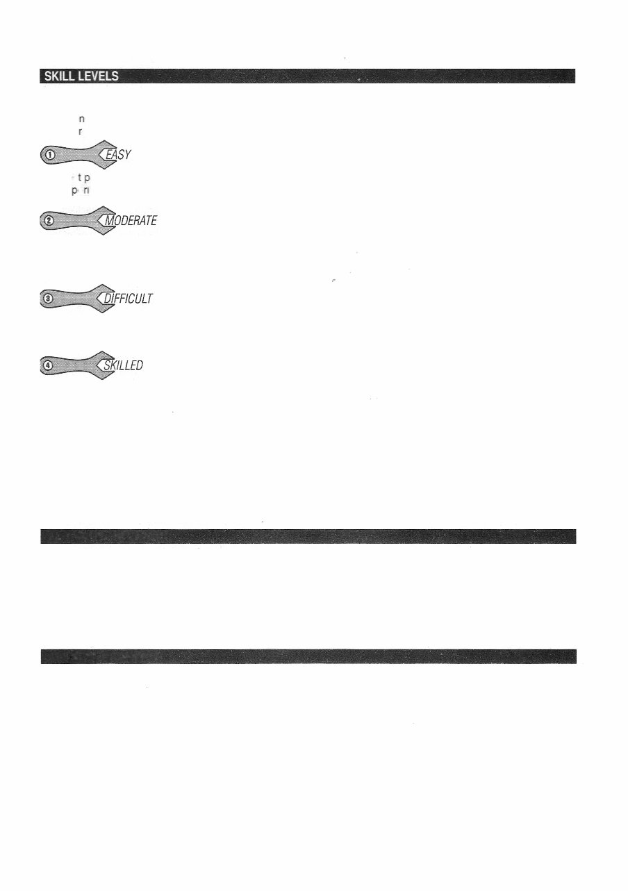
In order to provide all of- our users, paicularly the DIVers, with a feeling for the scope of a given procedure or
task before tackling it we have included a rating system denoting the suggested skill level needed when
performi g a paicular procedure. One of the following icons will be included at the beginning of most
procedu es:
EASY. These procedures are aimed primarily at the DIVer and can be classified, for
the mos a, as basic maintenance procedures; battery, fluids, filters, plugs, etc. Although certainly valuable to
any ex e ·ence level, they will generally be of little importance to a technician.
MODERAT E. These procedures are suited for a DIVer with experience and a
working knowledge of mechanical procedures. Even an advanced DIVer or professional technician will
occasionally refer to these procedures. They will generally consist of component repair and seice procedures,
adjustments and minor rebuilds.
-
DIFFICULT. These procedures are aimed at the advanced DIVer and professional
technician. They will deal with diagnostics, rebuilds and internal engine/drive components and will frequently
require special tools.
SKILLED. These procedures are aimed at highly skilled technicians and should not
be attempted without previous experience. They will usually consist of machine work, internal engine work and
gear case rebuilds.
Please remember one thing when considering the above ratings-they are a guide for judging the complexity
of a given procedure and are subjective in nature. Only you will know what your experience level is, and only
you will know when a procedure may be outside the realm of your capability. First time DIVer, or life-long marine
technician, we all approach repair and service differently so an easy procedure for one person may be a difficult
procedure for another, regardless of experience level. All skill level ratings are meant to be used as a guide only!
Use them to help make a judgement before undeaking a particular procedure, but by all means read through
the procedure first and make your own decision-after all, our mission at Seloc is to make boat maintenance
_and repair easier for everyone whether you are changing the oil or rebuilding an engine. Enjoy boating!
ALL RIGHTS RESERVD -
,
No pa of this publication may be reproduced, transmitted or stored in any form or by any means, electronic or
mechanical, including photocopy, recording, or by information storage or retrieval system, without prior written
permission from the publisher.
The materials contained in this manual are the intellectual property of Seloc Publishing, Inc., a Pennsylvania
corporation, and are protected under the laws of the United States of America at Title 17 of the United States
Code. Any effos to reproduce any of the content of this manual, in any form, without the express written
permission of Seloc Publishing, Inc. is punishable by a fine of up to $250,000 and 5 years in jail, plus the
recovery of all proceeds including attorneys fees.
ACKNOWLEDGMENTS
-
Seloc Publishing expresses appreciation to the following companies who suppoed the production of this
book:
• Marine Mechanics Institute-Orlando, FL
• Belks Marine-Holmes, PA
Thanks to John Haung and Judy Belk of Belk's Marine for for there assistance, guidance, patience and
access to some of the motors photographed for this manual.
Seloc Publishing would like to express thanks to the fine companies who participate in the production of all our
books:
• Hand tools supplied by Craftsman are used during all phases of our vehicle teardown and photography.
• Many of the fine specialty tools used in our procedures were provided courtesy of Lisle Corporation.
• Much of our shop's electronic testing equipment was supplied by Universal Enterprises Inc. (UEI).
You're Reading a Preview
What's Included?
Fast Download Speeds
Online & Offline Access
Access PDF Contents & Bookmarks
Full Search Facility
Print one or all pages of your manual
$39.99
$51.99
Viewed 13 Times Today


Secure transaction
What's Included?
Fast Download Speeds
Online & Offline Access
Access PDF Contents & Bookmarks
Full Search Facility
Print one or all pages of your manual
$39.99
$51.99
This manual is the complete factory service repair workshop manual for 2002-2006 Johnson Evinrude 40-250HP 2-Stroke Outboard engines. It offers professional repair, service, and troubleshooting procedures that have been trusted by mechanics and technicians for years.
- Complete Factory Service Repair Workshop Manual specifically for 2002-2006 Johnson Evinrude 40-250HP 2-Stroke Outboards
- Available for instant access on your computer, tablet, or smartphone
- Professional manual covering all repairs, servicing, and troubleshooting procedures for these outboard engines
- Contains detailed photos and diagrams to guide through every repair step
- Highly valued by professional mechanics and technicians
- Can be printed out in full or in part as needed
- Use on multiple computers ensuring flexibility in your repair work
- No limitations or trial periods – you receive the full manual
- No expiration or renewal fees
- Fully compatible with Windows and MAC computers
Thanks for looking at this item, please click on the Button.


