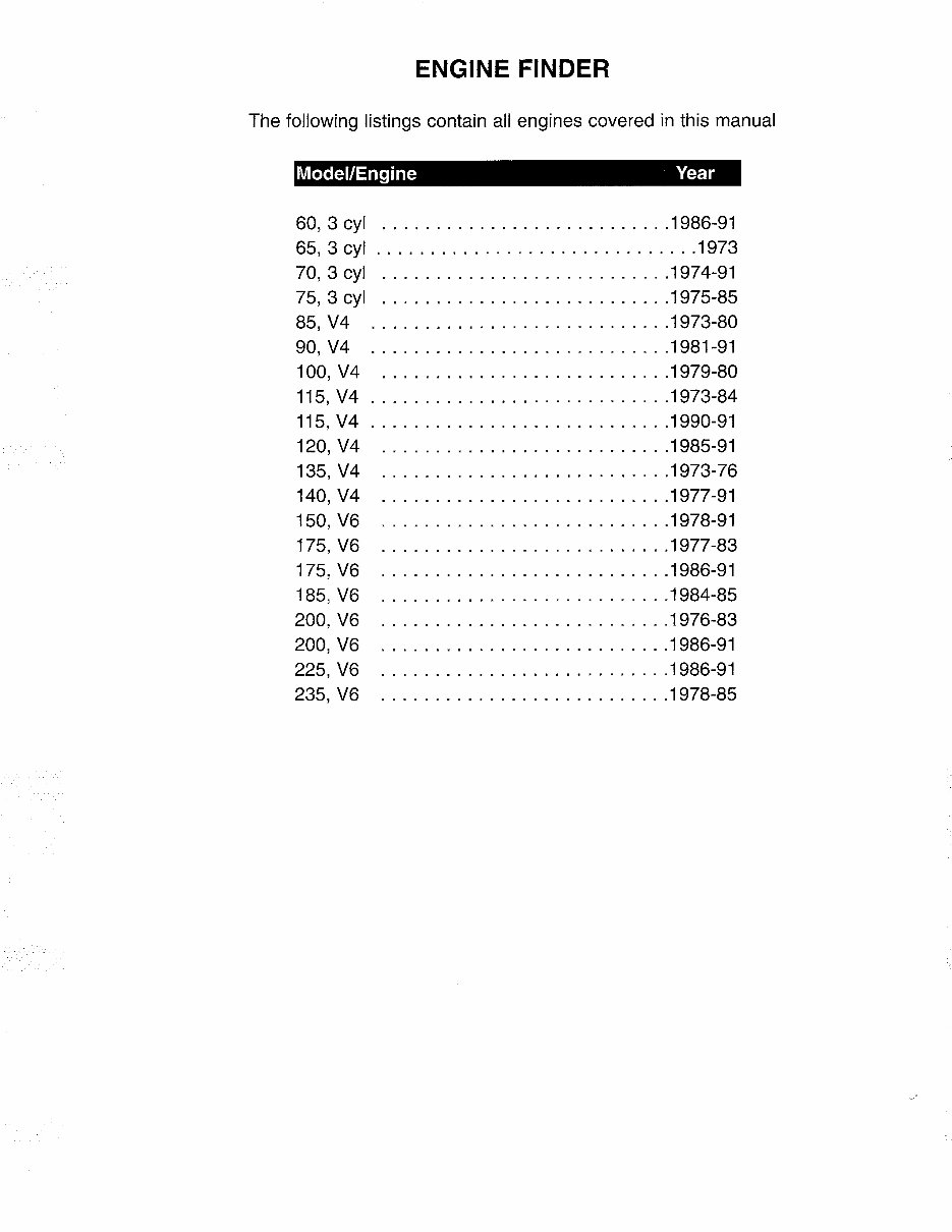
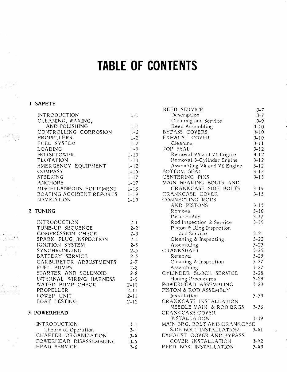
TABLE OF CONTENTS 1 SAFETY REED SERVICE 3-7 INTRODUCTION 1-1 Description 3-7 CLEANING, WAXING, Cleaning and Service 3-9 AND POLISHING 1-1 Reed Asseinbling 3-10 CONTROLLING CORROSION 1-2 BYPASS COVERS 3-10 PROPELLERS 1-2 EXHAUST COVER 3-10 FUEL SYSTEM 1-7 Cleaning 3-11 LOADING 1-9 TOP SEAL 3-12 HORSEPOWER 1-10 Removal V4- and V6 Engine 3-12 FLOTATION 1-10 Removal 3-Cylinder Engine 3-12 EMERGENCY EQUIPMENT 1-12 Assembling V4- and V6 Engine 3-12 COMPASS 1-15 BOTTOM SEAL 3-12 STEERING 1-17 CENTERING PINS 3-l3 ANCHORS 1-17 MAIN BEARING BOLTS AND MISCELLANEOUS EQUIPMENT 1-18 CRANKCASE SIDE BOLTS 3-14- BOATING ACCIDENT REPORTS 1-19 CRANKCASE COVER 3-15 NAVIGATION 1-19 CONNECTING RODS AND PISTONS 3-15 2 TUNING Removal 3-16 Disassembly 3-17 INTRODUCTION 2-1 Rod Inspection & Service 3-19 TUNE-UP SEQUENCE 2-2 Piston & Ring Inspection COMPRESSION CHECK 2-3 and Service 3-21 SPARK PLUG INSPECTION 2-4- Cleaning & Inspecting 3-22 IGNITION SYSTEM 2-5 Assembling 3-23 SYNCHRONIZING 2-5 CRANKSHAFT 3-25 BATTERY SERVICE 2-5 Removal 3-25 CARBURETOR ADJUSTMENTS 2-7 Cleaning & Inspection 3-27 FUEL PUMPS 2-8 Assembling 3-27 STARTER AND SOLENOID 2-8 CYLINDER BLOCK SERVICE 3-28 INTERNAL WIRING HARNESS 2-9 Honing Procedures 3-29 WATER PUMP CHECK 2-10 POWERHEAD ASSEMBLING 3-29 PROPELLER 2-11 PISTON & ROD ASSEMBL Y LOWER UNIT 2-11 Installa tion 3-33 BOAT TESTING 2-12 CRANKCASE INSTALLATION NEEDLE MAIN & ROD BRGS 3-36 3 POWERHEAD CRANKCASE COVER INST ALLA TION 3-39 INTRODUCTION 3-1 MAIN BRG. BOLT AND CRANKCASE Theory of Opera tion 3-1 SIDE BOLT INSTALLATION 3- 1 J1 CHAPTER ORGANIZATION 3-4- EXHAUST COVER AND BYPASS POWERHEAD DISASSEMBLING 3-5 COVER INSTALLATION 3-1J.2 HEAD SERVICE 3-6 REED BOX INSTALLATION 3-43
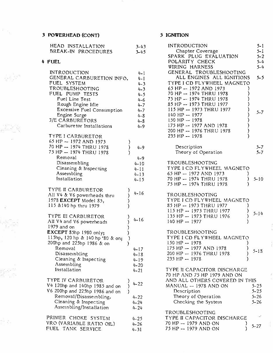
3 POWERHEAD (CONT) 5 IGNITION HEAD INST ALLA TION 3-43 INTRODUCTION 5-1 BREAK-IN PROCEDURES 3-45 Chapter Coverage 5-1 SPARK PLUG EVALUATION 5-2 4 FUEL POLARITY CHECK 5-4 WIRING HARNESS 5-4 INTRODUCTION 4-1 GENERAL TROUBLESHOOTING GENERAL CARBURETION INFO. 4-1 ALL ENGINES ALL IGNITIONS 5-5 FUEL SYSTEM 4-3 TYPE I CD FLYWHEEL MAGNETO TROUBLESHOOTING 4-3 65 HP -- 1972 AND 1973 ) FUEL PUMP TESTS 4-5 70 HP -- 1974 THRU 1978 ) Fuel Line Test 4-6 75 HP -- 1974 THRU 1978 ) Rough Engine Idle 4-7 85 HP -- 1973 THRU 1977 ) Excessive Fuel Consumption 4-7 115 HP -- 1973 THRU 1977 ) 5-7 Engine Surge 4-8 140 HP -- 1977 ) J/E CARBURETORS 4-8 150 HP -- 1978 ) Carburetor Installations 4-9 175 HP -- 1977 AND 1978 ) 200 HP -- 1976 THRU 1978 ) TYPE I CARBURETOR 235 HP -- 1978 ) 65 HP -- 1972 AND 1973 ) 70 HP -- 1974 THRU 1978 ) 4-9 Descr iption 5-7 75 HP -- 1974 THRU 1978 ) Theory of Operation 5-7 Removal 4-9 Disassembling 4-10 TROUBLESHOOTING Cleaning & Inspecting 4-11 TYPE I CD FL YWHEEL MAGNETO Assembling 4-13 65 HP -- 1972 AND 1973 ) Installa tion 4-15 70 HP -- 1974 THRU 1978 ) 5-10 75 HP -- 1974 THRU 1978 ) TYPE II CARBURETOR ) 4-16 All V4 & V6 powerheads thru ) TROUBLESHOOTING 1978 EXCEPT Model 85, ) TYPE I CD FL YWHEEL MAGNETO 115 &140 hp thru 1979 ) 85 HP -- 1973 THRU 1977 ) 115 HP -- 1973 THRU 1977 ) 5-14 TYPE III CARBURETOR ) 135 HP -- 1973 THRU 1976 ) All V4 and V6 powerheads ) 4-16 140 HP -- 1977 ) 1979 and on ) EXCEPT 85hp 1980 only; ) TROUBLESHOOTING 115hp, 120 hp & 140 hp '80 & on; ) TYPE I CD FL YWHEEL MAGNETO 200hp and 225hp 1986 & on ) 150 HP -- 1978 ) Removal 4-17 175 HP -- 1977 AND 1978 ) 5-13 Disassembling 4-18 200 HP -- 1976 THRU 1978 ) Cleaning & Inspecting 4-19 235 HP -- 1978 ) Assern bling 4-20 Installa tion 4-21 TYPE II CAPACITOR DISCHARGE 70 HP AND 75 HP 1979 AND ON TYPE IV CARBURETOR ) 4-22 AND ALL OTHERS COVERED IN THIS V4 120hp and 140hp 1985 and on ) MANUAL -- 1978 AND ON 5-25 V6 200hp and 225hp 1986 and on ) Descr iption 5-25 Removal/Disassem bUng. 4-22 Theory of Operation 5-26 Cleaning & Inspecting 4-24 Checking the System 5-26 Assern bling/Installa tion 4-24 TROUBLESHOOTING PRIMER CHOKE SYSTEM 4-25 TYPE II CAPACITOR DISCHARGE .. VRO (VARIABLE RATIO OIL) 4-26 70 HP -- 1979 AND ON ) 5-27 FUEL TANK SERVICE 4-31 75 HP -- 1979 AND ON )
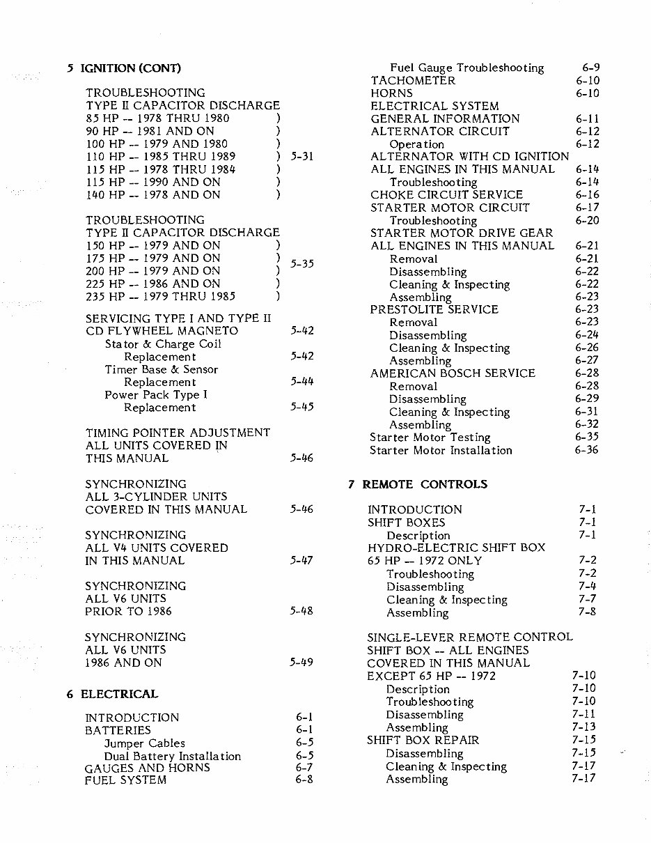
5 IGNITION (CONT) Fuel Gauge Troubleshooting 6-9 TACHOMETER 6-10 TROUBLESHOOTING HORNS 6-10 TYPE II CAPACITOR DISCHARGE ELECTRICAL SYSTEM 85 HP -- 1978 THRU 1980 ) GENERAL INFORMATION 6-11 90 HP -- 1981 AND ON ) ALTERNA TOR CIRCUIT 6-12 100 HP -- 1979 AND 1980 ) Operation 6-12 110 HP -- 1985 THRU 1989 ) 5-31 AL TERNA TOR WITH CD IGNITION 115 HP -- 1978 THRU 1984 ) ALL ENGINES IN THIS MANUAL 6-14 115 HP -- 1990 AND ON ) Troubleshooting 6-14 140 HP -- 1978 AND ON ) CHOKE CIRCUIT SERVICE 6-16 STARTER MOTOR CIRCUIT 6-17 TROUBLESHOOTING Troubleshooting 6-20 TYPE II CAPACITOR DISCHARGE ST AR TER MOTOR DRIVE GEAR 150 HP -- 1979 AND ON ) ALL ENGINES IN THIS MANUAL 6-21 175 HP -- 1979 AND ON ) 5-35 Removal 6-21 200 HP -- 1979 AND ON ) D isasse mb ling 6-22 225 HP -- 1986 AND ON ) Cleaning & Inspecting 6-22 235 HP -- 1979 THRU 1985 ) Assembling 6-23 PRESTOLITE SERVICE 6-23 SER VICING TYPE I AND TYPE II Removal 6-23 CD FLYWHEEL MAGNETO 5-42 Disassembling 6-24 Stator & Charge Coil Cleaning & Inspecting 6-26 Replacement 5-42 Assembling 6-27 Timer Base & Sensor AMERICAN BOSCH SERVICE 6-28 Replace men t 5-44 Removal 6-28 Power Pack Type I Disassembling 6-29 Replacement 5-45 Cleaning & Inspecting 6-31 Assembling 6-32 TIMING POINTER ADJUSTMENT Starter Motor Testing 6-35 ALL UNITS COVERED IN Starter Motor Installation 6-36 THIS MANUAL 5-46 S YNCHRO NIZING 7 REMOTE CONTROLS ALL 3-CYLINDER UNITS COVERED IN THIS MANUAL 5-46 INTRODUCTION 7-1 SHIFT BOXES 7-1 SYNCHRONIZING Description 7-1 ALL V4 UNITS COVERED HYDRO-ELECTRIC SHIFT BOX IN THIS MANUAL 5-47 65 HP -- 1972 ONLY 7-2 Troubleshooting 7-2 SYNCHRONIZING Disassembling 7-4 ALL V6 UNITS Cleaning & Inspecting 7-7 PRIOR TO 1986 5-48 Assembling 7-8 SYNCHRONIZING SINGLE-LEVER REMOTE CONTROL ALL V6 UNITS SHIFT BOX -- ALL ENGINES 1986 AND ON 5-49 COVERED IN THIS MANUAL EXCEPT 65 HP -- 1972 7-10 6 ELECTRICAL Description 7-10 Troubleshooting 7-10 INTRODUCTION 6-1 Disassembling 7-11 BATTERIES 6-1 Assembling 7-13 Jumper Cables 6-5 SHIFT BOX REP AIR 7-15 Dual Battery Installation 6-5 Disassembling 7-15 GAUGES AND HORNS 6-7 Cleaning & Inspecting 7-17 FUEL SYSTEM 6-8 Assembling 7-17
8 LOWER UNIT ALL UNITS 1978 AND ON Description 8-63 DESCRIPTION 8-1 Troubleshooting 8-63 CHAPTER COVERAGE 8-1 Removal 8-65 PROPELLER SERVICE 8-2 Removal 8-3 WATER PUMP REMOVAL 8-67 Installa tion 8-4 LOWER UNIT LUBRICATION 8-4 Lower Unit Disassembling 8-67 Draining 8-4 "Frozen" Propeller Shaft 8-70 Filling 8-5 Continued Disassembling 8-70 ELECTRIC SHIFT Cleaning & Inspecting 8-74 TWO SOLENOIDS Assembling 8-77 65 HP -- 1972 8-5 Description 8-5 WATER PUMP INSTALLA nON 8-85 Troubleshooting 8-6 Removal 8-8 Lower Unit Installation 8-88 Functional Check 8-88 "FROZEN" PROPELLER 8-89 WATER PUMP REMOVAL 8-9 Lower Unit Disassembling 8-10 9 POWER TILT/TRIM "Frozen" Propeller Shaft 8-12 Continued Disassembling 8-12 SYSTEM DESCRIPTION 9-1 Cleaning & Inspecting 8-16 COMPONENT FEATURES 9-2 Assembling 8-18 OPERATION 9-3 TROUBLESHOOTING WATER PUMP INSTALLATION 8-28 MECHANICAL COMPONENTS 9-6 Problems & Corrections 9-8 Lower Unit Installation 8-31 Troubleshooting with Equipment 9-10 Functional Check 8-32 TROUBLESHOOTING ELECTRICAL SYSTEM MECHANICAL SHIFT ALL 1978, 1979, 1980 HYDRAULIC ASSIST AND CIH 1981 ONLY 9-12 SHIFT DISCONNECT UNDER TROUBLESHOOTING LOWER CARBURETOR ELECTRICAL SYSTEM 65 HP TO 135 HP -- 1973 THRU 1975 MODELS 1981 AND ON 85 HP TO 200 HP -- 1976 AND 1977 EXCEPT CIH 9-14 Description 8-33 SYSTEM SERVICE 9-17 Troubleshooting 8-33 Removal 9-17 Removal 8-36 Disassembling 9-18 Cleaning & Inspecting 9-21 WATER PUMP REMOVAL 8-36 Assembling & Installation 9-21 Trim Motor Test & Repair 9-25 Lower Unit Disassembling 8-37 Mount Til t/Trim 1978-1980 9-28 "Frozen" Propeller Shaft 8-39 Mount Tilt/Trim 1981 & On 9-28 Continued Disassembling 8-39 UNIQUE TRIM/TILT Cleaning & Inspecting 8-48 SOME V4 UNITS PRIOR TO 1978 9-29 Assembling 8-48 10 MAINTENANCE WATER PUMP INSTALLATION 8-59 Lower Unit Installation 8-62 INTRODUCTION 10-1 Functional Check 8-63 ENGINE MODEL NUMBERS 10-2 FIBERGLASS HULLS 10-3 MECHANICAL SHIFT ALUMINUM HULLS 10-3 SHIFT DISCONNECT UNDER BELOW WATERLINE SERVICE 10-4. LOWER CARBURETOR SUBMERGED ENGINE SERVICE 10-5 70 HP -- 1976 AND 1977 WINTER STORAGE 10-7 75 HP -- 1975 THRU 1977 LOWER UNIT SERVICE 10-9
10 MAINTENANCE (CONT) HOSE ROUTING PRIMER CHOKE V4 ENGINES A-14 Draining 10-10 V6 ENGINES A-15 Fillirlg 10-11 BATTERY STORAGE 10-12 PRESEASON PREPARATION 10-13 WIRING IDENTIFICATION DRA WINGS 65 hp -- 3-cylinder wi th al terna tor -- 1972 A-16 11 OUTBOARD JET DRIVE 70 hp -- 1974-1975 wi thout safety swi tch INTRODUCTION 11-1 75 hp -- 1975 A-17 Description & Operation 11-1 70 hp and 75 hp -- 1976 & 77 A-18 General Information 11-1 70 hp and 75 hp -- 1978 A-19 Model Identification 60 hp 1985 & on A-20 Serial Numbers 11-1 70 hp 1979 & On A-20 REMOVAL & DISASSEMBLING 11-2 75 hp 1979-82 A-20 CLEANING & INSPECTING 11-6 85 hp, 115 hp, Bearing Assembly 11-6 and 135 hp -- 1972-1976 A-2l Drlveshaft & Associated Parts 11-6 Reverse Gate 11-6 85 hp & 115 hp -- 1977 A-22 Jet Impeller 11-7 140 hp -- 1977-84 A-22 Water Pump 11-7 85 hp - 1978-80 A-23 ASSEMBLING 11-9 90 hp 1981 & On A-23 Water Pump 11-10 100 hp 1979-80 A-23 Jet Drive Installation 11-12 110 hp -- 1985-89 A-23 ADJUSTMENTS 11-14 115 hp -- 1978-84 A-23 Cable Alignment 115 hp -- 1990 & On A-23 and Free "Play" 11-14 120 hp -- 1985 & On A-23 Neutral Stop 11-15 120 hp -- 1986 & On A-26 Trim Adjustment 11-16 140 hp -- 1985 Only A-23 L UB RI CA TI 0 N 11-17 140 hp -- 1986 & On A-26 OUTBOARD JET CHART 11-18 175 hp & 200 hp -- 1977-78 A-24 235 hp -- 1978 A-24 150 hp -- 1978-85 A-25 APPENDIX 150 hp -- 1986 & On A-27 175 hp -- 1979-85 A-25 METRIC CONVERSION CHART A-I 175 hp -- 1986 & On A-27 POWERHEAD SPECIFICA TIONS A-2 185 hp -- 1984-85 A-25 TORQUE SPECIFICATIONS A-3 200 hp -- 1979-85 A-25 ENGINE SPECIFICATIONS AND 200 hp -- 1986 & On A-27 TUNE-UP ADJUSTMENTS A-4 225 hp -- 1986 & On A-27 GEAR OIL CAPACITIES A-13 235 hp -- 1979-85 A-25
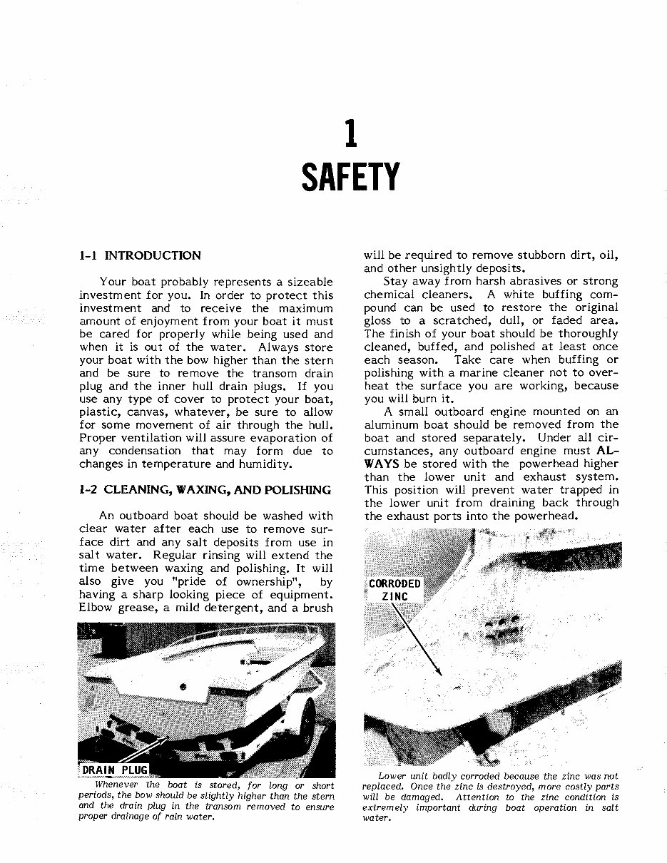
1 SAFETY 1-1 INTRODUCTION Your boat probably represents a sizeable investment for you. In order to protect this investment and to receive the maximum amount of enjoyment from your boat it must be cared for properly while being used and when it is ou t of the water. Al wa ys store your boat with the bow higher than the stern and be sure to remove the transom drain plug and the inner hull drain plugs. If you use any type of cover to protect your boat, plastic, canvas, whatever, be sure to allow for some movement of air through the hull. Proper ventilation will assure evaporation of any condensation that may form due to changes in temperature and humidity. 1-2 CLEANING, WAXING, AND POLISHING An outboard boat should be washed with clear water after each use to remove sur- face dirt and any salt deposits from use in salt water. Regular rinsing will extend the time between waxing and polishing. It will also give you "pride of ownership", by having a sharp looking piece of equipment. Elbow grease, a mild detergent, and a brush Whenever the boat is stored, for long or short periods, the bow should be slightly higher than the stern and the drain plug in the transom removed to ensure proper drainage of rain water. will be required to remove stubborn dirt, oil, and other unsightly deposits. Stay away from harsh abrasives or strong chemical cleaners. A white buffing com- pound can be used to restore the original gloss to a scratched, dull, or faded area. The finish of your boat should be thoroughly cleaned, buffed, and polished at least once each season. Take care when buffing or polishing with a marine cleaner not to over- heat the surface you are working, because you will burn it. A small outboard engine mounted on an aluminum boat should be removed from the boat and stored separately. Under all cir- cumstances, any outboard engine must AL- WAYS be stored with the powerhead higher than the lower unit and exhaust system. This position will prevent water trapped in the lower unit from draining back through the exhaust ports into the powerhead. Lower unit badly corroded because the zinc was not replaced. Once the zinc is destroyed, more costly parts will be damaged. Attention to the zinc condition is extremely important during boat operation in salt water.
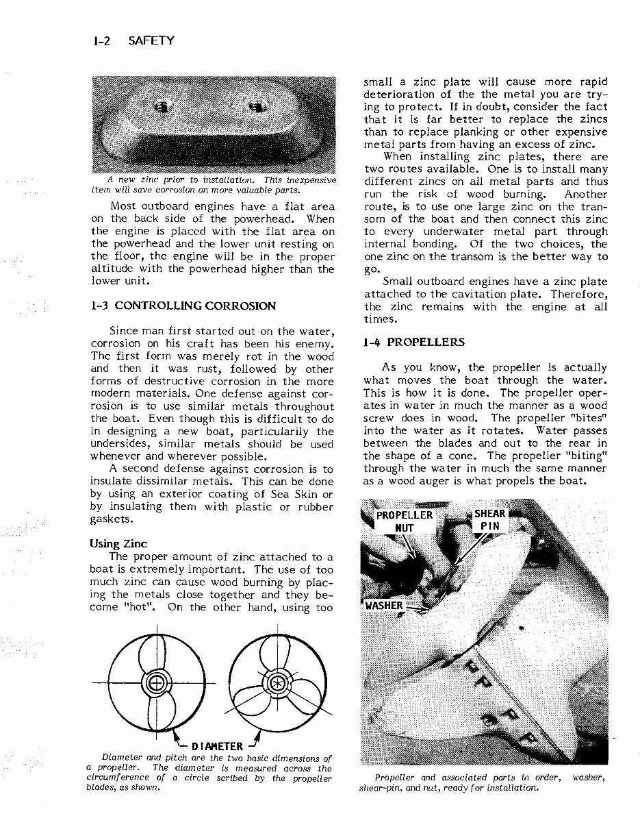
1-2 SAFETY A new zinc prior to installation. This inexpensive item will save corrosion on more valuable parts. Most outboard engines have a flat area on the back side of the power head. When the engine is placed with the flat area on the power head and the lower unit resting on the floor, the engine will be in the proper al titude with the power head higher than the lower unit. 1-3 CONTROLLING CORROSION Since man first started out on the water, corrosion on his craft has been his enemy. The first form was merely rot in the wood and then it was rust, followed by other forms of destructive corrosion in the more modern materials. One defense against cor- rosion is to use similar metals throughout the boat. Even though this is difficult to do in designing a new boat, particularily the undersides, similar metals should be used whenever and wherever possible. A second defense against corrosion is to insulate dissimilar metals. This can be done by using an exterior coating of Sea Skin or by insulating them with plastic or rubber gaskets. Using Zinc The proper amount of zinc attached to a boat is extremely important. The use of too much zinc can cause wood burning by plac- ing the metals close together and they be- come "hot". On the other hand, using too Diameter and pitch are the two basic dimensions of a propeller. The diameter is measured across the circumference of a circle scribed by the propeller blades, as shown. small a zinc plate will cause more rapid deteriora tion of the the metal you are try- ing to protect. If in doubt, consider the fact tha tit is far better to replace the zincs than to replace planking or other expensive metal parts from having an excess of zinc. When installing zinc plates, there are two routes available. One is to install many different zincs on all metal parts and thus run the risk of wood burning. Another route, is to use one large zinc on the tran- som of the boat and then connect this zinc to every underwater metal part through internal bonding. Of the two choices, the one zinc on the transom is the better way to go. Small outboard engines have a zinc plate attached to the cavitation plate. Therefore, the zinc remains with the engine at all times. 1-4 PROPELLERS As you know, the propeller is actually what moves the boat through the water. This is how it is done. The propeller oper- ates in water in much the manner as a wood screw does in wood. The propeller "bites" into the water as it rotates. Water passes between the blades and out to the rear in the shape of a cone. The propeller "biting" through the water in much the same manner as a wood auger is what propels the boat. Propeller and associated parts in order, washer, shear-pin, and nut, ready for installation.
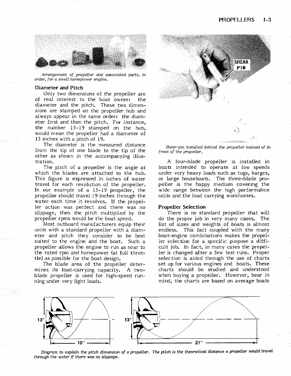
Arrangement of propeller and associated parts, in order, for a small horsepower engine. Diameter and Pitch Only two dimensions of the propeller are of real interest to the boat owner: the diameter and the pitch. These two dimen- sions are stamped on the propeller hub and always appear in the same order: the diam- eter first and then the pitch. For instance, the number 15-19 stamped on the hub, would mean the propeller had a diameter of 15 inches with a pitch of 19. The diameter is the measured distance from the tip of one blade to the tip of the other as shown in the accompanying illus- tration. The pitch of a propeller is the angle at which the blades are attached to the hub. This figure is expressed in inches of water travel for each revolution of the propeller. In our example of a 15-19 propeller, the propeller should travel 19 inches through the water each time it revolves. If the propel- ler action was perfect and there was no slippage, then the pitch multiplied by the propeller rpms would be the boat speed. Most outboard manufacturers equip their units with a standard propeller with a diam- eter and pitch they consider to be best sui ted to the engine and the boat. Such a propeller allows the engine to run as near to the rated rpm and horsepower (at full throt- tle) as possible for the boat design. The blade area of the propeller deter- mines its load-carrying capacity. A two- blade propeller is used for high-speed run- ning under very light loads. t----- 10" ---~ PROPELLERS 1-3 -',\., .....• . .. ~ . •... 0.J .. Shear-pin installed behind the propeller instead of in front of the propeller. A four-blade propeller is installed in boats intended to operate at low speeds under very heavy loads such as tugs, barges, or large houseboats. The three-blade pro- peller is the happy medium covering the wide range between the high performance uni ts and the load carrying workhorses. Propeller Selection There is no standard propeller that will do the proper job in very many cases. The list of sizes and weights of boats is almost endless. This fact coupled with the many boat-engine combinations makes the propel- ler selection for a specific purpose a diffi- cult job. In fact, in many cases the propel- ler is changed after a few test runs. Proper selection is aided through the use of charts set up for various engines and boats. These charts should be studied and understood w hen buying a propeller. However, bear in mind, the charts are based on average boats 21" Diagram to explain the pitch dimension of a propeller. The pitch is the theoretical distance a propeller would travel through the water if there was no slippage.
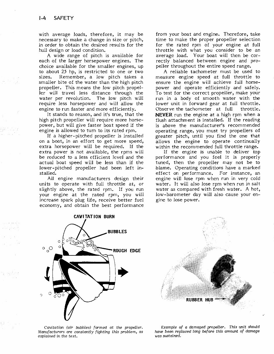
1-4 SAFETY with average loads, therefore, it may be necessary to make a change in size or pitch, in order to obtain the desired results for the hull design or load condition. A wide range of pitch is available for each of the larger horsepower engines. The choice available for the smaller engines, up to about 25 hp, is restricted to one or two sizes. Remember, a low pitch takes a smaller bite of the water than the high pitch propeller. This means the low pitch propel- ler will travel less distance through the water per revolution. The low pitch will require less horsepower and will allow the engine to run faster and more efficiently. It stands to reason, and it's true, that the high pitch propeller will require more horse- power, but will give faster boat speed if the engine is allowed to turn to its rated rpm. If a higher- pi tched propeller is installed on a boat, in an effort to get more speed, extra horsepower will be required. If the extra power is not available, the rpms will be reduced to a less efficient level and the actual boat speed will be less than if the lower-pitched propeller had been left in- stalled. All engine manufacturers design their units to operate with full throttle at, or slightly above, the rated rpm. If you run your engine at the rated rpm, you will increase spark plug life, receive better fuel economy, and obtain the best performance ') o 0 o CAVITATION BURN Cavitation (air bubbles) formed at the propeller. Manufacturers are constantly fighting this problem, as explained in the text. from your boat and engine. Therefore, take time to make the proper propeller selection for the rated rpm of your engine at full throttle with what you consider to be an average load. Your boat will then be cor- rectly balanced between engine and pro- peller throughout the entire speed range. A reliable tachometer must be used to measure engine speed at full throttle to ensure the engine will achieve full horse- power and operate efficiently and safely. To test for the correct propeller, make your run in a body of smooth water with the lower unit in forward gear at full throttle. Observe the tachometer at full throttle. NEVER run the engine at a high rpm when a flush attachment is installed. If the reading is above the manufacturer's recommended operating range, you must try propellers of greater pitch, until you find the one that allows the engine to operate continually within the recommended full throttle range. If the engine is unable to deliver top performance and you feel it is properly tuned, then the propeller may not be to blame. Operating conditions have a marked effect on performance. For instance, an engine will lose rpm when run in very cold water. It will also lose rpm when run in salt water as compared with fresh water. A hot, low-barometer day will also cause your en- gine to lose power. Example of a damaged propeller. This unit should have been replaced long before this amount of damage was sustained.
Upon purchasing this manual, you will receive a .PDF file containing an email contact. After contacting us, you will receive a reply with a link to access the manual for your 1979 Johnson Evinrude 150 HP Outboard.
This comprehensive manual covers every aspect of your machine, providing detailed guidance on every nut and bolt. With hundreds of pages, it offers instructions for tasks ranging from an oil change to a transmission swap, empowering both professional mechanics and DIY enthusiasts to tackle any issue. The manual includes numerous illustrations to assist you and features easy-to-understand text throughout.
Utilize the search function to navigate the manual efficiently and print the necessary pages as needed. This Factory Service Repair Manual serves as a thorough guide, walking you through the fundamentals of maintenance and repair in a step-by-step manner, imparting the knowledge that factory-trained technicians possess. By leveraging the insights within this service repair manual, any owner can confidently make informed decisions regarding the maintenance and repair of their machine.
Rest assured, in addition to providing a high-quality service manual, we are committed to delivering excellent customer service, ensuring your satisfaction with your purchase.
Recently Viewed
5,521,897Happy Clients
2,594,462eManuals
1,120,453Trusted Sellers
15Years in Business
Price:
Actual Price:
1979 Johnson Evinrude 150 HP Outboard Factory Service & Work Shop Manual