TABLE OF CONTENTS
1 SAFETY
INTRODUCTION
CLEANING, WAXING,
AND POLISHING
CONTROLLING CORROSION
PROPELLERS
FUEL SYSTEM
LOADING
HORSEPOWER
FLOTATION
EMERGENCY EQUIPMENT
COMPASS
STEERING
ANCHORS
MISCELLANEOUS EQUIPMENT
BOATING ACCIDENT REPORTS
NAVIGATION
2 N NING
INTRODUCTION
TUNE - UP SEQUENCE
COMPRESSION CHECK
SPARK PLUG INSPECTION
IGNITION SYSTEM
SYNCHRONIZING
BATTERY SERVICE
CARBURETOR ADJUSTMENTS
FUEL PUMPS
STARTER AND SOLENOID
INTERNAL WIRING HARNESS
WATER PUMP CHECK
PROPELLER
LOWER UNIT
BOAT TESTING
3 POWERHEAD
INTRODUCTION
Theory of Operation
CHAPTER ORGANIZATION
POWERHEAD DISASSEMBLING
HEAD SERVICE
REED SERVICE
Description
Cleaning and Service
Reed Assembling
Installation
EXHAUST COVER
Cleaning
TOP SEAL
Removal - - V4 Engine
Removal - - 3 - Cylinder Engine
BOTTOM SEAL
Inspec tion
CENTERING PINS
MAIN BEARING BOLTS AND
CRANKCASE SIDE BOLTS
CRANKCASE COVER
CONNECTING RODS
AND PISTONS
Removal
Disassembling
Rod Inspection and Service
Piston and Ring
Inspection and Service
Cleaning and Inspecting
Assembling
CRANKSHAFT
Removal
Cleaning and Inspecting
Assembling
CYLINDER BLOCK SERVICE
Honing Procedures
POWERHEAD A SS E M B L I N G
PISTON AND ROD ASSEMBLY
INSTALLATION
CRANKSHAFT INSTALLATION
NEEDLE MAIN AND
ROD BEARINGS
CRANKCASE COVER
BOTTOM SEAL INSTALLATION
TYPE ATTACHED TO LOWER
END OF CRANKCASE 3 - 43
© eblue-dist 2007
EXHAUST COVER AND
BYPASS COVER
INSTALLATION 3 - 44
REED BOX INSTALLATION 3 - 44
HEAP INSTALLATION 3 - 45
BREAK - IN PR.OCEDURES 3 - 46
4 FUEL
INTPODUCTICPN 4 - 1
GENERAL CARBIJR ETIPN
INFORMATION 4 - 1
FUEL SYSTEM 4 - 3
TROUBLESHOOTING 4 - 3
Fuel Pump Tests 4 - 5
Fuel Line Test 4 - 6
Rough Engine Idle 4 - 7
Excessive Fuel Consumption 4 - 7
Engine Surge 4 - 8
JOHNSCaW/EVINW UTPE
CAFBURETQPS 4-8
TYPE IA CARPURETOR
HBOWNCPRAFT, CaOUBLE BRL.
WITH HIGFJ- APJD LOW -
SPEED NEEDLE VALVES
50 HP -- 1958 AP'D IF39 1
60 HP -- 1964 ANC 1965 ) 4 - 9
75 HP -- 1960
1
TYPE IB CARBURETQR
SAME AS TYPE IA
EXCEPT WITH FIGF-SPEED
FIXED ORIFICE
60 WP - - 1366 ANP 1367 1
65 HP -- 196% 1
75 HP - - - 1961 TVRU 1965 1 4 - 9
80 IIP -- 1966 ANP 1967 1
85 MI? - - 196% 1
DESCRIPT1C)N
REMOVAL
CARBURETOR PISASSEMBLIP.'G 4 - 1 1
CLEANING AND IblSPECTIPJG 4 - 14
ASSEMBLING 4 - 17
TYPE I1 CARBURETOR
30 HP - - 1964 AND 1965
) 4 - 22
100 I-?P -- 1966 TMRU 1968 1
DESCRIPTION
Choke System
REEK OVAL
DISASSEMBLING
CEOKE SYSTEF"SEFV1CE 4-3$
Peat/Electric Choke
I? ernoval 4 - 35
Installation 4 - 37
All Electric Choke
F emovall & Pisassembling It-?.?
Assembling
Water Choke
Pescriptim
P ernoval
Installation
ASSEhWPWG
IVYFALLATION
Fl EL PUVP SERVICE
Trsubleshaot ing
Removal an8 Repair
Cleaninp and Inspecting
Assernbline, and Installation
FUEL TAWK SERVICE
© eblue-dist 2007
5 IGNITION
INTRODUCTION 5 - 1
Ignition Systems 5 - 2
SPARK PLUG EVALUATION 5 - 3
Removal 5 - 3
EXAMINATI@N 5-3
OTHER IGNITION PARTS 5 - 5
Description 5-5
TYPE I IGNITION
DISTRIRlJTOF VAGNETO
50 HP - - 1958 AND 1959
60 HP -- 1964 TVRIJ 1?66 )
75 HP -- 196Q TI4RtI 1965 )
80 HP -- 1966 1
Description
TRCPUALESHOOTI1\?G
SERVICING
General Information
Removal
Servicing
Cleaning: and Inspecting
Installation
BELT REPLACEMENT
Engine M istimed
TYPE I1 IGNITIQN
DISTRIBUTOR BATTEP Y
75 HI? -- 1961 THRU 1965
)
80 HP -- 1966 AND 1967
90 HP - - 1964 AND 1965 1
108 HP -- 1966
Description
TROUBLESHOOTING
SERVICING
Removal -
Cleaning and Inspecting
Installation
BELT REPLACEMENT
Engine Mistimed
Installation
TYPE I11 IGNITION
CAPACITOR lXSCHARGE (CLd)
WITM SENSOR
100 MP - - 1967, 1968,
AND 1972 )
115 HP -- 1969 AND 1970
125 HP - - 1971 AND 1972 )
TROUBLESHOQTING
100 HP -- 1967 AND 1968
TROUBLESHOOTING
115 HP -- 1969 AND 1370
TROLJBLESHQOTHNG
108 HP -- 1972
125 HP -- 1971 AN@ 1972
COVPONENT REPLACEMENT
Rotor Replacement
100 hp - - 1967
Sensor Replacement
100 hp -- 1967
Powerpack Replacement
100 hp -- 1967
COMPONENT REPLACEArENT
IGNITION PARTS UNPEF
FLY WHEEL: STATOR,
CISTRIBUTOR CAP,
EIST WIBUTOR ROTCW,
SENSOR ROTOR, APE? SEE1%
100 MP - - 8968 ANC 1972
115 HP -- 8969 ANP 1970
125 HP -- 1971 ANE 1972
W emoval
Cleaning and Inspecting
Assembling
CAPACITOR DISCWAR GE (CG)
WITM BREAKER P(3IbT5
55 HP 3 - CYL. -- 1968
AND 1969
60 HP 3-CYL. -- 1 978
AND 1971
6 5 MP V4 -- 19653
$5 EP V4 -- 1968 TEIRU 1972
100 MP V4 -- 197 1
Cescription
Safety
General Troubleshootiwe
All CD Wodels
Troubles hooting
55 hp - - 1968 and 1969
65 hp - - 1968
85 hp -- 1968
Troubles hooting
85 h~ - - 1969 thru 6972
100 hp -- 1971
Troubles hooting
40 hp - - 1970 and 197 1
CL IGNITION SYSTEV
PARTS REPLACEWENT
AND AEJUSTMENT
55 HP 3 - CYL - - 1968 eC 1969
60 HP 3-CYL -- 1570 & 1571
65 HP V4 -- 1968
85 flP V4 -- 1968 THRU 1972
100 HP V4 -- 1971
Removal
Cleaning and Inspecting
© eblue-dist 2007
5 IGNITION (CONT)
SYWCFRCNIZING
C"ISTRIBUT0R ANC CARBURETOR
hvP,Gh'FTQ IGNITION MGPELS
50 tiP 1958 ANL" 1959 5 - 92
SYNCH-'RCNIZING
CISTRIBUTOR AND CARBURETOR
BATTERY IGNITION
NAGNETQ IGNITION
60 HP - - 1964 THRU 1966
75 PI? -- 1960 THRU 6963
$0 HI' - - 1906 ANI3 1967
90 IF? -- 3964 ANE 1965
100 E? - - 1966 ANC 1967
6 ELECTRICAL
INTROIPUCTICPJ 6 - 1
BATTEPIES 6 - 1
Jumper Cables 6-5
Pual Battery Installatic\n 6 - 5
GAUGES AND FORPS 6 - 7
FUEL SYSTEbb
Fuel Gauge 6 - 8
Fuel Gauge Poskup 6-8
Fuel Gauge Troubleshooting 6 - 9
TACFOPJETER 6 - 10
KOWNS 6 - 10
ELECTRICAL SYSTEM
GENERAL IPIF(?Ri?4ATI@N 6-1 1
GENER ATCF CPARGIFG CIRCIJIT
Troubleshooting 6 - 12
Generator Service 6 - 10
Cleaning and Inspecting 6 - 18
Assemhli ng 6 - 20
ALTER NATPR CpAP GIPG CIRCUIT
Pperation 6 - 22
Troubleshooting 6 - 24
ALTERblATOFs WIW
PATTER Y IGb'.'ITI[ON
WC9PEkS 190 1 THR tJ 1967 6 - 25
ALTER PIPTOP VJITF" CP IGWITION
100 FP -- 1907 AND
ALL cp IGPIITIC\P. 1968
TPFelir 1972 6 - 27
Troubleshootinp 6 - 27
CYPKE CIRCUIT SERVICE 6 - 31
STAP TEP FVTCP CIPCIJIT SEPVICE
Circuit Pescription 6 - 31
Starter P'otor Description 6 - 32
Tr~ubleshsstin 6 - 34
Testim 6 - 34
STAP T E PCTCP, rmvE G E A R
Starter Removal
All \'hts 1958 Thru 1958 6 - 37
Starter Crive Removal 6 - 37
Cleanine and Inspecting 6 - 38
Installation 6 - 38
STARTEFF PRIVE GEAR SEW VICE
55 HE ' 3-CYLIIWPEP
1968 AFT 1965 1
60 WP 3-CXLIP.!@ER
1970 AND lQ71 1
85 HP W4 -- lQ49 TFRU 1972 ) 6 - 39
115 HP V4 -- 1969 ANT31 1870 )
125 VP Yk - - 1971 AND 1972 )
R ernoval 6 - 39
Pisassemblinp 6 - 40
Cleaning and Inspecting 6 - 41
Assembling 6 - 41
© eblue-dist 2007
PELCO-W EF4Y SERVICE
R ernoval 64 1
Disassembling 6-k2
Armature Testing 6 - 43
Cleaning and Inspecting 6 - 44
Assembling 6 - 45
AUTOLITE SERVICE
Removal 6 - 47
Disassembling 6 - 48
Armature Testing 6-48
Cleaning and Inspecting 6 - 50
PR ESTOLITE SER VICE
Removal from Starboard
Installation with
Separate Drive Gear 6 - 52
Removal from Port Side
Installation with
Drive Gear on
Armature Shaft 6 - 52
Disassembling 6 - 53
Armature Testing 6 - 53
Cleaning and Inspecting 6 - 55
Assembling 6 - 56
STARTER MOTOR TESTIP'G 6 - 57
STARTER MOTOR INSTALLATION 6 - 57
7 ACCESSORIES
DESCRIPTION 7 - 1
SHIFT BOXES 7 - 1
OLD - STYLE DOUBLE LEVER
Troubleshooting 7 - 3
h)isassembling 7 - 4
Cleaning and Inspecting 7 - 5
Assembling 7 - 5
NEW - STYLE SWIFT LEI'EF.
Troubleshooting 7 - 6
Removal 7 - 8
Disassembling 7 - 8
Cleaning and Inspecting 7-0
Assembling 7 - 10
ELECTRIC GEAR BOXES
AbJD SINGLE LEVER CONTROL
JOHNSON I JNITS 7 - 12
Troubleshooting 7 - 12
Disassembling 7 - 15
Cleaning and Inspecting 7 - 16
Assembling 7 - 17
PUSHBUTTON SHIFT BOX
EVINRUDE UNITS Ob'LY 7 - 1 "
Troubleshooting 7 - 20
Disassembling 7 - 22
Cleaning and Inspecting 7 - 24
Assembling 7-74
Troubleshooting 7-26
Disassembling 7 - 29
clean in^ and inspect in^ 7 - 31
Assembling 7 - 32
CABLE ENP FITTIPIG
IPJSTALEPTION AT
EWGIF'E EFT" 7 - 34
8 LOWER UNIT
DESCRIPTICN 8 - 11
CPAPTER COVERAGE 8 - 1
ILLUSTRATIONS 8 - 2
PROPELLER SERVICE 8 - 2
Propeller with Shear Pin
Removal 8 - 2
Installation 8 - 3
Exhaust Propeller 8 - 3
Removal 8-4
Installation 8 - 4
WATER PUMP REMOVAL 8-1 8
Lower Unit Pisassemblinp 8 - 1 E
Cleaning and Inspectinn $-
Lower Unit Assembling: 8 - 16
WATER PUMP INSTALLATIQN 8 - 19
Lower Unit %nstallatio 8 - 20
© eblue-dist 2007
8 LOWER UNIT (CONTI
TYPE H I L@lVJE hThTIT SEPVICE
VAPJUAL SFWT
SIPfGEE ENCLOSEI" RQLJSIIPJG
48 PP - - 1964 TERU BQR7 1
65 I-'P -- 1068
75 PF -- 1968 TFRU 1965 ) 8 - 22
80 PP -- 1066 ANP 1967 'B
85 EP - - l"68 )
WATER PUMP REMOVAL 8 - 24
Lower 1Jnit Pisassembliw p-sk
clean in^ and Inspecting 8-3"
kewer (Init Assemhline 8 - 31
WATER PUMP INSTALLATION P-36
Lower [!nit Installatio P- ?P
Pescription
Type I11 and Type IV Units 8 - 40
Troubles hooting
Type I11 and Type IV Units 8 - 48
Removal
Type III Units 8 - 43
WATER PUMP REMOVAL 8-Sg
Pisassembling 8-44
Cleaninp an8 Inspectinp $-50
Assembling 8 - 52
WATER PUMP INSTALLATION 8 - 60
Lower llnit lInstallaticm 8 - 6 1
TYPE 1IV LCYUER UP1.'IT
EkECTROKATIlr
BOO FB -- 1906 TPR P_I 11968 8 - 62
Troubleshooti~ 8 - 63
WATER PUMP REMOVAL 8 - 64
Lower Unit Pisassembling 8-h@
CBeanin and Inspecting 8-Go
Lower ifnit Asse~blinp 8 - 7 1
WATER PUMP INSTALLATICN 8 - 80
Lower Unit Installation 8-8 1
Description
Troubleshooting
Lower Unit Removal
WATER PUMP REMOVAL 8 - 86
Lower Unit Pisassembling 8 - 87
"Frozen'Tropeller Shaft 8 - 83
Cleaning and Inspecting 8 - 93
Lower Unit Assembling 8 - 95
WATER PUMP INSTALLATION 8- 105
Lower Unit Ynstallation 8-108
'FFFOZEf."T!?OPEkkER
Description 8-1 18
P emaval 8 - 1 10
9 HAND STARTER
10 MAINTENANCE
© eblue-dist 2007
APPENDIX
A-4
A - 8
A- 10
A-IC
A-P B
75 hp V4 with Papnets,
Generator, and
Standard Shift -- 1 O6 1
75 hp thru 90 hp V4
with Electric Shift
1961 thru 1965
80 hrz V4
with Generator -- 1966
88 hp V4 -- 1367
80 hp V4
with Electric Shift -- 1?67
85 hp V4 -- 15568
85 hp V4
with Electric Shift -- 1?68
$5 hp V4 with PJternator
%?69 and 1970
85 hp Y4 with Alternator -- 1972
$5 hp and 100 hp Vk
with Alternator -- 1.971
100 hp V4 with CD Ignition
I967 and 1968
100 hp V4 and 125 hp V4
with Alternator -- 1972
1 15 hp V4 -- 1969 and 1970
125 hp Y4 -- 1971
© eblue-dist 2007
SAFETY
1 - 1 INTRODUCTION
Your boat probably represents a sizeable
investment for you. In order to protect this
investment and to receive the maximum
amount of enjoyment from your boat it must
be cared for properly while being used and
when it is out of the water. Always store
your boat with the bow higher than the stern
and be sure to remove the transom drain
plug and the inner hull drain plugs. If you
use any type of cover to protect your boat,
plastic, canvas, whatever, be sure to allow
for some movement of air through the hull.
Proper ventilation will assure evaporation of
any condensation that may form due to
changes in temperature and humidity.
1 - 2 CLEANING, WAXING, AND POLISHING
An outboard boat should be washed with
clear water after each use to remove sur -
face dirt and any salt deposits from use in
salt water. Regular rinsing will extend the
time between waxing and polishing. It will
also give you " pride of ownership " , by
having a sharp looking piece of equipment.
Elbow grease, a mild detergent, and a brush
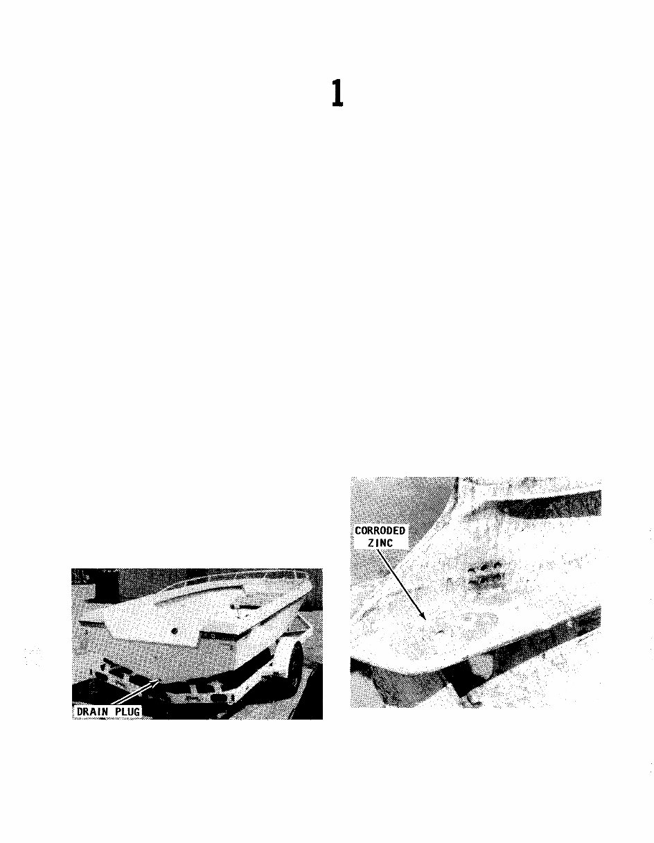
Whenever the boat is stored, for long or short
periods, the bow should be slightly higher than the stern
and the drain plug in the transom removed to ensure
proper drainage of rain water.
will be required to remove stubborn dirt, oil,
and other unsightly deposits.
Stay away from harsh abrasives or strong
chemical cleaners. A white buffing com -
pound can be used to restore the original
gloss to a scratched, dull, or faded area.
The finish of your boat should be thoroughly
cleaned, buffed, and polished at least once
each season. Take care when buffing or
polishing with a marine cleaner not to over -
heat the surface you are working, because
you will burn it.
A small outboard engine mounted on an
aluminum boat should be removed from the
boat and stored separately. Under all cir -
cumstances, any outboard engine must AL -
WAYS be stored with the powerhead higher
than the lower unit and exhaust system.
This position will prevent water trapped in
the lower unit from draining back through
the exhaust ports into the powerhead.
Lower unit badly corroded because the zinc was not
replaced. Once the zinc is destroyed, more costly parts
will be damaged. Attention to the zinc condition is
extremely important during boat operation in salt
water.
© eblue-dist 2007
I--2 SAFETY
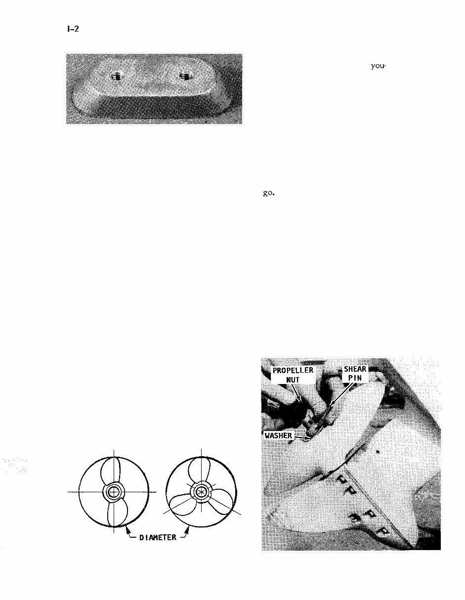
A new zinc prior to installation. This inexpensive
item will save corrosion on more valuable parts.
Most outboard engines have a flat area
on the back side of the powerhead. When
the engine is placed with the flat area on
the powerhead and the lower unit resting on
the floor, the engine will be in the proper
altitude with the powerhead higher than the
lower unit.
1 - 3 CONTROLLING CORROSION
Since man first started out on the water,
corrosion on his craft has been his enemy.
The first form was merely rot in the wood
and then it was rust, followed by other
forms of destructive corrosion in the more
modern materials. One defense against cor -
rosion is to use similar metals throughout
the boat. Even though this is difficult to do
in designing a new boat, particularily the
undersides, similar metals should be used
whenever and wherever possible.
A second defense against corrosion is to
insulate dissimilar metals. This can be done
by using an exterior coating of Sea Skin or
by insulating them with plastic or rubber
gaskets.
Using Zinc
The proper amount of zinc attached to a
boat is extremely important. The use of too
much zinc can cause wood burning by plac -
ing the metals close together and they be -
come " hot " . On the other hand, using too
Diameter and pitch are the two basic dimensions of
a propeller. The diameter is measured across the
circumference of a circle scribed by the propeller
blades, as shown.
small a zinc plate will cause more rapid
deterioration of the metal you. are trying to
protect. If in doubt, consider the fact that
is is far better to replace the zincs than to
replace planking or other expensive metal
parts from having an excess of zinc.
When installing zinc plates, there are
two routes available. One is to install many
different zincs on all metal parts and thus
run the risk of wood burning. Another
route, is to use one large zinc on the tran -
som of the boat and then connect this zinc
to every underwater metal part through
internal bonding. Of the two choices, the
one zinc on the transom is the better way to
go-
Small outboard engines have a zinc plate
attached to the cavitation plate. Therefore,
the zinc remains with the engine at all
times.
1 - 4 PROPELLERS
As you know, the propeller is actually
what moves the boat through the water.
This is how it is done. The propeller oper -
ates in water in much the manner as a wood
screw does in wood. The propeller " bites "
into the water as it rotates. Water passes
between the blades and out to the rear in
the shape of a cone. The propeller " biting "
through the water in much the same manner
as a wood auger is what propels the boat.
Propeller and associated parts in order, washer,
snear - pin, and nut, ready for installation.
© eblue-dist 2007
PROPELLERS 1 - 3
Arrangement of propeller and associated parts, in
order, for a small horsepower engine.
Diameter and Pitch
Only two dimensions of the propeller are
of real interest to the boat owner: the
diameter and the pitch. These two dimen -
sions are stamped on the propeller hub and
always appear in the same order: the diam -
eter first and then the pitch. For instance,
the number 15 - 19 stamped on the hub,
would mean the propeller had a diameter of
15 inches with a pitch of 19.
The diameter is the measured distance
from the tip of one blade to the tip of the
other as shown in the accompanying illus -
tration.
The pitch of a propeller is the angle at
which the blades are attached to the hub.
This figure is expressed in inches of water
travel for each revolution of the propeller.
In our example of a 15 - 19 propeller, the
propeller should travel 19 inches through the
water each time it revolves. If the propel -
ler action was perfect and there was no
slippage, then the pitch multiplied by the
propeller rpms would be the boat speed.
Most outboard manufacturers equip their
units with a standard propeller with a diam -
eter and pitch they consider to be best
suited to the engine and the boat. Such a
propeller allows the engine to run as near to
the rated rpm and horsepower (at full throt -
tle) as possible for the boat design.
The blade area of the propeller deter -
mines its load - carrying capacity. A two-
blade propeller is used for high - speed run -
ning under very light loads.
Shear - pin installed behind the propeller instead of in
front of the propeller.
A four - blade propeller is installed in
boats intended to operate at low speeds
under very heavy loads such as tugs, barges,
or large houseboats. The three - blade pro -
peller is the happy medium covering the
wide range between the high performdnce
units and the load carrying work horses.
Propeller Selection
There is no standard propeller that will
do the proper job in very many cases. The
list of sizes and weights of boats is almost
endless. This fact coupled with the many
boat - engine combinations makes the propel -
ler selection for a specific purpose a diffi -
cult job. In fact, in many cases the propel -
ler is changed after a few test runs. Proper
selection is aided through the use of charts
set up for various engines and boats. These
charts should be studied and understood
when buying a propeller. However, bear in
mind, the charts are based on average boats
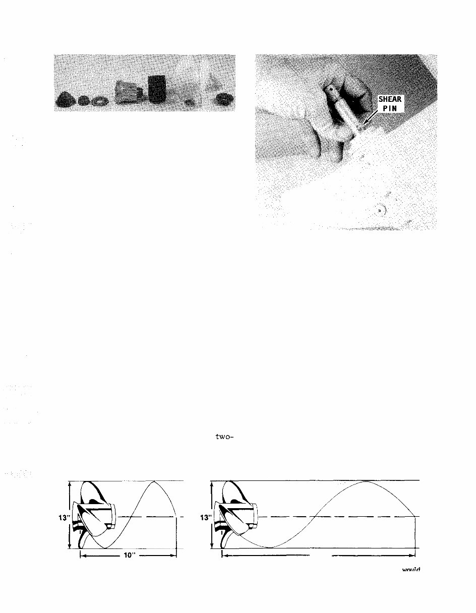
Diagram to explain the pitch dimension
through the water if there was no slippage.
1- 21 " -1
of a propeller. The pitch is the theoretical distance a propeller would
travel
© eblue-dist 2007
You're Reading a Preview
What's Included?
Lifetime Access
Access PDF Contents & Bookmarks
Print one or all pages of your manual

")