1993 Johnson Evinrude 100 HP 4 Cyl Outboard Factory Service & Work Shop Manual
What's Included?
Lifetime Access
Fast Download Speeds
Online & Offline Access
Access PDF Contents & Bookmarks
Full Search Facility
Print one or all pages of your manual
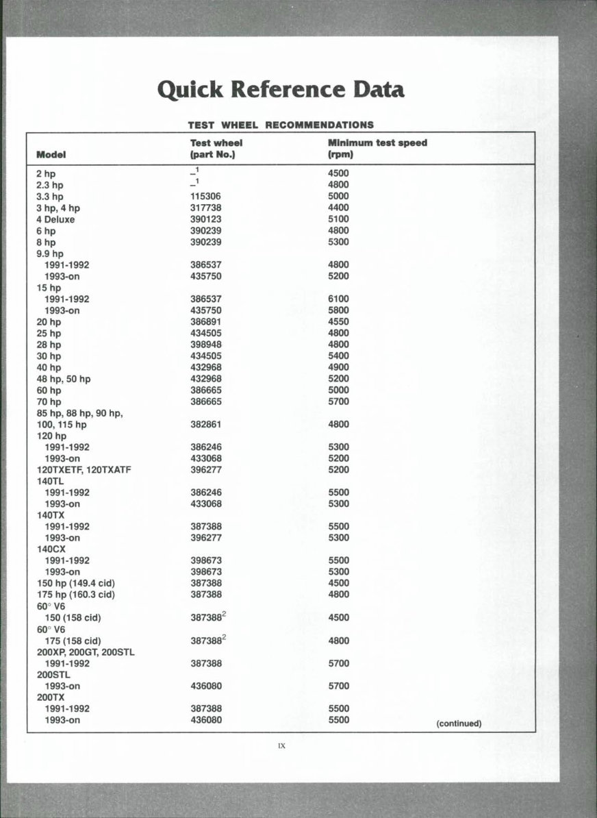
Quick Reference Data Model 2hp 2.3 hp 3.3 hp 3 hp, 4 hp 4 Deluxe 6hp 8hp 9.9 hp 1991-1992 1993-on 15 hp 1991-1992 1993-on 20 hp 25 hp 28 hp 30 hp 40 hp 48 hp, 50 hp 60 hp 70 hp 85 hp, 88 hp, 90 hp, 100,115 hp 120 hp 1991-1992 1993-on 120TXETF, 120TXATF 140TL 1991-1992 1993-on 140TX 1991-1992 1993-on 140CX 1991-1992 1993-on 150 hp (149.4 ctd) 175 hp (160.3 cid) 60° V6 150 (158 cid) 60° V6 175 (158 cid) 200XP, 200GT, 200STL 1991-1992 200STL 1993-on 200TX 1991-1992 1993-on TEST WHEEL Test wheel (part No.) _i _1 115306 317738 390123 390239 390239 386537 435750 386537 435750 386891 434505 398948 434505 432968 432968 386665 386665 382861 386246 433068 396277 386246 433068 387388 396277 398673 398673 387388 387388 387388^ 387388^ 387388 436080 387388 436080 RECOMMENDATIONS Minimum test speed (rpm) 4500 4800 5000 4400 5100 4800 5300 4800 5200 6100 5800 4550 4800 4800 5400 4900 5200 5000 5700 4800 5300 5200 5200 5500 5300 5500 5300 5500 5300 4500 4800 4500 4800 5700 5700 5500 ^50^ (continued) IX
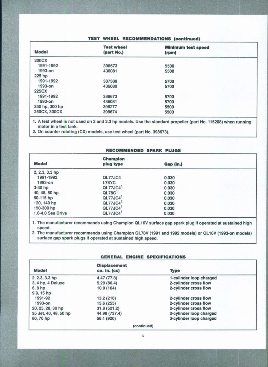
TEST WHEEL RECOMMENDATIONS (continued) Model 200CX 1991-1992 1993-on 225 hp 1991-1992 1993-on 225CX 1991-1992 1993-on 250 hp, 300 hp 250CX, 300CX 1. A test wheef is not used motor in a test tank. 2. On counter rotating (CX) Test wheel (part No.) 398673 436081 387388 436080 388673 436081 396277 398674 on 2 and 2.3 hp modeis. modeis, use test wheei Minimum test speed (rpm) 5500 5500 5700 5700 5700 5700 5500 5500 Use the standard propeMer (part No. 115208) when running (part No. 398673). RECOMMENDED SPARK PLUGS Model 2, 2.3, 3.3 hp 1991-1992 1993-on 3-30 hp 40, 48, 50 hp 60-115 hp 120,140 hp 150-300 hp 1.6-4.0 Sea Drive 1. The manufacturer recommends speed. 2. The manufacturer recommends Champion plug type QL77JC4 L78YC QL77JC4^ QL78C^ QL77JC4^ QL77JC4^ QL77JC4^ QL77JC4^ using Champion using Champion surface gap spark piugs if operated at sustained Gap (In.) 0.030 0.030 0.030 C.030 0.030 0.030 0.030 0.030 QL16V surface gap spark piug if operated at sustained high QL78V (1991 and 1992 models) or QL16V (1993-on modeis) high speed. GENERAL ENGINE SPECIFICATIONS Model 2,2.3,3.3 hp 3,4 hp, 4 Deiuxe 6,8hp 9.9,15hp 1991-92 1993-on 20,25,28,30 hp 35 Jet, 40,48,50 hp 60,70 hp Displacement cu. In. (cc) 4.47 (77.8) 5.29 (86.4) 10.0(164) 13.2(216) 15.6(255) 31.8(521.2) 44.99 (737.4) 56.1 (920) (continued) Type 1-cylinder ioop charged 2-cyiinder cross flow 2-cyiinder cross fiow 2-cyiinder cross fiow 2-cylinder cross fiow 2-cyiinder cross flow 2-cyiinder ioop charged 3-cylinder loop charged
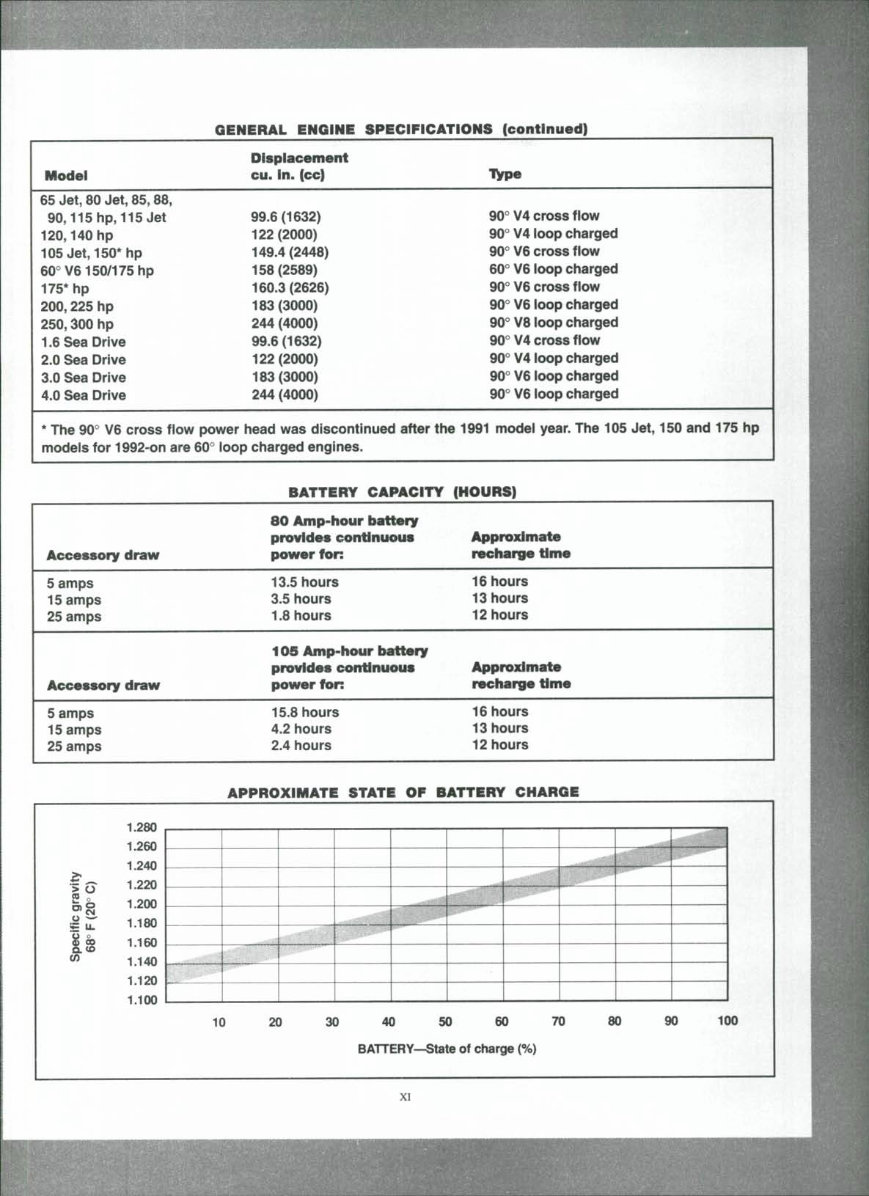
GENERAL ENGINE SPECIFICATIONS (continued) Model 65 Jet, 80 Jet, 85,88, 90,115 hp, 115 Jet 120,140 hp 105 Jet, 150* hp 60° V6150/175 hp 175* hp 200,225 hp 250, dOO hp 1.6 Sea Drive 2.0 Sea Drive 3.0 Sea Drive 4.0 Sea Drive Displacement cu. In. (cc) 99.6(1632) 122(2000) 149.4(2448) 158(2589) 160.3(2626) 183(3000) 244 (4000) 99.6(1632) 122(2000) 183(3000) 244 (4000) * The 90'' V6 cross flow power head was discontinued modeis for 1992-on are 60'' ioop charged engines. Type 90"" V4 cross flow 90° V4 loop charged 90° V6 cross fiow 60"" V6 ioop charged 90° V6 cross flow 90° V6 ioop charged 90° V8 ioop charged 90° V4 cross fiow 90° V4 ioop charged 90° V6 loop charged 90° V6 loop charged after the 1991 model year. The 105 Jet, 150 and 175 hp Accessory draw 5 amps 15 amps 25 amps Accessory draw 5 amps 15 amps 25 amps BATTERY CAPACITY SO Amp"hour battmry provides continuous power foR 13.5 hours 3.5 hours 1.8 hours 109 Amp-hour battery provides continuous power foR 15.8 hours 4.2 hours 2.4 hours (HOURS) Approximate recharge time 16 hours 13 hours 12 hours Approximate recharge time 16 hours 13 hours 12 hours APPROXIMATE STATE OF BATTERY CHARGE gravity 20° C) Specific 68° F( 1.280 1.260 1.240 1.220 1.200 1.160 1.140 1.120 1.100 10 2 0 3 0 4 0 5 0 6 0 7 0 8 0 9 0 100 BATTERY'-State of charge (%) XI
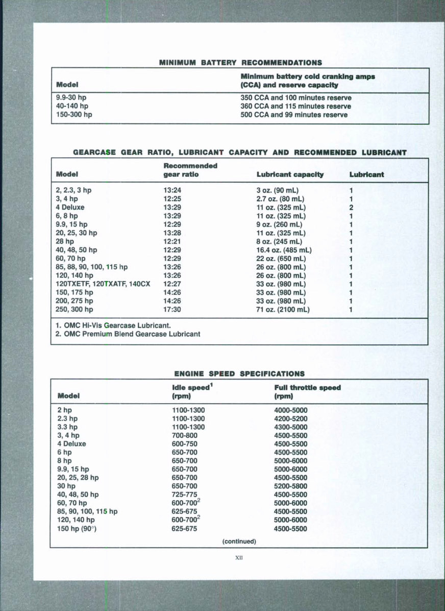
MINIMUM BATTERY RECOMMENDATIONS Model Minimum battery cold cranking amps and reserve capacity 9.9-30 hp 40-140 hp 150-300 hp 350 CCA and 100 minutes reserve 360 CCA and 115 minutes reserve 500 CCA and 99 minutes reserve GEARCASE GEAR Model 2, 2.3, 3 hp 3,4hp 4 Deluxe 6,8hp 9.9,15 hp 20, 25, 30 hp 28 hp 40,48, 50 hp 60, 70 hp 85,88,90,100,115 hp 120,140 hp RATIO, LUBRICANT Recommended gear ratio 13:24 12:25 13:29 13:29 12:29 13:28 12:21 12:29 12:29 13:26 13:26 120TXETF, 120TXATF, 140CX 12:27 150,175 hp 200, 275 hp 250,300 hp 14:26 14:26 17:30 1. OMC Hi-Vis Gearcase Lubricant. 2. OMC Premium Blend Gearcase Lubricant CAPACITY AND RECOMMENDED LUBRICANT Lubricant capacity 1 3 oz. (90 mL) 2.7 oz. (80 mL) 11 oz. (325 mL) : 11 oz. (325 mL) 9 oz. (260 mL) 11 oz. (325 mL) 8 oz. (245 mL) 16.4 oz. (485 mL) 22oz.(650mL) 26 oz. (800 mL) 26 oz. (800 mL) 33 oz. (980 mL) 33 oz. (980 mL) 33 oz. (980 mL) i 71 oz. (2100 mL) Lubricant 1 1 2 1 1 1 1 ENGINE SPEED SPECIFICATIONS Model 2hp 2.3 hp 3.3 hp 3, 4 hp 4 Deiuxe 6hp 8hp 9.9,15hp 20, 25, 28 hp 30 hp 40, 48, 50 hp 60, 70 hp 85,90,100,115 hp 120,140 hp 150hp(90°) Idle speed^ (rpm) 1100-1300 1100-1300 1100-1300 700-800 600-750 650-700 650-700 650-700 650-700 650-700 725-775 600-700^ 625-675 600-700^ 625-675 (continued) Full throttle speed (rpm) 4000-5000 4200-5200 4300-5000 4500-5500 4500-5500 4500-5500 5000-6000 5000-6000 4500-5500 5200-5800 4500-5500 5000-6000 4500-5500 5000-6000 4500-5500 XII
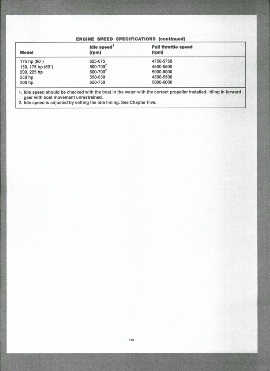
ENGINE SPEED SPECIFICATIONS (continued) Model 175hp(90°) 150,175 hp (60°) 200, 225 hp 250 hp 300 hp Idle speed^ (rpm) 625-675 600-700^ 600-700^ 550-650 650-750 1. Idie speed shouid be checked with the boat in the water with gear with boat movement unrestrained. 2. Idle speed is adjusted by setting the idie timing. See Chapter Full throttle speed (rpm) 4750-5750 4500-5500 5000-6000 4500-5500 5000-6000 the correct propelier instailed, idiing in forward Five. xm
Chapter One General Information This detailed, comprehensive manual contains complete information covering maintenance, repair and overhaul. Hundreds of photos and drawings guide you throughout every proce- dure. Troubleshooting, tune-up, maintenance and repair are not difficult if you know what tools and equipment to use and what to do. Anyone not afraid to get their hands dirty, of average in- telligence and with some mechanical ability can perform most ofthe procedures in this manual. See Chapter Two for more information on tools and techniques. A shop manual is a reference. You want to be able to find information quickly. Clymer books are designed with you in mind. All chapters are thumb tabbed and important items are indexed at the end ofthe manual. All procedures, tables, photos and instructions in this manual assume the reader may be working on the machine or us- ing the manual for the first time. Keep the manual in a handy place in your tool- box or boat. It will help you to better understand how your boat runs, lower repair and maintenance costs and generally increase your enjoyment of your boat. MANUAL ORGANIZATION This chapter provides general infonnation useful to boat owners and marine mechanics. Chapter Two discusses the tools and tech- niques for preventative maintenance, trouble- shooting and repair. Chapter Three provides troubleshooting and testing procedures for all systems and individual components. Following chapters describe specific systems, providing disassembly, inspection, assembly and adjustment procedures in simple step-by- step form. Specifications concerning a specific system are included at the end ofthe appropriate chapter.
CHAPTER ONE NOTES, CAUTIONS AND WARNINGS The terms NOTE, CAUTION and WARNING have specific meanings in this manual. A NOTE provides additional information to make a step or procedure easier or more clear. Disregarding a NOTE could cause inconvenience, but would not cause damage or personal injury. A CAUTION emphasizes areas where equip- ment damage could cause permanent mechani- cal damage; however, personal injury is unlikely. A WARNING emphasizes areas where per- sonal injury or even death could result from neg- ligence. Mechanical damage may also occur. WARNINGS must be taken seriously. In some cases, serious injury or death has resulted from disregarding similar warnings. TORQUE SPECIFICATIONS Torque specifications throughout this manual are given in foot-pounds (ft.-lb.), inch-pounds (in.-lb.) and newton meters (N»m.). Newton me- ters are being adopted in place of me- ter-kilograms (mkg) in accordance with the Intemational Modernized Metric System. Ex- isting torque wrenches calibrated in me- ter-kilograms can be used by performing a simple conversion: move the decimal point one place to the right. For example, 4.7 mkg = 47 N»m. This conversion is accurate enough for most mechanical operations even though the ex- act mathematical conversion is 3.5 mkg = 34.3 N»m. ENGINE OPERATION All marine engines, whether two or four-stroke, gasoline or diesel, operate on the Otto cycle of intake, compression, power and exhaust phases. Two-Stroke Cycle A two-stroke engine requires one crankshaft revolution (two strokes of the piston) to com- plete the Otto cycle. All engines covered in this manual are a two-stroke design. Figure 1 shows gasoline two-stroke engine operation. Four-Stroke Cycle A four-stroke engine requires two crankshaft revolutions (four strokes of the piston) to com- plete the Otto cycle. Figure 2 shows gasoline four-stroke engine operation. FASTENERS The material and design ofthe various fasten- ers used on marine equipment are careftiUy thought out and designed. Fastener design deter- mines the type of tool required to work with the fastener. Fastener material is carefully selected to decrease the possibility of physical failure or corrosion. See Galvanic Corrosion in this chap- ter for information on marine materials. Nuts, bolts and screws are manufactured in a wide range of thread patterns. To join a nut and bolt, the diameter ofthe bolt and the diameter of the hole in the nut must be the same. It is just as important that the threads are compatible. The easiest way to determine if fastener threads are compatible is to turn the nut on the bolt, or bolt into its threaded opening, using fin- gers only. Be sure both pieces are clean. If much force is required, check the thread condition on each fastener. If the thread condition is good but the fasteners jam, the threads are not compati- ble. Four important specifications describe the thread: 1. Diameter. 2. Threads per inch. 3. Thread pattern.
Upon purchasing this manual, you will receive a .PDF file containing an email contact. After contacting us, you will receive a reply with a link to access the manual for your 1993 Johnson Evinrude 100 HP 4 Cyl Outboard.
This comprehensive manual covers every aspect of your machine, providing detailed guidance on every nut and bolt. With hundreds of pages, it offers solutions for various issues, from simple tasks like an oil change to more complex procedures like a transmission swap. The manual includes numerous illustrations to assist you and features easy-to-understand text throughout.
Utilize the search function to navigate the manual efficiently and print the necessary pages as needed. This Factory Service Repair Manual is designed to walk you through the fundamentals of maintenance and repair, providing a step-by-step approach to equip you with the knowledge mastered by factory-trained technicians.
By leveraging the insights from this service repair manual, any owner can confidently make informed decisions regarding the maintenance and repair of their machine.
Rest assured, in addition to the high-quality service manual, we are committed to delivering excellent customer service, ensuring your satisfaction with your purchase.
Recently Viewed
5,521,897Happy Clients
2,594,462eManuals
1,120,453Trusted Sellers
15Years in Business
Price:
Actual Price:
1993 Johnson Evinrude 100 HP 4 Cyl Outboard Factory Service & Work Shop Manual