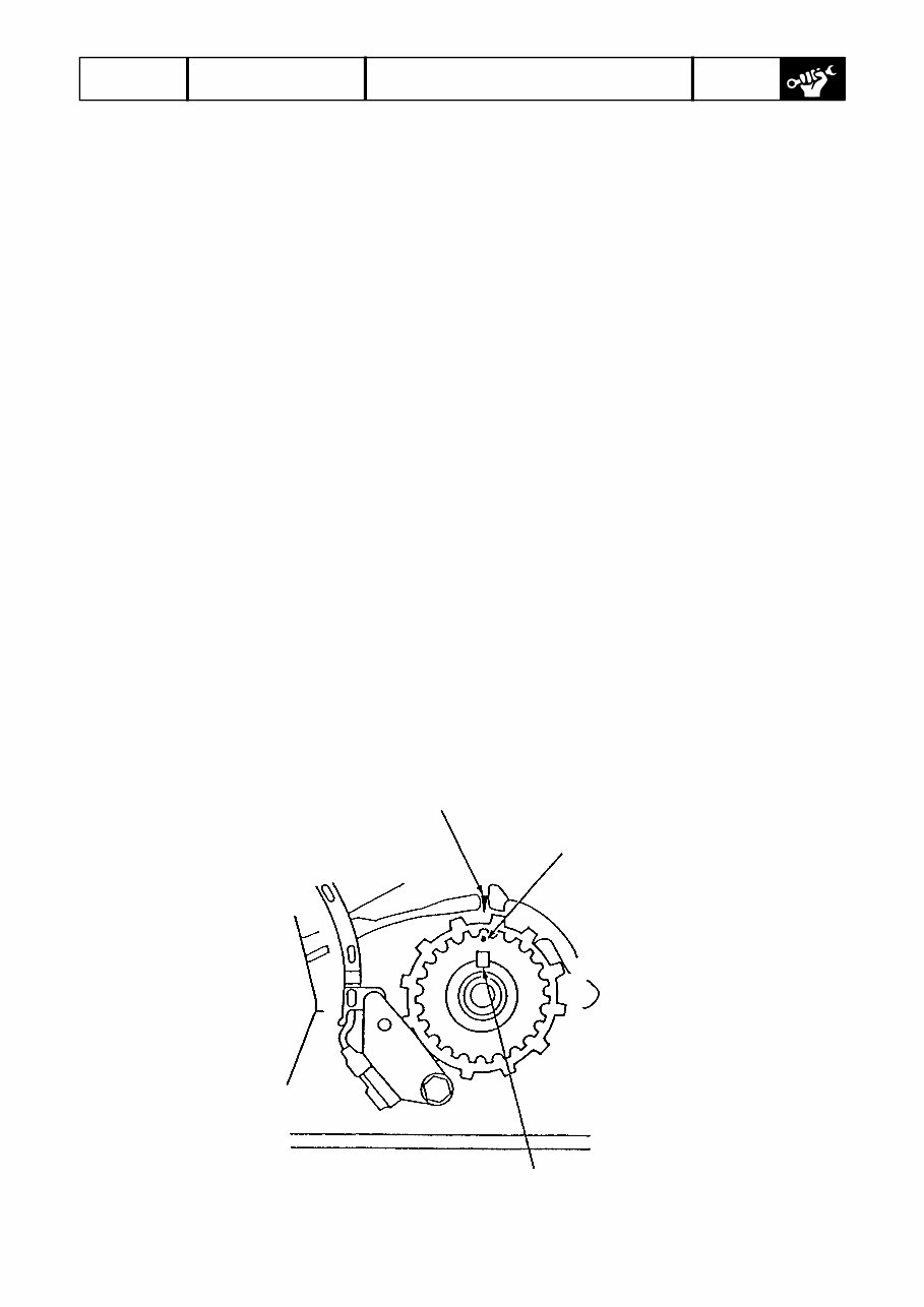
225021 RESOURCE 2002 BF200/225 2/57 Engine Tension Adjustment (0) Align No.1 TDC mark on the cam pulley with the alignment mark on the timing belt back cover. (1) Loosen the timing belt tensioner fastening bolts. (2) Turn the crankshaft counter-clockwise by six or more teeth of the timing belt drive pulley. (3) Turn the crankshaft clockwise by three teeth of the timing belt drive pulley. (4) Tighten the timing belt tensioner bolt to specified torque. CAUTION: • Adjust the belt tension when the engine is cold after valve clearance adjustment. • Leave the tensioner spring load-free during tension adjustment. Installation CAUTION: Before installation, be sure to wipe the upper and lower covers clean with a piece of waste cloth. (1) Remove all the spark plugs. (2) Align the TDC mark on the timing belt drive pulley with the alignment mark on the crankcase upper cover. Alignment mark Key TDC mark
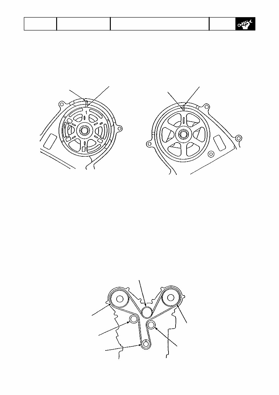
225021 RESOURCE 2002 BF200/225 3/57 (3) Align the TDC mark on the camshaft pulley at each bank with the alignment mark on the back cover. Left bank Right bank Alignment mark TDC mark Alignment mark TDC mark (4) Loosen the tension pulley fastening bolt by baking it off approximately 1 complete turn from the contact point of its bearing surface. (5) Install the timing belt on the pulleys in the following order. (A) Timing belt drive pulley (crankshaft) → (B) Idler pulley B (flangeless) → (C) Left-bank cam shaft pulley → (D) Idler pulley A (flanged) → (E) Tensioner pulley → (F) Right-bank camshaft pulley CAUTION: Install the timing belt using care not to damage it. (A) (E) (F) (D) (C) (B)
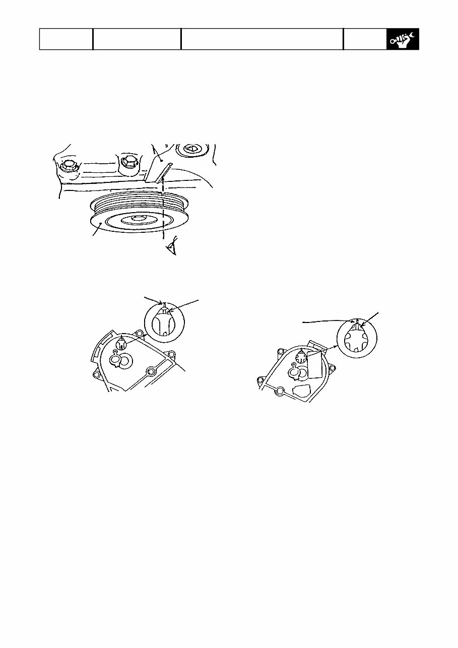
225021 RESOURCE 2002 BF200/225 4/57 (6) Check that the TDC marks on the timing belt drive pulley and cam shaft pulley are in alignment with the top-dead-center point of compression stroke of No. 1 piston. Crankcase Alignment mark (embossed line) Timing belt drive pulley Right-bank camshaft pulley Timing belt drive pulley Alignment mark (embossed line) on timing belt cover must be in alignment with TDC mark on cam pulley. TDC mark (camshaft pulley) Inspection hole Left-bank cam shaft pulley Alignment mark on timing belt cover TDC mark (camshaft pulley) Inspection hole (7) After the belt tension adjustment is completed, tighten the tensioner bolts to specified torque (36.3 – 42.1Nm). (8) Install the left-bank and right-bank timing belt covers. (9) Install the crankshaft pulley and tighten the pulley bolt to specified torque. Make the timing belt conform to the pulley by giving the crankshaft 5 to 6 turns. (10) Once again, check that the TDC marks on the timing belt drive pulley and camshaft pulley are in alignment with the top-dead-center position of compression stroke of No. 1 piston. (11) If the timing belt drive pulley and/or cam shaft pulley are not in alignment with No. 1 piston top-dead-center position, redo the installation of the timing belt on the pulleys from the beginning. NOTE: To remove the timing belt, follow the installation sequence in reverse.
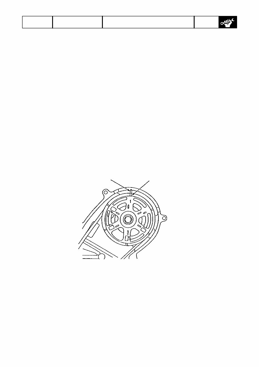
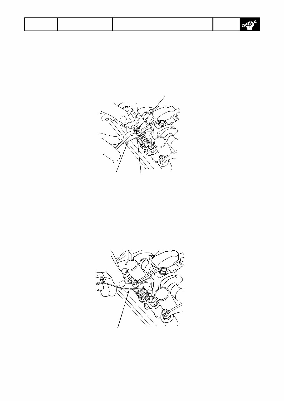
225021 RESOURCE 2002 BF200/225 5/57 Tappet Clearance Adjustment CAUTION: • Carry out the adjustment at normal temperature (10 – 40°C in oil temperature). • Adjust tappet clearance with each piston at the top-dead-center position of its compression stroke (both intake and exhaust rocker arms are not lifted). (1) Remove the engine cover and side cover. (2) Remove the rear bracket and stay. (3) Remove the silencer. (4) Remove the inlet manifold upper cover. (5) Remove the inlet manifold. (6) Remove the timing belt upper cover. (7) Position the camshaft pulley to the top dead center of compression stroke of No. 1 piston. NOTE: Align No.1 piston TDC mark with the alignment mark on the back cover. TDC mark Alignment mark
225021 RESOURCE 2002 BF200/225 6/57 (8) Loosen lock nut on each rocker arm adjust screw. Turning the adjust screw, adjust tappet clearance. [Standard tappet clearance] Intake: 0.20 – 0.24 mm Exhaust: 0.28 – 0.34 mm Locknut 7 x 0.75 mm 20 N·m (2.0 kgf·m, 14 lbf·ft) Adjusting screw Feeler gauge (9) Tighten the lock nut and measure the tappet clearance again with a feeler gauge. CAUTION: Be sure to use a torque wrench when tightening the lock nuts. Feeler gauge (10) Position the camshaft pulley to the top-dead-center points of compression stroke of other pistons, and repeat the steps (8) and (9).
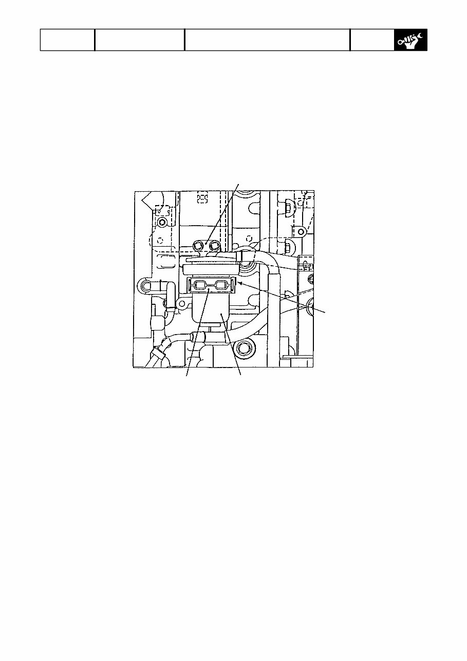
225021 RESOURCE 2002 BF200/225 19/57 (4) Return the control lever to the neutral position. (5) Turning the adjust nut on the close-side throttle cable, align the match mark and roller center on the throttle cam. (6) Tighten the throttle cable adjust nuts. CAUTION: If the control lever is stuck when the engine is not operating, shift it carefully while lightly turning the propeller or propeller shaft. An attempt to shift forcedly may damage the control system. Checking Water Separator with Water Level Sensor Remove the engine cover. Visually check the water separator cup. If water is collected and/or foreign matter are accumulated in the cup, disassemble and inspect the water separator. The same applies when “water filled” warning buzzer sounds. WARNING: During the work below, keep away from any heat source. Disassembly (1) Disconnect 2P coupler of the water level sensor. (2) Remove the suspension from the strainer bracket, then from the water separator. (3) Clip the fuel tube firmly not to let fuel out. (4) Remove the fuel tube. (5) Remove three screws holding the separator cup to the separator body, and separate them. (6) Remove water and foreign matters from inside the cup. Inspection Perform the steps (1) through (3) to check the water separator for abnormality. Replace the water separator if necessary. (1) With the separator cup off, check that the float moves smoothly. (2) With the separator cup off, check that there is no continuity between two terminals of 2P coupler when the water level sensor is maintained in the horizontal position. (3) With the separator cup off, check that there is continuity between two terminals of 2P coupler when the water level sensor is maintain upside down. (4) Check the O-ring sealing the cup and element for hairline fracture, crack and setting. Replace if necessary.
225021 RESOURCE 2002 BF200/225 20/57 Reassembly Follow the disassembly sequence in reverse. • Screw tightening torque: 3.4+/-0.7 Nm • Align the fuel joint (outlet side) of the strainer to the positioning mark of the suspension. • Check for fuel leakage after reassembly. Bracket Positioning mark Separator cup Suspension
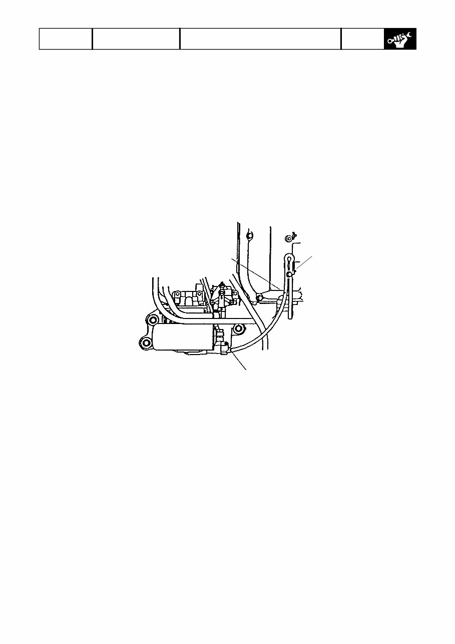
225021 RESOURCE 2002 BF200/225 21/57 Draining Fuel from Vapor Separator and Checking Vapor Separator WARNING: During the work below, keep away from any heat source. Draining Fuel (1) Disconnect the drain tube clamped at the bottom of the left-bank cylinder head cover, and put the tube end out to the front of the side cover. (2) Loosen the drain bolt of the vapor separator. Drain tube Clamp Drain bolt (3) Tilt up the outboard motor. (4) When fuel is drained from the drain tube, put the outboard motor back in the horizontal position. (5) After fuel has been drained out, tighten the drain bolt and clamp the drain tube securely to the cylinder head cover.
225021 RESOURCE 2002 BF200/225 22/57 Checking Low Pressure Fuel Strainer WARNING: During the work below, keep away from any heat source. Checking Remove the engine cover and visually check the cup of the low pressure strainer. If water is collected and/or foreign matters are accumulated in the cup, disassemble and clean the low pressured fuel strainer as follows. The same applies when the element is clogged. Disassembly and Cleaning (1) Remove the suspension from the strainer bracket, then from the strainer. (2) Clip the fuel tube not to let fuel out. (3) Remove the fuel tube. (4) Remove three screws holding the strainer cup to the strainer body, and separate them. (5) Remove water and foreign matters completely from the strainer cup. (6) If the element is clogged, replace it. (7) Check the O-ring sealing the cup and element for hairline fracture, crack and permanent set. Replace if necessary. Reassembly Follow the disassembly sequence in reverse. • Screw tightening torque: 3.4 ± 0.7 Nm • Make sure that the position of the strainer fuel joint (outlet side) matches the positioning mark on the suspension. • After reassembly, check that the strainer has no fuel leaks.
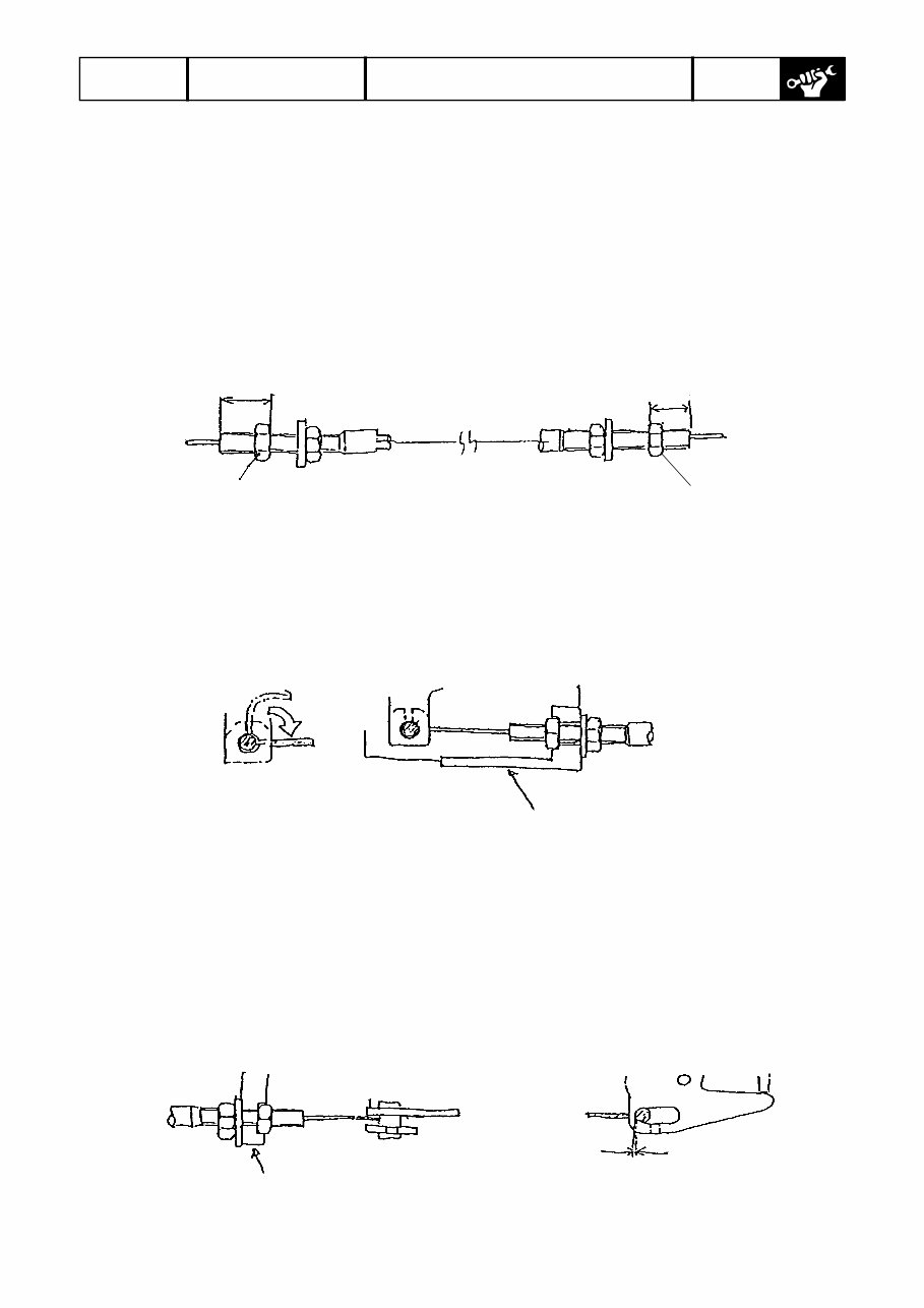
225021 RESOURCE 2002 BF200/225 31/57 Frame Adjustment of cover lock cables Perform the following adjustment steps with the underside cover removed. (1) Move the adjusting nuts on the cable ends A and B of the cover lock cable B (shorter cable) to the positions shown below. End A 16 mm End A 7 mm Adjusting nut Adjusting nut (2) Insert the hook of the cable extending from the end A of the cover lock cable B into the front lock arm, fit the end A in the groove of the front cover bracket, then tighten the washer- attached nut to secure the end A on the bracket. End A secured on bracket Front cover bracket (3) Insert the hook of the cable extending from the end B of the cover lock cable B into the slot in the left side lock arm, fit the end B in the groove of the side cover bracket, then tighten the washer-attached nut to secure the end B on the bracket. NOTE: There should be no gap between the cable hook and the left edge of the slot in the side lock arm. If there is a gap, make an adjustment by turning the nuts. Side cover bracket Gap 0 mm
The 2002 Honda 200HP, 225HP Outboards (BF200, BF225) Service & Repair Manual is the breakdown for two of Honda’s most trusted big-block four-strokes. These engines are built to last, but when it’s time to roll up your sleeves—whether it’s a mid-season tune-up or a full teardown—this manual gives you the step-by-step structure needed to get things done right the first time.
You’ll find detailed service instructions for valve clearance adjustments, timing belt replacement, gearcase inspection, cooling system maintenance, fuel injector servicing, and more. Every section includes factory torque specs, tolerances, and mechanical procedures that don’t assume you’re guessing—because on the dock or in the shop, you can’t afford guesswork.
This manual is written like the tech at the marina who actually knows their stuff—no filler, no sales pitch, just real procedures for people who'd rather fix it than float around waiting for help. If your BF200 or BF225 needs attention, this is where you start.
Printable: Yes Language: English Compatibility: Pretty much any electronic device, incl. PC & Mac computers, Android and Apple smartphones & tablet, etc. Requirements: Adobe Reader (free)

![Honda Marine BF200/225 Service Manual [ENG]](https://cdm.emanualonline.com/media/catalog/product/cache/518e89fe08903fc357b0d05eb410bb22/4/8/489847-1.jpg "Honda Marine BF200/225 Service Manual [ENG]")