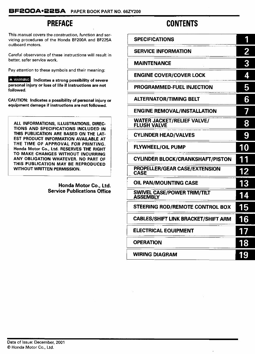
Honda BF200A/BF225A (200/225HP) Outboards OEM Service & Repair Manual
What's Included?
Lifetime Access
Fast Download Speeds
Online & Offline Access
Access PDF Contents & Bookmarks
Full Search Facility
Print one or all pages of your manual
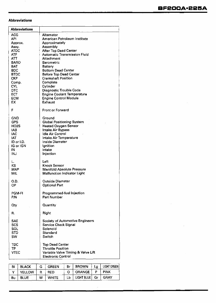
Abbreviations ___ ~ BI BLACK G GREEN Br BROWN Lg LIGHTGREEN Y YELLOW R RED 0 ORANGE P PINK Bu BLUE W WHITE Lb LIGHTBLUE Gr GRAY Abbreviations ACG API Approx. Assy. ATDC ATF AT BAR0 BAT BDC BTDC CKP Comp. CYL DTC ECT ECM EX F GND GPS H02S IAB IAC IAT ID or I.D. IG or IGN IN INJ L. KS MAP MIL O.D. OP PGM-FI PIN Qtv R. SAE scs SOL STD sw TDC TP VTEC ~~~~~~~ ~ Alternator American Petroleum Institute Approximately Asse m b I y After Top Dead Center Automatic Transmission Fluid Attachment Barometric Battery Bottom Dead Center Before Top Dead Center Crankshaft Position Complete Cylinder Diagnostic Trouble Code Engine Coolant Temperature Engine Control Module Exhaust Front or Forward Ground Global Positioning System Heated Oxygen Sensor Intake Air Bypass Idle Air Control Intake Air Temperature Inside Diameter Ignition Intake Injection Left Knock Sensor Manifold Absolute Pressure Malfunction Indicator Light Outside Diameter Optional Part Programmed-fuel Injection Part Number Quantity Right Society of Automotive Engineers Service Check Signal Solenoid Standard Switch Top Dead Center Throttle Position Variable Valve Timing &Valve Lift Electronic Control
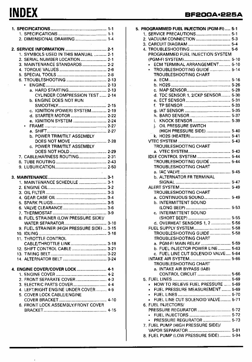
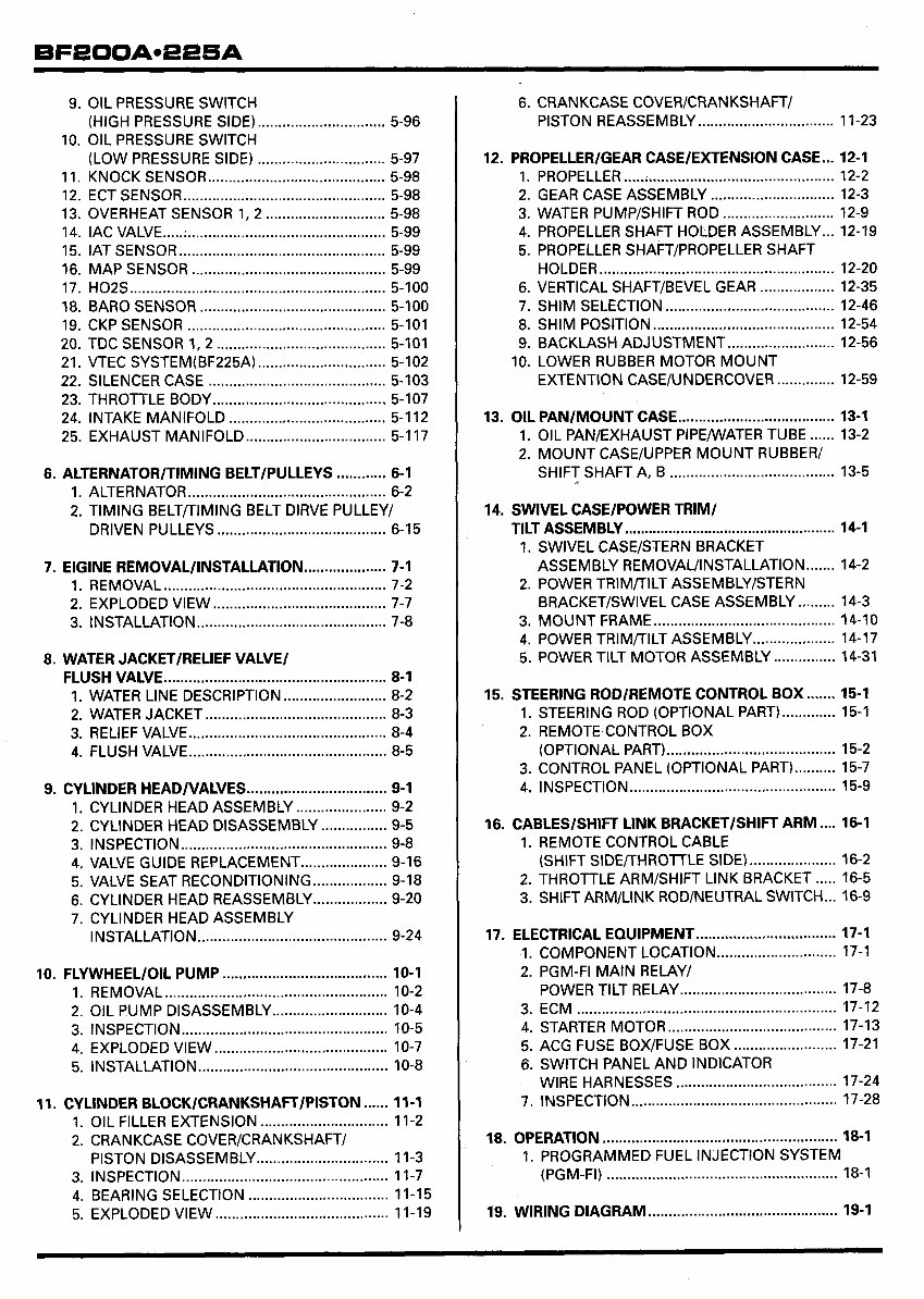
INDEX 1 . SPECIFICATIONS ................................................. 1-1 1 . SPECIFICATIONS .......................................... 1-1 2 . DIMENSIONAL DRAWING ........................... 1-4 2 . SERVICE INFORMATION .................................... 2-1 1 . SYMBOLS USED IN THIS MANUAL ........... 2-1 2 . SERIAL NUMBER LOCATION ....................... 2-1 3 . MAINTENANCE STANDARDS ..................... 2-2 4 . TORQUE VALUES ......................................... 2-6 5 . SPECIAL TOOLS ........................................... 2-8 6 . TROUBLESHOOTING ................................... 2-13 ENGINE ..................................................... 2-13 a . HARD STARTING ................................. 2-13 b . ENGINE DOES NOT RUN CYLINDER COMPRESSION TEST ...... 2-14 SMOOTHLY .......................................... 2-15 c . IGNITION (POWER) SYSTEM ............. 2-19 d . STARTER MOTOR ............................... 2-22 e . IGNITION SYSTEM ............................. 2-24 a . SHIFT .................................................... 2-27 b . POWER TRIMflILT ASSEMBLY c . POWER TRlMfllLT ASSEMBLY FRAME ...................................................... 2-27 DOES NOT MOVE ............................... 2-28 DOES NOT HOLD ................................ 2-29 7 . CABLE/HARNESS ROUTING ........................ 2-31 8 . TUBE ROUTING ............................................ 2-43 9 . LUBURICATION ............................................. 2-50 3 . MAINTENANCE ................................................... 3-1 1 . MAINTENANCE SCHEDULE ........................ 3-1 2 . ENGINE OIL ................................................... 3-2 3 . OIL FILTER ..................................................... 3-3 4 . GEAR CASE OIL ............................................ 3-4 5 . SPARK PLUGS ............................................... 3-5 6 . VALVE CLEARANCE ...................................... 3-6 7 . THERMOSTAT ............................................... 3-9 8 . FUEL STRAINER (LOW PRESSURE SIDE)/ WATER SEPARATOR ..................................... 3-10 9 . FUEL STRAINER (HIGH PRESSURE SIDE) ... 3-15 I0 . IDLING ........................................................... 3-16 11 . THROTTLE CONTROL CABLEflHROTTLE LINK ............................... 3-18 12 . SHIFT CONTROL CABLE .............................. 3-21 13 . TIMING BELT ................................................. 3-22 14 . ALTERNATOR BELT ...................................... 3-24 4 . ENGINE COVER/COVER LOCK .......................... 4-1 1 . ENGINE COVER ............................................ 4-2 2 . FRONT SEPARATE COVER ........................... 4-3 3 . ELECTRIC PARTS COVER ............................. 4-4 4 . LEFT/RIGHT ENGINE UNDER COVER ......... 4-5 5 . COVER LOCK CABLE/ENGINE 6 . FRONT LOCK ASSEMBLY/FRONT COVER COVER BRACKET .......................................... 4-10 BRACKET ....................................................... 4-15 5 . PROGRAMMED FUEL INJECTION (PGM-FI) ..... 5-1 1 . SERVICE PRECAUTIONS .............................. 5-1 2 . VACUUM CONNECTtON .............................. 5-3 3 . CARCUIT DIAGRAM ..................................... 5-4 4 . TROUBLESHOOTING ................................... 5-6 PROGRAMMED FUEL INJECTION SYSTEM (PGM-FI SYSTEM) ......................................... 5-10 ECM TERMINAL ARRANGEMENT .......... 5-10 TROUBLESHOOTING GUIDE .................. 5-14 TROUBLESHOOTING CHART a . ECM ...................................................... 5-16 b . H02S .................................................... 5-26 c . MAP SENSOR ...................................... 5-28 d . TDC SENSOR 1. 2/CKP SENSOR ........ 5-30 e . ECT SENSOR ....................................... 5-31 f . TP SENSOR ......................................... 5-33 g . IAT SENSOR ........................................ 5-35 h . BAR0 SENSOR .................................... 5-37 i . KNOCK SENSOR ................................. 5-39 j . OIL PRESSURE SWITCH (HIGH PRESSURE SIDE) ..................... 5-40 k . H02S (HEATER) ................................... 5-41 VTEC SYSTEM .............................................. 5-43 TROUBLESHOOTING CHART a . VTEC SYSTEM ..................................... 5-43 IDLE CONTROL SYSTEM ............................. 5-44 TROUBLESHOOTtNG GUIDE .................. 5-44 TROUBLESHOOTING CHART a . IAC VALVE ............................................ 5-45 b . ALTERNATOR FR TERMINAL SIGNAL ................................................ 5-47 ALERT SYSTEM ............................................ 5-49 TROUBLESHOOTING CHART a . CONTINUOUS SOUND ....................... 5-49 b . INTERMITTENT SOUND c . INTERMITTENT SOUND (LONG BEEP) ....................................... 5-53 (SHORT BEEP) ..................................... 5-55 d . OVERHEAT SENSORS 1. 2 ................. 5-56 FUEL SUPPLY SYSTEM ................................ 5-58 TROUBLESHOOTING GUIDE .................. 5-58 TROUBLESHOOTING CHART PGM-FI MAIN RELAY .......................... 5-59 b . FUEL INJECTOR POWER LINE ........... 5-63 c . FUEL LINE CUT SOLENOID VALVE .... 5-64 INTAKE AIR SYSTEM .................................... 5-66 a . TROUBLESHOOTING CHART a . INTAKE AIR BYPASS (IAB) CONTROL CIRCUIT ............................. 5-66 5 . FUEL LINES ................................................... 5-69 HOW TO RELIEVE FUEL PRESSURE ...... 5-69 FUEL PRESSURE MEASUREMENT ........ 5-69 FUEL LINES .............................................. 5-70 FUEL LINE CUT SOLENOID VALVE ......... 5-71 PRESSURE REGURATOR ............................. 5-72 FUEL INJECTORS .................................... 5-72 PRESSURE REGURATOR ........................ 5-73 7 . FUEL PUMP (HIGH PRESSURE SIDE)/ VAPOR SEPARATOR ..................................... 5-81 8 . FUEL PUMP (LOW PRESSURE SIDE) .......... 5-94 6 . FUEL INJECTORS/
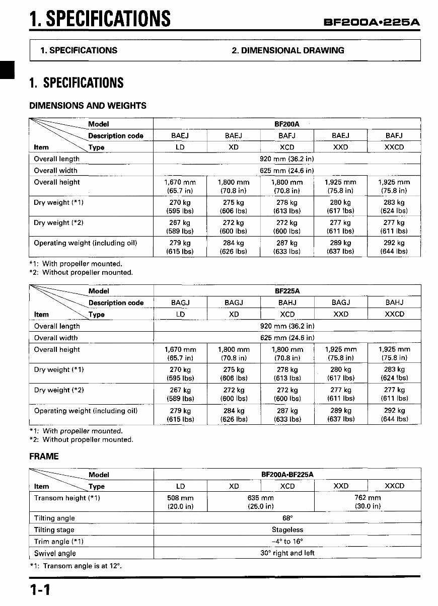
1. SPECIFICATIONS Description code I 1. SPECIFICATIONS 2. DIMENSIONAL DRAWING BFZOOA BAEJ BAEJ BAFJ BAEJ BAFJ LD XD XCD XXD XXCD I 1. SPECIFICATIONS I' LD XD XCD XXD DIMENSIONS AND WEIGHTS XXCD Transom height ("I) Tilting angle Tilting stage Trim anale ("1) I Overall length I 920 mm (36.2 in) I 508 mm 635 mm 762 mm (20.0 in) (25.0 in) (30.0 in) 68" Stageless -4" to 16" I Overall width I 625 mm (24.6 in) I Swivel angle Overall height ~~~~ 30" right and left 1,670 mm 1,800 mm I (65.7 in) I (70.8 in) 1,800 mm 1,925 mm 1,925 mm (70.8 in) I (75.8 in) 1 (75.8 in) I Dry weight ("1) Dry weight ("2) Operating weight (including oil) 270 kg 275 kg (595 Ibs) (606 Ibs) 267 kg 272 kg ! (589 Ibs) (600 Ibs) 279 kg 284 kg (615 Ibs) 1 (626 Ibs) 278 kg 280 kg (613 Ibs) 1 (617 Ibs) ~~ 272 kg 277 kg (600 Ibs) I (611 Ibs) 287 kg 289 kg (633 Ibs) 1 (637 Ibs) 283 kg (624 Ibs) 277 kg (611 Ibs) 292 kg (644 Ibs) "I: With propeller mounted. "2: Without propeller mounted. (626 Ibs) I (633 Ibs) I (637 Ibs) I (644 Ibs) "I: With propeller mounted. "2: Without propeller mounted. FRAME 1-1
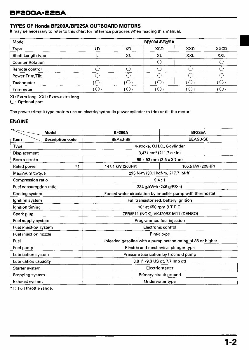
TYPES OF Honda BF200A/BF225A OUTBOARD MOTORS It may be necessary to refer to this chart for reference purposes when reading this manual. Model BF200A-BF225A Type Shaft Length type Counter Rotation Remote control Power Trimflilt LD XD XCD XXD XXCD L XL XL XXL XXL 0 0 0 0 0 0 0 0 0 0 0 0 XL: Extra long, XXL: Extra-extra long (-1: Optional part Tachometer Trimmeter The power trim/tiIt type motors use an electric/hydraulic power cylinder to trim or tilt the motor. (0) (0) (0) (0, (0, (0) (0) (0) (0, (0, ENGINE ~ Model DescriDtion code ~ ~ ~ ~ BF200A BF225A BEAEJ-SE BEAGJ-SE 4-st roke, 0.H .C., 6-cvlinder I I Displacement Bore x stroke Rated power "1 Maximum torque Compression ratio 3,471 cm3(21 1.7 cu in) 89 x 93 mm (3.5 x 3.7 in) 147.1 kW (200HP) 165.5 kW (225HP) 295 N*m (30.1 kgf-m, 217.7 IbfW 9.4: 1 Fuel consumption ratio Coolina svstem 334 g/kW*h (246 g/PS*h) Forced water circulation bv imDeller Durn13 with thermostat I Lubrication svstem I Pressure lubrication bv trochoid DumD I Ignition system Ignition timing Spark plug Fuel supply system Fuel injection system Fuel injection nozzle Fuel 1 FuelDUmD Full transistorized, battery ignition 10" at 650 rpm B.T.D.C. Programmed fuel injection Electronic control Pintle type Unleaded gasoline with a pump octane rating of 86 or higher Electric and mechanical Dlunaer tvDe IZFR6F1 1 (NGK), VKJPORZ-MI 1 (DENSO) Lubrication capacity Starter svstem 1-2 8.8 i? (9.3 US qt, 7.7 Imp qt) Electric starter Stopping system Exhaust system Primary circuit ground Underwater type
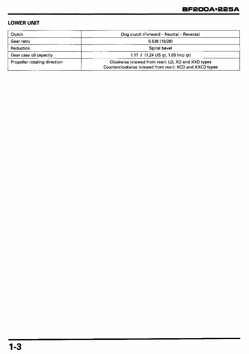
LOWER UNIT Clutch Gear ratio Reduction Gear case oil capacity Propeller rotating direction Dog clutch (Forward - Neutral - Reverse) 0.536 (1 5/28) Spiral bevel 1.17 P (1.24 US qt, 1.03 Imp qt) Clockwise (viewed from rear): LD, XD and XXD types Counterclockwise (viewed from rear): XCD and XXCD types 1-3
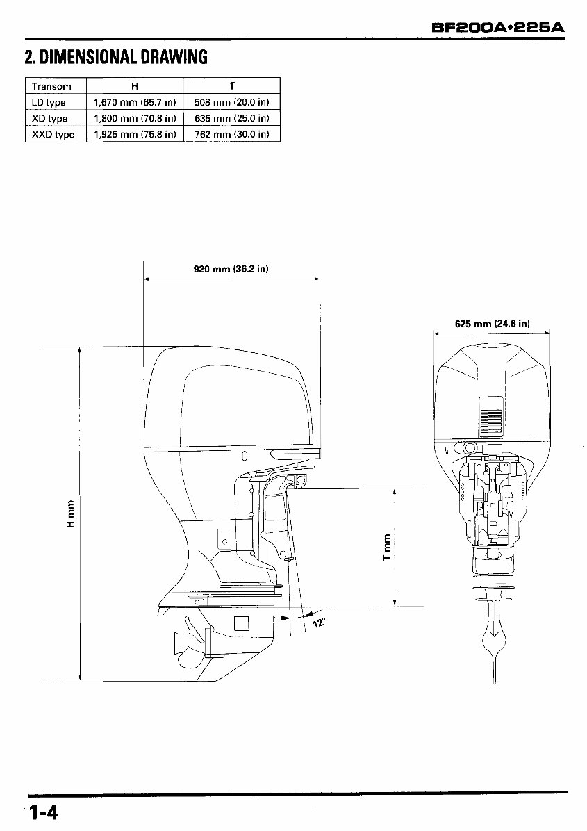
2. DIMENSIONAL DRAWING Transom LD type XD type XXD tvDe H T 1,670 rnm (65.7 in) 1,800 mm (70.8 in) 1,925 mm (75.8 in) 508 rnm (20.0 in) 635 rnm (25.0 in) 762 rnm (30.0 in) E E I 920 mm (36.2 in) d ll I 625 mm (24.6 in) w 1-4
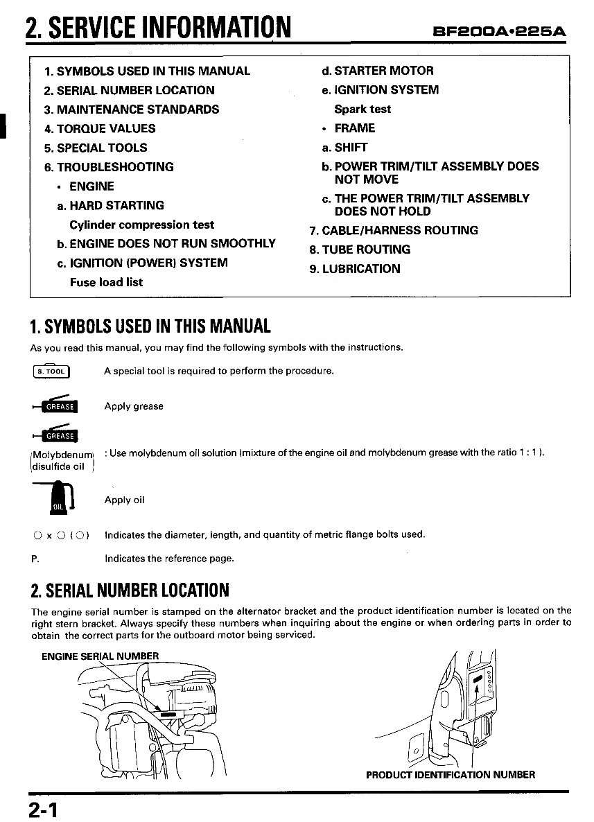
2, SERVICE INFORMATION BF2OOAe22SA 1. SYMBOLS USED IN THIS MANUAL 2. SERIAL NUMBER LOCATION 3. MAINTENANCE STANDARDS 4. TORQUE VALUES 5. SPECIAL TOOLS 6. TROUBLESHOOTING ENGINE a. HARD STARTING Cylinder compression test b. ENGINE DOES NOT RUN SMOOTHLY c. IGNITION (POWER) SYSTEM Fuse load list d. STARTER MOTOR e. IGNITION SYSTEM Spark test FRAME a. SHIFT b. POWER TRIM/TILT ASSEMBLY DOES c. THE POWER TRIM/TILT ASSEMBLY NOT MOVE DOES NOT HOLD 7. CABLE/HARNESS ROUTING 8. TUBE ROUTING 9. LUBRICATION 1. SYMBOLS USED IN THIS MANUAL As you read this manual, you may find the following symbols with the instructions. [GI A special tool is required to perform the procedure. Apply grease : Use molybdenum oil solution (mixture of the engine oil and molybdenum grease with the ratio 1 : 1 1. Apply oil 3 0 x 0 ( 0) Indicates the diameter, length, and quantity of metric flange bolts used. P. Indicates the reference page. 2. SERIAL NUMBER LOCATION The engine serial number is stamped on the alternator bracket and the product identification number is located on the right stern bracket. Always specify these numbers when inquiring about the engine or when ordering parts in order to obtain the correct parts for the outboard motor being serviced. ENGINE SERIAL NUMBER PRODUCT IDENTIFICATION NUMBER 2-1
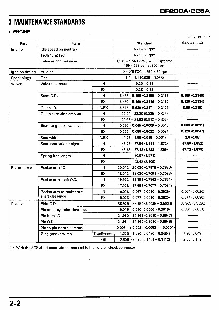
ENGINE Trolling speed Cylinder compression At idle*' Gap Valve clearance IN EX Unit: mm (in) 650 2 50 rpm 1,373 - 1,569 kPa (1 4 - 16 kgf/cm2, 199 - 228 psi) at 300 rpm 10 2 2"BTDC at 650 2 50 rpm 1.0 - 1.1 (0.039 - 0.043) 0.20 - 0.24 0.28 - 0.32 Ignition timing Guide extrusion amount Stem-to-guide clearance Seat width I Spark plugs IN EX 21.20 - 22.20 (0.835 - 0.874) 20.63 - 21.63 (0.812 - 0.852) IN 0.020 - 0.045 (0.0008 - 0.0018) 0.080 (0.0031) EX 0.065 - 0.080 (0.0022 - 0.0031) 0.120 (0.0047) IN/EX 1.25 - 1.55 (0.049 - 0.061) 2.0 (0.08) Valves Seat installation height Rocker arms IN 46.75 - 47.55 (1.841 - 1.872) 47.80 (1.882) EX 46.68 - 47.48 (1.838 - 1.869) 47.73 (1.879) Pistons r Spring free length Rocker arm I.D. Rocker arm shaft O.D. Rocker arm-to-rocker arm shaft clearance 50.07 (1.971 ) - IN EX 53.48 (2.106) IN EX IN EX 20.012 - 20.030 (0.7879 - 0.7886) 18.012 - 18.030 (0.7091 - 0.7098) 19.972 - 19.993 (0.7863 - 0.7871) 17.976 - 17.994 (0.7077 - 0.7084) IN 0.026 - 0.067 (0.0010 - 0.0026) 0.067 (0.0026) EX 0.026 - 0.077 (0.0010 - 0.0030) 0.077 (0.0030) Idle speed (in neutral) I 650 & 50 rpm I I Pin bore I.D. Pin O.D. Pin-to-pin bore clearance Ring groove width TopISecond Oil 21.960 - 21.963 (0.8645 - 0.8647) 21.961 - 21.965 (0.8646 - 0.8648) -0.005 - + 0.002 (-0.0002 - + 0.0001) 1.220 - 1.230 (0.0480 - 0.0484) 2.805 - 2.825 (0.1104 - 0.11 12) 1.25 (0.049) 2.85 (0.112) Stem O.D. I IN I 5.485 - 5.495 (0.2159 - 0.2163) I 5.455 (0.2148) I I EX I 5.450 - 5.460 (0.2146 - 0.2150) I 5.420 (0.2134) I Guide I.D. I IN/EX I 5.515 - 5.530 (0.2171 - 0.2177) I 5.55 10.219) I Skirt O.D. I 88.975 - 88.985 (3.5029 - 3.5033) I 88.965 (3.5026) I Piston-to-cylinder clearance I 0.015 - 0.040 (0.0006 - 0.0016) I 0.080 (0.0031) I *I: With the SCS short connector connected to the service check connector. 2-2
Get instant access to the Honda BF200A/BF225A (200/225HP) Outboards OEM Service & Repair Manual without any extra fees or expiry dates. This Professional Manual is designed for both expert mechanics and technicians, as well as DIY enthusiasts. It provides complete coverage of repairs, servicing, and troubleshooting procedures with detailed photos, diagrams, step-by-step instructions, and highly detailed exploded diagrams to ensure every repair and service job is performed accurately.
Print a single page or the entire manual at your convenience. This manual can be used on multiple computers without any limitations or trial periods, and it does not require any renewal fees. It is fully compatible with all Windows and MAC computers. Key features include:
OEM Service & Repair information tailored for Honda BF200A/BF225A (200/225HP) Outboards
Comprehensive procedures for troubleshooting and repairs
Detailed photos, diagrams, and exploded views for easy reference
User-friendly format for both professional applications and home use
Recently Viewed
5,521,897Happy Clients
2,594,462eManuals
1,120,453Trusted Sellers
15Years in Business
Price:
Actual Price:
Honda BF200A/BF225A (200/225HP) Outboards OEM Service & Repair Manual