1964-1999 Force Outboard Motors OEM Service & Repair Manual
What's Included?
Lifetime Access
Fast Download Speeds
Offline Viewing
Access Contents & Bookmarks
Full Search Facility
Print one or all pages of your manual
Contents Table of Contents ………………………………………………………………. 1 Introduction and Safety Notice ……………………………………………….. 2 General Troubleshooting Information Recommended Marine Shop Electrical Test Equipment and Tools ………………………. 3 Tricks to Testing with Minimal Test Equipment ………………………………………….. 4 Voltage Drop Measurement………..………….…….…….….………………….………… 5 Johnson/Evinrude Model to Year Identification for 1980 and Up Engines ………………. 5 Engine Wiring Cross Reference Chart……………………………………………………. 6 ABYC Color Chart ………………………………………………………………………. 7 Chrysler Troubleshooting Battery CD Ignitions…………………………………………………………………….… 8 Magnapower II Ignitions…..……………………………………………………………… 9 Capacitive Discharge Ignitions with Alternator………………………………………….. 10-12 Force Troubleshooting Alternator Driven Ignitions (Prestolite)………………………………………………….. 13-16 Alternator Driven Ignitions (Brunswick)………………………………………………… 17-20 Johnson/Evinrude Troubleshooting Battery CD Ignitions…………………………………………………………………….... 21-22 Alternator Driven Ignitions 1972-78 W/Screw Terminal Power Packs………………..... 23-25 Alternator Driven Ignitions 1978-99…………………………………………………….. 26-31 60 Optical 6 Cylinder engines…………………………………………………………… 32-35 60 Optical 4 Cylinder engines…………………………………………………………… 36-39 Mercury Troubleshooting Battery CD Ignitions W/Points………………………………………………………….. 40 Battery CD Ignitions W/O Points……………………………………………………….. 41-44 Alternator Driven Ignitions…………………………………………………………….... 45-55 Mercury/Force CDM Ignitions System Troubleshooting 2 Cylinder CDM Ignitions …………………………………………………….…………. 56 3 Cylinder CDM Ignitions ……………………………………………………………….. 57 4 Cylinder CDM Ignitions …………………………………………………….…………. 58 6 Cylinder CDM Ignitions …………………………………………………….………….. 59-60 Appendix DVA (Peak Voltage) and Resistance Charts (Introduction)………………………………. 61 Chrysler DVA and Resistance Charts……………………………..……………………… 62 Force DVA and Resistance Charts……………………………………….………………. 63 Johnson/Evinrude DVA and Resistance Charts …………………….……………………. 64-65 OMC Sea Drive DVA and Resistance Charts ……………………………………………. 66 Mercury DVA and Resistance Charts…………………………………………………….. 67-69 Yamaha DVA and Resistance Charts…………………………………………………….. 70-75 Glossary of Terms …….………………………………………………………………….. 76 CDI Technical Service Bulletin OMC 3 Cyl 60, 65 and 70 HP engines ............................ 77 Force Engine wiring diagrams …………………………………………………………… 78-80 Johnson/Evinrude QuickStart Flywheel Trigger Magnet Orientation …………………… 81 OMC Stern Drive Electronic Shift Assist Applications and Wiring Diagrams ………….. 82-84 Troubleshooting Guide Rev B – 7 July 2006
3 Recommended Marine Shop Electrical Test Equipment and Tools The following is a listing of tools available from CDI Electronics and recommended for testing late model engines: Part Number Description Remarks/Use 511-9764 Neon Spark Tester Sealed single cylinder has removable ground clamp can be used for running tests 511-9766 Sealed Spark Gap Tester Allows for testing up to 8 cylinder for cranking tests. Sealed design reduces the chance of engine fire. 511-9770 Piercing Probes Allows access to wires for testing without removing the connection. Tiny hole usually reseals itself. 511-9773 DVA (Peak Voltage)Adapter Unit automatically compensates for polarity. Can be . used with most quality Multimeters 511-9775 Load Resistor Used to load the output of ignition modules when testing ignition coils. 518-33A CDI 33 Meter Meter has voltage, amperage, diode check and ohms Includes 511-9773 DVA Adapter DVA Adapter allows meter to read peak voltage 518-80TK Fluke Temperature Adapter Works with most digital Multimeters capable of reading millivolts. 520-ST80 DC Inductive Timing Light DC Powered timing light with a very bright strobe light. 551-33GF Gearcase Filler w/Check Valve Universal design makes filling lower units easier. Check valve assembly helps prevent oil spills and makes filling easier. 551-34PV Pressure/Vacuum Tester Repairable metal combination unit does both vacuum and pressure testing. 551-5110 Flywheel Holder Longer handle helps during use. 551-9765 Spark Plug Wire Puller Grounded design reduces the chances of shocking. 553-2700 Amphenol Pin Tool Set Set contains 1 each of 553-2697 (Insertion), 553-2698 (Pin Removal) and 553-2699 (Socket Removal) 553-9702 Sensor Gap Gauge Tool Used to set the timer-base air gap on 1973-1978 OMC 3 and 4 cylinder engines with screw terminal power packs. 554-9706 Amp Pin Removal Tool Used to remove the connector pins in the ignition system on Chrysler/Force engines using the Prestolite type ignitions. Also used on the Mercury TPI sensor connectors. 911-9783 Bullet Connector Kit Contains 10 pieces each of the male, female and sleeves. 912-9708 Marine Terminal Kit Contains 100+ pieces of hard to find terminals and heat shrink. 991-9705 Dielectric Grease Use to keep water and corrosion out of connectors. 511-6996 Remote Starter For OMC Used to replace the boat-side harness for engine testing, Fits most OMC engines 1969 to 2000. 511-7900 Remote Starter for Mercury Used to replace the boat-side harness for engine testing, Fits most Mercury engines 1979 to 2000. 519-LB85 Load Bank Used to load the battery when testing the battery charging output. Optional Equipment 511-4017 OMC Optical Sensor Tester Unique handheld tester that will efficiently test the optical ignition sensor. 511-0401 CDI 2 Cylinder Ignition Tester New hand-held ignition tester generates high-voltage stator and low voltage trigger signals to test a variety of 2 cylinder ignition systems. Engine specific adapters are required. Includes 511-0402, 511-0403 and 511-0404 adapters. 520-ST84 Ferret Ultra Bright Timing Light Ultra bright timing light is visible in bright sunlight. Also has a built-in tachometer for 2 and 4 stroke engines. This feature is a valuable diagnostic tool when troubleshooting ignition system problems.
4 Tricks to Testing with Minimal Test Equipment All Engines Please keep detailed records when you repair an engine. If an engine comes in with one cylinder not firing, mark which one on the work order/history. Intermittent Firing: This problem can be very hard to isolate. A good inductive tachometer can be used to compare the RPM on all cylinders up through WOT (wide-open throttle). A significant difference in the RPM readings can help pinpoint a problem quickly. Visually Check the Stator, Trigger, Rectifier/Regulator and Flywheel: Cracks, burned areas and bubbles in or on the components indicate a problem. If the battery charge windings on the stator are dark brown, black or burned on most or all of the posts, the rectifier/regulator is likely shorted as well. Any sign of rubbing on the outside of the stator indicates a problem in the upper or lower main bearings. A cracked trigger or outer charging magnets can cause many problems ranging from misfiring to no fire at all. Loose flywheel magnets can be dangerous, check the tightness of the bonding adhesive. Rectifier/Regulators can cause problems ranging from a high-speed miss to a total shutdown. An easy check is to disconnect the stator leads to the rectifier (Make sure to insulate them) and retest. If the problem is gone – replace the rectifier/regulator. Johnson/Evinrude Open Timer Bases: When all cylinders fire with the spark plugs out, but will not with them installed, try re-gapping the sensors using P/N: 553-9702 Gap Gauge. (See the section on OMC ADI Ignitions page 22-24). Engines with S.L.O.W. Features: If the customer is complaining that the engine won’t rev up and shakes real bad, the S.L.O.W. function could be activating. If the engine is NOT overheating, a temperature sensor or VRO sensor failing early can cause this problem. Disconnect the TAN wires at the power pack and retest. If the engine performs normally, reconnect the tan wires one at a time until the problem recurs, then replace the last sensor you connected. Make sure that all of the TAN wires are located as far as possible from the spark plug wires. Also check the blocking diode in the engine harness. Mercury 6 Cylinder Engines with ADI Ignitions If more than one cylinder is not firing: Replace BOTH switch boxes unless you can pin the problem down to the trigger. Replacing just one switch box can result in damage to the engine if the remaining switch box on the engine has a problem in the bias circuit. Always check the bias circuit: Disconnect the White/Black jumper between the switch boxes and check the resistance from the White/Black terminal on each switch box to engine ground. You should read 12-15,000 ohms on stock switch boxes, and 9,000-9,800 ohms on racing switch boxes. MAKE SURE THE READING IS THE SAME ON BOTH SWITCH BOXES! Any problem with the bias circuit and BOTH switch boxes must be replaced as a set. No Fire on 1, 3, 5 or 2, 4, 6: Swap the stator leads from one switch box to the other. If the problem moves, replace the stator. If the problem remains on the same cylinders, replace the switch box. If the stator is replaced and the problem is still present, try another flywheel. No Fire on One Cylinder: This can be caused by a defective blocking diode in the other switch box. Disconnect the White/Black jumper between the switch boxes and retest. If all cylinders are now firing, replace the switch box that was originally firing all three cylinders. To verify this condition, swap the trigger leads on the switch box that was originally firing all three cylinders. If the misfire moves to another cylinder, the switch box is bad.
5 Voltage Drop Measurement Start by using a good digital auto-ranging voltmeter capable of reading 1/10 th of a volt. The use of an auto-ranging meter will allow for more accurate testing without damaging the meter due to an incorrect range setting. Remove the spark plug wires form the spark plugs and connect them to a spark gap tester and remove the emergency stop clip as well. This prevents the engine from starting and also reduces the chance of getting shocked by the ignition system. The use of an ohmmeter to test a conductor or switch contact for their condition is not the best tool to use. In most cases, it is preferable to use a volt drop test to make sure the conductor, as well as the connection, is in good condition. Before testing, remove and clean all battery cables and connection points. Testing the Positive Battery Cable to the Engine 1. Select the DC Volts position on the meter. 2. Connect the Red (Positive) lead on the meter to the positive battery POST. 3. Connect the Black (Negative) lead on the meter to the starter solenoid terminal where the positive battery cable is connected. 4. Using a remote start switch, activate the starter solenoid to spin the engine and observe the reading on the meter. A reading above 0.6V indicates a bad cable or bad connection. (a) If the meter reads above 0.6V, move the Black lead on the meter to the positive battery cable terminal on the starter solenoid and retest. If the reading drops to below 0.6V, the cable connection is bad. (b) If the meter still reads above 0.6V, move the Black lead on the meter to the positive battery cable terminal on the battery and retest. If the reading drops to below 0.6V, the cable is bad or undersized. Service Note: A bad power connection to the ignition or battery charging system can be found by connecting the Black lead on the meter to the power connection of the ignition system or charging system; then working your way back to the battery positive post. At no time should you see a reading above 1V. Testing the Negative Battery Cable to the Engine 1. Select the DC Volts position on the meter. 2. Connect the Black (Negative) lead on the meter to the negative battery POST. 3. Connect the Red (Positive) lead on the meter to the engine block where the negative battery cable is connected. 4. Using a remote start switch, activate the starter solenoid to spin the engine and observe the reading on the meter. A reading above 0.6V is an indicator of a bad cable or bad connection. (a) If the meter reads above 0.6V, move the Red lead on the meter to the negative battery cable terminal on the engine block and retest. If the reading drops to below 0.6V, the cable connection is bad. (b) If the meter still reads above 0.6V, move the Red lead on the meter to the negative battery cable terminal on the battery and retest. If the reading drops to below 0.6V, the cable is bad or undersized. A bad ground connection to the ignition and battery charging system can be found by connecting the Red lead on the meter to the ground connection of the ignition or battery charging system; then working your way back to the battery negative post. At no time should you see a reading above 1V. Johnson/Evinrude Model to Year Identification for 1980 and newer Engines “INTRODUCES” I N T R O D U C E S 1 2 3 4 5 6 7 8 9 0 Example: J150TTLCE would be a 1989 150 HP Johnson and aE175STEU would be a 1997 175 HP Evinruide.
6 Engine Wiring Cross Reference Chart for Most Outboards Circuit Mercury PRE- 1978 Mercury 1978 & UP OMC Yamaha Force PRE- 1994 Force 1994 & UP Suzuki Power Red Red Red Red Red Red/Purple White Ign Switch White Purple Purple Yellow Blue Red/Blue Gray Eng Gnd Black Black Black Black Black Black Black Kill Circuit Orange Salmon White Blk/Yellow Blk/Yellow White White Blk/Yellow Green Red Blue Eng Start Yellow Yellow/Red Yellow/Red Brown Yellow Yellow/Red Brown Yellow/Red Tach Brown Gray Gray Green Purple Gray Yellow Battery Charge Yellow/Red Yellow Yellow/Blk Yellow Yellow/Gry Green Yellow Yellow Yellow/Blk Yellow/Red Stator CDI Power Red White Blue(a) Blue Blue/White Red Red/White Green/Wht Wht/Green Brown Brown/Yel Brown/Blk Brown/Wht Blue Brown Red Blk/Red Blue Yellow Brown/Blue Brown/Yel Blue Blue/White Red Red/White Green/Wht Wht/Green Green Black/Red Choke Gray Blue Yellow/Blk Purple/Wht Blue Green Yellow/Blk Orange Overheat Eng Temp Tan Tan Tan (b) White/Blk(c) Pink Orange Tan Green/Yel (a) Ignition Driver systems only, all others were battery driven systems. (b) The stripe color on the Tan wire indicates the temperature at which the sensor trips. (c) The White/Black wire is the cold engine temp indicator and shorts to Gnd at approx 105 deg F. Blk = Black Wht = White Gry = Gray Yel = Yellow Blk = Black
7 ABYC Recommended Boat Wiring Color Codes Color Function Comments Yellow/Red Stripe (YR) Engine Start Circuit Brown/Yellow Stripe (BY) Bilge Blower Alternate color is Yellow (Y) Yellow Stripe (Y) Bilge Blower If used for DC negative, blower MUST be Brown/Yellow Stripe. Dark Gray (Gy) Navigation Lights Fuse or Switch to lights Dark Gray (Gy) Tachometer Brown (Br) Generator/Alternator Charge Indicator Lights, Fuse or switch to pumps. Orange (O) Accessory Power Ammeter to alternator output and accessory fuse or switches. Distribution Panel accessory switch. Purple (Pu) Ignition Instrument power Ignition switch to coil and electrical instruments , Distribution Panel to electric instruments. Dark Blue Cabin and instrument lights Fuse or switch to lights. Light Blue (Lt Bl) Oil Pressure Oil sender to gauge. Tan Water Pressure Temperature sender to gauge. Pink (Pk) Fuel Gauge Fuel sender to gauge. Green/White Stripe Tilt/Trim down or in Tilt and Trim circuits Blue/White Stripe Tilt/Trim up or out Tilt and Trim circuits
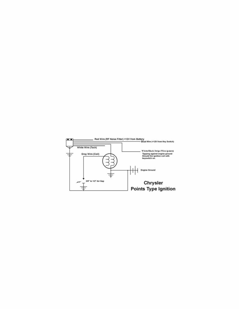
8 Chrysler Troubleshooting Points Type Ignitions with Amplifiers (Power packs) (Preamps are electronic replacements for points) A large proportion of the problems with the battery CD units are caused by low battery voltage or bad ground connections. Low voltage symptoms are weak fire or erratic firing of cylinders. Maintenance free batteries are NOT recommended for this application. WARNING!! Battery reversal will cause severe damage to the CD module and rectifier. NOTE: The Chrysler CD modules are similar to the OMC CD modules with the exception of wire colors. The chart below will assist you as a general guideline for the Chrysler units: Red +12V from battery (RF Noise Filter) Blue +12V from the Key Switch Gray + Terminal of ignition coil White OEM Tachometer signal White/Black Stripe Points or Preamp Module Black Engine ground No Fire at All: 1. Clean all battery connections and engine grounds. 2. Make sure the CD module is grounded. Units using rubber shock mounts require a ground wire fastened from the pack to the engine block. 3. Connect a spark gap tester to the high tension lead coming from the ignition coil and set it to approximately ½”. If it fires when you crank the engine over, there is a problem in the distributor cap, rotor button or spark plug wires. Wiring Connection for Testing CD Module NOTE: Preamps are an electronic version of points and the ignition module will test the same for both. 4. Check voltage present on the blue wire at cranking. It MUST be at least 9½ volts. If not, the problem is likely in the harness, key switch, starter or battery. 5. Connect a DC voltmeter to the white/black wire (while it is connected to the distributor) and rotate the engine. There should be some fluctuation in the meter reading. If the reading is high, and fails to move up and down, there is definitely a problem inside the distributor. If the reading is low, disconnect the white/black wire from the distributor and with the key switch turned on, strike the white/black wire against engine ground. The unit should fire each time. If it does, then the CD module is usually good and the points (or Preamp) require checking. If the CD module fails to fire with this test, then the CD module is usually bad. 6. Check DVA voltage on the gray wire going to the coil, it should be approximately 200 volts at cranking. If the voltage is correct, replace the coil with another coil and retest or use a load resister if another coil is not available. A coil that is shorted internally will give a low reading. In this case replace the coil and retry. After repairing the engine, check the battery voltage at approximately 3500 RPM, The MAXIMUM allowable voltage reading is 16 volts and the minimum is 12V. Running below 12V or over 16 volts will damage the ignition. Check for loose connections or a bad battery.
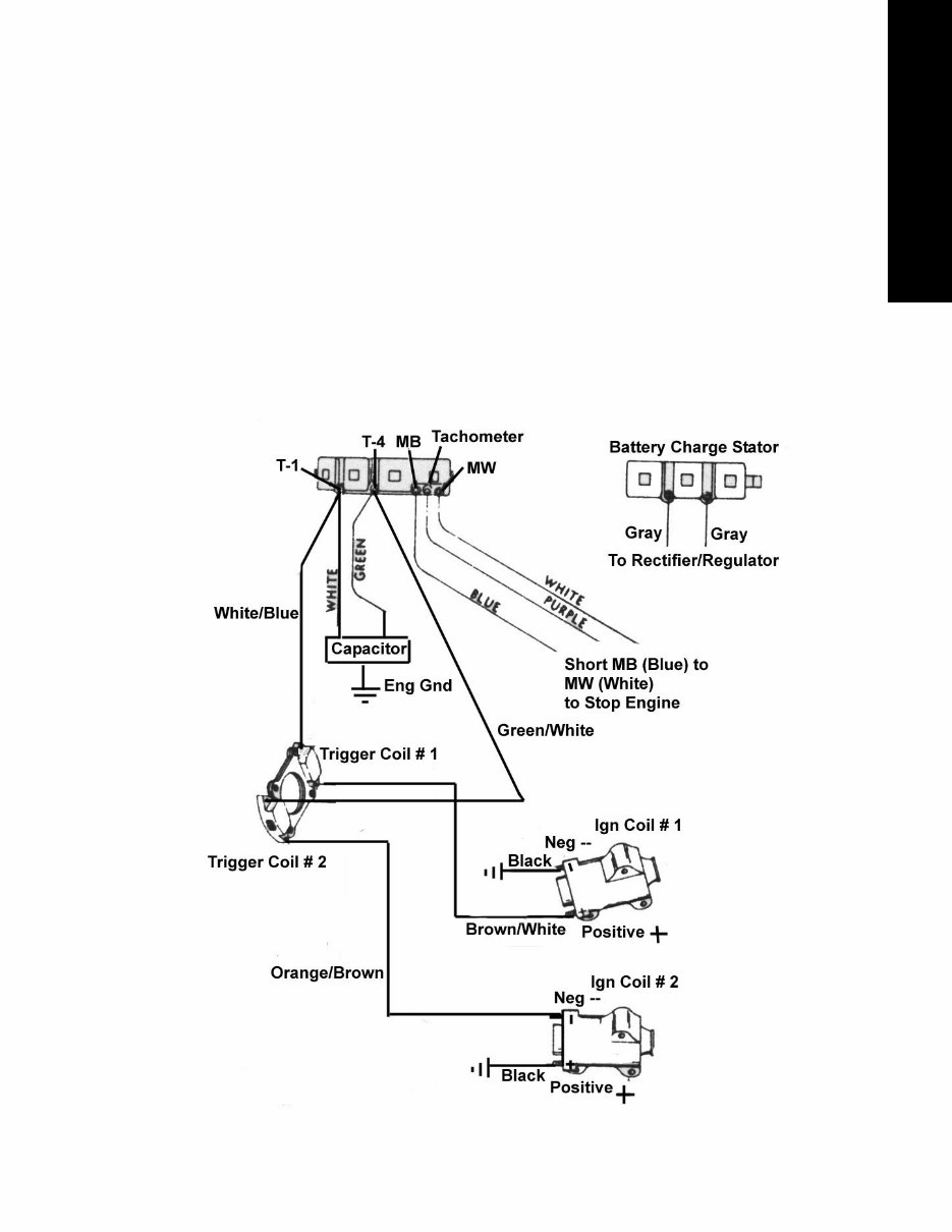
9 Chrysler/Force Troubleshooting Magnapower II Systems 1. Disconnect the white and blue kill wires from the CD Module and retest. If the engine starts and runs, the key-switch or kill circuit is bad. 2. Connect a DC voltmeter from the kill wires to engine ground and turn the ignition switch on and off several times. At no time should you see battery voltage on the kill circuit. 3. Connect a spark gap tester to all cylinders and test with the spark plugs in and out. If the coils will not fire with the spark plugs in, check compression with the spark plugs removed from all cylinders. A blown head gasket on these engines can prevent the coils from firing with the spark plugs installed. This is caused by a hard to explain problem with the triggering circuit. 4. Crank the engine with the starter and then stop. Check the DVA voltage on terminals T1 and T4. You should read between 170 and 270 volts Positive on terminal T1 and between 170, and 270 volts Negative on terminal T4. (Remember that some DVA adapters are not polarized and will read the same regardless of the polarity). If there is a low reading on one of the terminals, disconnect the white/blue and green/white trigger wires, then retest. If the readings are now correct, one of the trigger modules is bad. A continued low reading may be caused by a bad capacitor. To test, use a couple of jumper wires and swap the green and white capacitor wires going to terminals T1 and T4. If the low reading remains on the same terminal, the CD is bad. If it moves when you move the capacitor wires, the capacitor is shorted. 5. Check to see if the ignition coils are wired correctly. The #1 coil on a two cylinder engine and the #1 & 2 cylinder on a four cylinder engine are wired as NEGATIVE GROUND. The #2 coil on a two cylinder engine and the #3 & 4 cylinder on a four cylinder engine are wired as POSITIVE GROUND.
10 Chrysler Troubleshooting Capacitive Discharge Module with Alternator (ADI – Alternator Driven Ignition) General Troubleshooting 1. Disconnect the kill wires from the CD and connect a DC voltmeter between the kill wires and engine ground. Turn the ignition switch on and off several times. If, at any time, you see voltage appearing on the meter, there is a problem in the harness or ignition switch. At NO TIME SHOULD YOU SEE BATTERY VOLTAGE ON A KILL CIRCUIT. 2. Check the flywheel for a broken or loose magnet. 3. Check for broken wires and terminals, especially inside the plastic plug-in connectors. We recommend that you remove the pins from the connectors using the CDI 511-9706 pin removal tool and visually inspect them. 4. Visually inspect the stator for burned or discolored areas. If found, replace the stator. If the areas are on the battery charge windings, it indicates a possible problem with the rectifier. IF NO FIRE ON ANY CYLINDER: 1. Disconnect all kill wires AT THE PACK. 2. Check for broken or bare wires on the unit, stator and trigger. 3. Using the CDI meter with the 511-9773 peak reading adapter, or CD-77 and 511-9770 piercing probes, measure DVA voltage of the stator between the output wire sets. With everything connected, reading’s should be approximately 180 volts or more. Resistance readings between the stator wire sets range from 680 – 800 ohms (factory) and 400 – 500 (CDI/RAPAIR). 4. Disconnect the rectifier. If the engine fires, replace the rectifier. NO FIRE OR INTERMITTENT ON ONE CYLINDER: 1. Check the stator resistance, you should read 680-800 ohms (factory) and 250-350 ohms (CDI/RAPAIR) DVA 180V or more from blue to yellow (Note – On some two cylinder engines, the stator has two blue wires and no yellow wire. The stator will read from blue to blue). All stator wires should read open to engine ground. 2. Check the trigger resistance, trigger wire sets read approximately 50 ohms between the wire sets (DVA-5V or more), and open to engine ground. 3. If readings are good, disconnect kill wire from one pack. If the dead cylinder starts firing, the problem is likely the blocking diode in the opposite pack. NO FIRE ON TWO CYLINDERS: If two cylinders from the same CD unit will not fire, the problem is usually in the stator. Test per above. ENGINE WILL NOT KILL: Check kill circuit in the pack by using a jumper wire connected to the kill wire coming out of the pack and shorting it to ground. If this kills the pack, the kill circuit in the harness or on the boat is bad, possibly the ignition switch. COILS ONLY FIRE WITH THE SPARK PLUGS OUT: Check for dragging starter or low battery causing slow cranking speed. DVA test stator and trigger. HIGH SPEED MISS: 1. Using the CDI meter with the 511-9773 peak reading adapter, (or CD-77) and 511-9770 piercing probes, DVA check stator voltage to each pack at high speed. If it exceeds 400 volts, replace the pack. 2. Disconnect the rectifier. If the engine fires, replace the rectifier. Two Cylinder Engines with Combination CD Module with Built-in Ignition Coils NO FIRE OR INTERMITTENT ON ONE CYLINDER: 1. Check the stator resistance, you should read 680-800 ohms (factory) and 250-350 ohms (CDI/RAPAIR) DVA 180V or more from blue to yellow (Note – On some two cylinder engines, the stator has two blue wires and no yellow wire. The stator will read from blue to blue). All stator wires should read open to engine ground. 2. Check the trigger resistance, trigger wire sets read approximately 50 ohms between the wire sets (DVA-5V or more), and open to engine ground. 3. If readings are good, disconnect kill wire from one pack. If the dead cylinder starts firing, the problem is likely the blocking diode in the opposite pack. ENGINE WILL NOT SHUT OFF: Check kill circuit in the pack by using a jumper wire connected to the kill wire coming out of the pack and shorting it to ground. If this kills the pack, the kill circuit in the harness or on the boat is bad, the ignition switch could also be bad.
Chrysler/Force Troubleshooting 11 Chrysler/Force Troubleshooting Prestolite Capacitive Discharge Module with Alternator (ADI – Alternator Driven Ignition) Two Cylinder Engines Using a Separate Switch Box and Ignition Coils 1. Disconnect the stop wires from the CD and connect a DC voltmeter between the stop wires and engine ground, turn the ignition switch on and off several times. If, at any time, you see voltage appearing on the meter, there is a problem in the harness or ignition switch. At NO TIME SHOULD YOU SEE BATTERY VOLTAGE ON A STOP CIRCUIT. 2. Check the flywheel for a broken or loose magnet. 3. Check for broken wires and terminals, especially inside the plastic plug-in connectors. We recommend that you remove the pins from the connectors using the CDI 511-9706 pin removal tool and visually inspect them. 4. Visually inspect stator for burned or discolored areas. If found, replace the stator. If the areas are on the battery charge windings, it indicates a possible problem with the rectifier. IF NO FIRE ON EITHER CYLINDER: 1. Disconnect all stop wires AT THE PACK. 2. Check for broken or bare wires on the ignition module, stator and trigger. 3. Using the CDI meter with the 511-9773 peak reading adapter, or CD-77 and 511-9770 piercing probes, measure DVA voltage of the stator between the output wire sets. With everything connected, reading’s should be approximately 180 volts or more. Resistance readings between the stator wire sets ranges from 680 – 800 ohms (factory) and 250-350 ohms (CDI/RAPAIR). 4. Disconnect the rectifier. If the engine now has spark, replace the rectifier. NO SPARK OR INTERMITTENT ON ONE CYLINDER: 1. Check the stator resistance, you should read 680-800 ohms (factory) and 400 – 500 (CDI/RAPAIR) DVA 180V or more from blue to yellow (Note – On some two cylinder engines, the stator has two blue wires and no yellow wire. The stator will read from blue to blue). All stator wires should read open to engine ground. 2. Check the trigger resistance, trigger wire sets read approximately 50 ohms between the wire sets (DVA-5V or more), and open to engine ground. 3. If readings are good, disconnect stop wire from one pack. If the dead cylinder starts sparking, the problem is likely the blocking diode in the opposite pack. ENGINE WILL NOT STOP: Check the stop circuit in the pack by using a jumper wire connected to the white stop wire coming out of the pack and shorting it to the white stop wire coming out of the other pack. If this stops all spark from the pack, the stop circuit in the engine harness or on the boat is bad, the ignition switch could also be bad. COILS ONLY HAS SPARK WITH THE SPARK PLUGS OUT: Check for dragging starter or low battery causing slow cranking speed. DVA test stator and trigger. HIGH SPEED MISS: 1. Using the CDI meter with the 511-9773 peak reading adapter, (or CD-77) and 511-9770 piercing probes, DVA check stator voltage to each pack at high speed. If it exceeds 400 volts, replace the pack. 2. Disconnect the rectifier. If the engine now has spark, replace the rectifier. Three and Four Cylinder Engines Using Separate Switch Boxes and Ignition Coils 1. Check for broken wires and terminals, especially inside the plastic plug-in connectors. We recommend that you remove the pins from the connectors using the CDI 511-9706 pin removal tool and visually inspect them. 2. Check the flywheel for a broken or loose magnet. 3. Disconnect the stop wires from the CD and connect a DC voltmeter between the stop wires and engine ground, turn the ignition switch on and off several times. If, at any time, you see voltage appearing on the meter, there is a problem in the harness or ignition switch. At NO TIME SHOULD YOU SEE BATTERY VOLTAGE ON A STOP CIRCUIT. 4. Visually inspect stator for burned or discolored areas. If found, replace the stator. If the areas are on the battery charge windings, it indicates a possible problem with the rectifier. IF NO SPARK ON ANY CYLINDER: 1. Disconnect stop wire AT THE PACK. 2. Check for broken or bare wires on the unit, stator and trigger. 3. Using the CDI meter with the 511-9773 peak reading adapter, or CD-77 and 511-9770 piercing probes, measure DVA voltage of the stator between the output wire sets. With everything connected, reading s should be approximately 180 volts or more. Resistance readings between the stator wire sets range from 680 – 800 ohms (factory) and 250-350 ohms (CDI/RAPAIR). 4. Disconnect the rectifier. If the engine has spark, replace the rectifier.
This is the COMPLETE Official Service Repair Manual for the CHRYSLER FORCE OUTBOARD MOTORS. Production model years 1964 to 1999. It Covers complete tear down and rebuild, pictures and part diagrams, torque specs, maintenance, troubleshooting, etc. You name it and its in here.
Models Covered:
Chrysler Marine 3.5-140 HP & 3/8-16 bolts 5/16-18 bolt
CD Also Cover Force Outboard Engines
Force Outboard Service Manual
1984-1999 Force 4.-125 HP Outboard
This Manual contains everything you will need to repair, maintain, rebuild, refurbish or restore your CHRYSLER OUTBOARD. All diagnostic and repair procedures are covered. The manual has detailed illustrations, diagrams, wiring schematics and specifications as well as step-by-step instructions. All pages are printable, so run off what you need and take it with you into the garage or workshop. These manuals are your number one source for repair and service information. They are specifically written for the do-it-yourselfer as well as the experienced mechanic. Using this repair manual is an inexpensive way to keep your CHRYSLER OUTBOARD working properly. Each manual provides step-by-step instructions based on the complete disassembly of the machine. It is this level of detail, along with hundreds of photos and illustrations, that guide the reader through each service and repair procedure.
SERVICE REPAIR MANUAL COVERS:
Chrysler Outboard Schematics Wiring
Tools & Techniques / Fuel System
Ignition and Electrical Systems
Power Head / Gear case
Automatic Rewind Starter
Power Trip & Tilt
Remote Control Systems And Index
General Information and index
Frame, Body Panels, Exhaust system
Maintenance- tune-ups, cables & more
Engine Removal and Installation
Lubrication System Cooling System
Lubrication Maintenance & Tune up
Engine Synchronization and Linkage Adjustments
Sub-Transmission and Gearshift Linkage
Crankcase, crankshaft, Balancer
Electric starter, Ignition System
Battery and Charging System
Lights, Meters, Switches
Transmission System &Wiring
Troubleshooting & Tips
Technical Miscellaneous & More
Files Scanned
Chrysler Outboard Schematics Wiring
Service Fundamentals Periodic Servicing
Chrysler Outboard Troubleshooting
Model Specification: Chrysler Force Outboard Motors
Model Year: 1964-1999
Language: English
File Format: .PDF or .OVA
Total Pages: more than 3000 pages
Requirements: Adobe Reader & Win
ZOOM IN/OUT: YES
INSTANT DELIVERY: YES
Specifications: FULLY PRINTABLE & BOOKMARKED
Compatible: All Versions of Windows & Mac
This QUALITY manual is 100 percents COMPLETE and INTACT, no MISSING/CORRUPT pages/sections to freak you out!
This file is Bookmarked and SEARCHABLE to make what you need easy to find.
Detailed illustrations, exploded diagrams, drawings and photos guide you through every service repair procedure.
This manual can be viewed on any computer, as well as zoomed and printed.
Complete comes in format which can work under all PC based Windows operating system and Mac also. It saves to your hard-drive and can be burned to CD-ROM.
INSTANT MEANS THERE WILL BE NO SHIPPING COSTS OR WAITING FOR A PAPER OR CD MANUAL TO ARRIVE IN THE MAIL. YOU WILL RECEIVE THIS MANUAL TODAY VIA INSTANT DELIVERY ON COMPLETION OF PAYMENT VIA OUR SECURE PAYMENT PROCESSOR.
WE ACCEPT ALL MAJOR CREDIT/DEBIT CARDS AND PAYPAL.
YOU CAN DO THE REPAIRS YOURSELF AND SAVE MONEY $$
Recently Viewed
5,521,897Happy Clients
2,594,462eManuals
1,120,453Trusted Sellers
15Years in Business
Price:
Actual Price:
1964-1999 Force Outboard Motors OEM Service & Repair Manual

 - !")