

West Bend Elgin outboard motor service repair manual
What's Included?
Fast Download Speeds
Online & Offline Access
Access PDF Contents & Bookmarks
Full Search Facility
Print one or all pages of your manual

West Bend Service Manual 1956 -1960
Thanks for doing business with us. We are a private concern focusing on restoring
old tired iron to sleek running condition. You can visit us on the Internet at:
This West Bend service manual on CD contains more than 150 pages. It is
searchable by keyword and it covers these topics, in 10 sections, applicable to all
models manufactured between 1956 and 1960:
• Section A – Engine Cover
• Section B – Starter, Rewind
• Section C – Magneto
• Section D – Carburetor, Fuel System
• Section E – Power Head
• Section F – Lower Units
• Section G – Controls
• Section H – Standard Adjustments
• Section I – Tools
• Section J – 80 hp Service Manual
7
.-
( r
I
WEST BEND
OUTBOARD MOTOR
SERVICE MANUAL
(r
(r
qp
r sta
r
(r,
(
#,t
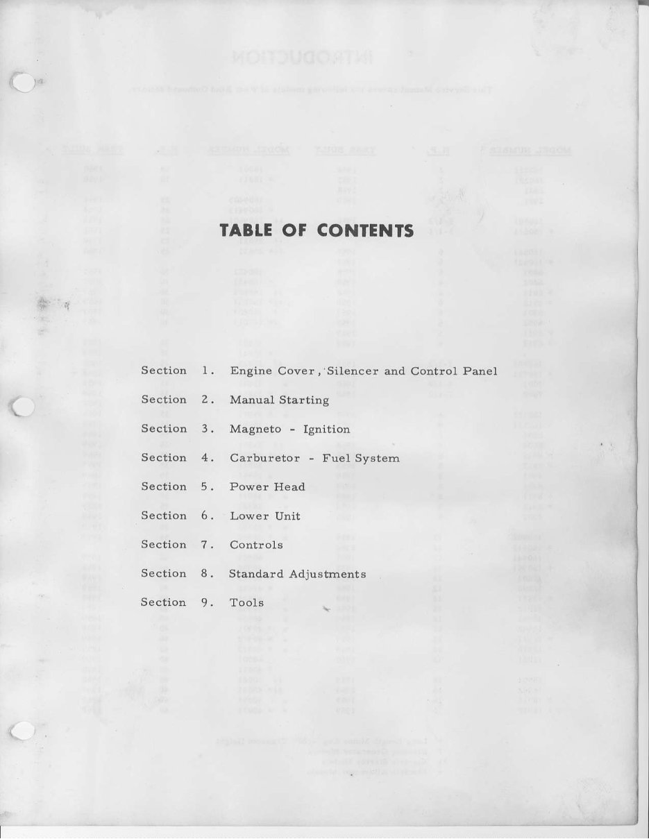
TABTE OF CONTENTS
Engine Covox,'Silencer and
Manual Starting
Magneto
-
Ignition
Carbuf,eto"
-
Fuel System
Powor Heatl
Lower Unlt
Controls
Standa!d Adjustment6
Tools
Section l.
Section 2.
Section 3.
Sectlon 4.
Section 5.
Sectiolr 6.
Section 7.
Section 8.
Section 9,
t
Cont!ol
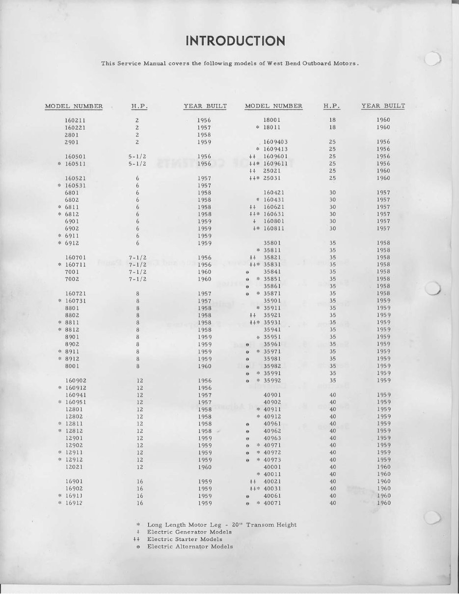
INTRODUCTION
This Selvice Mdual covels the followir{ hoders ol West Bend Outboald Motors,
MODE! NUMBER
I
!E
2
2
2
z
5-rtz
5-L/2
6
6
6
1-vz
7-|Z
7-UZ
I
8
I
I
8
I
8
8
3
a
8
tz
tz
t2
l2
\2
\z
).2
).2
tz
t2
\z
t2
'12
l6
16
16
l6
YEAR BUIJ]T MODEL NUMBER lI.P. YEAR BUIIT
l602l l
L6022L
2a0I
290 L
16050I
* I605Il
16052I
* 160531
6801
6302
n 6812
6902
4 6912
160?0t
* l60?ll
?00I
1002
t60721
* 160?3I
8801
8802
* 88t I
* a8t2
390t
a9az
+ a9tl
+ s9t2
8001
160902
160941
* 16095 r
I2a0l
tzao2
+ I23lI
+ rzatz
I2901
LZ90Z
*
tz9ll
4 L29tZ
12021
16901
16902
+ l69rl
+ r6912
r95?
r953
r959
1956
r95?
I95A
r958
r958
1958
t959
1949
),949
r956
r9a6
1960
1960
1967
1957
1958
1958
1958
1958
1959
195 9
r959
!959
I950
L9a6
I966
t9a7
I958
1958
1958
1958
1959
r959
r959
r959
1960
1959
r959
1959
1959
13001
* 180 rl
,1609403
* 1609413
tt 25021
r1* 25031
160421
* 160431
+t 160621
+l+ t6063r
a r608ol
t* t603t I
35801
* 3581I
t+ 35821
t+* 3583r
6
*
3585r
3590I
* 3591I
++ 35921
t+* 3593r
3694L
* 3595I
. 35961
. 3598I
6 34932
.
*
35992
40001
+l 40021
ta
z5
30
30
30
30
30
30
r960
r960
1956
r956
rjt6
I960
r960
t9a7
L9a7
r958
r958
1958
I958
1958
r953
r958
1959
1959
1959
1949
r959
1959
t959
195 9
I959
1959
195 9
r95 9
r959
t959
1960
1960
1960
35
35
35
,a
35
35
3a
l5
35
35
35
35
40
rlo
40
40
40
4t)
4
40
)
+
Long Lencth Moto! I,ea - 20" Tra8om Height
I Electic Cen€rator Models
+l Electric Siaiter M6de1o
6 Electric Altelnato! Models
I
I
SECT|ON 1
ENGINE COVER
CARBURETOR AIR SILENCER
AND CONTROL PANEL
(
I
SECTION I
ENGINE COVER
The eDsine.ov€r is ma,le ol pigmenre.lPol)e"re, re'in
imDresirreLl wirh elas\
hbrei 16r srrenqth. lr is 504
lighteithan aluminim, hds2'> time' rhe impa(t s(rengrlr
of steel and is sound absorbent.
On motors built prior ro llr58, rhe eneine (over ij sc
.ured b) a latch and bail lo(.rted cr llre rear ol the
iupport plate.
NOTE: lf dimcully is experienced when replacing th€
cov€r, loos€n the tivo scr6ws which attach the control
panel
to the suppor! plate. Move,on(rol pan€l torwatrl
irn(il (over firs-dropeily, rhen tightcn screwr.
on motors built after 1957, the cover latch assemblies
are contained on the control panel. Only the cov€r
la!,h sprinq,
(over latch rprinq 'erainer, hex
iim
nuts
and k;obs'(ser page 2 ol paris ind in"tru,(i;n bookl
are replaceabl€ sepaiaiely.
FLYWHEEL STRIKING ENGINE COVER
A few cas€s have been reported of the llywheel strikillg
lhe inride ot rhe erreine iorer Lturins opcrrlion ol rl,;
motor. Check thc ul,per eilge of ihe lliwhe€l rnd dre
inside of rl)e
(over
lor eridence of rubbing. To
(orr€.t
ftis conJition, rdju\t lhe positionol thi power heaJ
in relatjon to th€ support platc rs tollowsl
5.t/2 THROUGH 8 H.P. MODCLS
L R€move engine cover. Press ff)wheel towzrJ the r€ar
of the supportplarc and rclease .rllowingmotof to return
to rts normar posl$on.
2. Open carburetor a(cess door and note the relation-
ship b€lwe€n rh€
(enter
linc o[ the ac(ess .loor opening
and the hish spcedand nlle nee(lleiof tbe
(irrbirrctor:
The high spced an(l idl€ needlcs sl,oul,l be rpproximJte.
ly l.8"-to ihe l€(r ol the center line, tacingihe motor
If the carbureror needlei are toward the right side oi
cent€r,do the followioS:
A. l,oosen rh€ two so(l€r hea.t r ap x rews whn h cl.rm1,
thc rupport plate io rhr king pin.
B. Facingthe motor from the Iiont, rotate fic support
plate counter-clockwise until the carburetor ecdlcs
lre l/8" m the left of (hc ce ter line as described
C. Tighten the two ciamping screws securely. This
will center the magnetoflywheeland prevent it from
striking the cover.
NOTE: The rop o{ rhe kinB
l,i'r
rhoul.l be llusltwi'lr
ihe top of the support plrte.
12 H.P. MODEIS
1. Removeengine cover.
2. Loosen the two socket head cap soews which clamp
the support plate to the king pin.
3. Facins the motor irom dre front, rotate the support
' plate cointer-clockwisc until the neasurement beiween
ihe sideof the cylinder head ard the outside of the sup
pofl pla(c i5 2-5 16" 'o 2-l l'on tr,e pofl. o. sree.inS
handle side, and 2-1116"to 2" on the starboardside.
Measure at a point just above the cylinder head gasket.
4-
'l
ighten dre rwo clamping s.rcws securely.
\Ollr: The rot, uf (he kins pin d,oul,l l,e flush witlr
rhe ropotrhe\ui'Dorr
plar".'Tiri',.lrustment
qill,enter
rlre Hiwheel ,*i pre'i't ir lroL sriiking rhe.o\er.
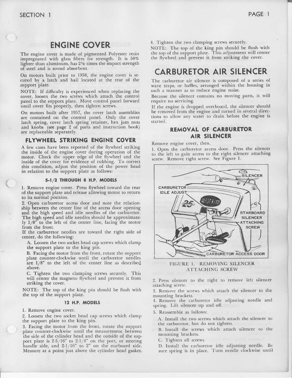
CARBURETOR AIR SILENCER
"lh€
carbur€lor an silcncer is composed ol a series of
wave traps, or bam€s, arranged.wiahin the housing iD
such a manner as to r€duc€ engtne nore
Be.ause the sileD.er contains no moving parts, it will
requir€ no serv'cing.
ll rhc eusine i',lropl)e,l ,^t't1,,'Jt,l.lhe silen(er should
l* n ,rrori,l lr urrr thi ingi,re rn,l I L,I ne,l in 'e\ errl direr'
tions to rllo$'any watei to
(lraiit befor€ the engine is
R,EMOVAL OF CARBURETOR,
AIR SILENCER
Renmve engiDc
(,ver,
therr,
L Oxer rhe (.rrbt'r,t,r r,.e*
(lnor. Pre'r 'he silen(er
r,, rhielett r" gaiu rc,e* r" re riglrt lilerr(er itta.hing
screw. Remove right soew. See FiSure l.
CAFBUFETOR
STARBOARO
SILENCER
ATTACHING
PAGE I
nrountiug brackets.
.1.
Rc rovc the .arburetof idle
spring. Lift silencer up rDd oli.
5. ReNsemble as followsl
,4.. Install rhe two screws$4ti.h attach the silencer to
rhe carbur€tor, but do not tighten.
B- lnstall the s.rews whi.h rttach silencer to the
mountinS brrckets.
C. TighteD all screws.
D. Install the carburetor idie adjusting needle. Bc
sure spring is in place. Turn needle clockreise Lrntil
rlGUR]' 1, RIiI'OVING SILtrNCER
A'ITACHINC SCREW
2. Prcss silencer !o the right t,r remove lelt sil€ncer
3. Rem.rvc the s.r€ws which attach the sileDc€r to the
adjusting nc€dle and
)

I
PAGE2
sEcTtoN 1
closed. Do Do lor.e.
-rurn
needie .ounter clockwise
3,4 turn. This is the averagc idle ne€dleadjusrment.
R.EPLACEMENT SILENCER
.lhe
sef!ne rcplacemcD! rir silencer, part No. A108205,
can be use.l r)n all25,30 an,l 35 H.P. models, builr prior
to 1959. rhe sil€ncer is furnished with a toam?iasric
plug installed in rhe srarbo?rd ]e€ of rhe silencel..
Renbve this pllg b€fore installir)g silencer on 35 FLP.
llr 'Jre rl,i,
t,l,,e
i, iI
I,1.,,.
l,ct,reiLrr.l:ng si., n,er orr
z5 rD.l :i(,H.P.;',"lel\
NO']1-: The crrburer(,. rill,ilencer. was
(LiscoDdnued
in 1951)
on all nro{lels-16rhrough 40 H.P.
CONTROL PANEL
'IIIc
control
l)r'rel
cofrcsl)on(ls r{) rhc
(lashborfd
ol a .ar.
ll,, , {rn'1, I,r rh.,h,,te 'r:,rt,r.U,,1 gerr ' h i r r ,re
l,r.rlr,l lrp'c l,,r .,,I\' ip're. T,, \1 t i, e rlreI :rrLurcr,,r,
rcc,l
lrhre.,r
r,, r,
t,1.,,e
r ,r.,rter r,,tx. ir i. n,,r ne,c- v
rf, rernir\e rjrr,r{Lrot
l)rnet.
TO REMOVE CONTROL PANEL
MANUAI START MOTORS
L Renn,ve crginc .ovcr.
2. l)isconDe(trhc (hoke
rod lfor)r thc carburebr.
NO'Ilr: I hp l,,ll,,\iDJ.i {rrl,
is ni,r rppli,.,ble ro nroror,
Inrilr i'r Il'18 ,{ .,lr(r. Ori rbe\e rniL6rr. rhe ge. shitr
ro,l "t't'cr n rer.ri'rc,l iI rhe c,'nrr(n puel Ly l (olpler
rh.rr
wiil .rll,tr{ rh( s(,,r .hilr r,rl rn tliseng:rge when rhe
1 RerF,,vc ,,,||(r
1,irr
,rrr,l ,lir,,rrDerr Lhe g(Jr rhrlr r,\1,
!'llrer, lr.rn rl,( ,r,,rk.r\. Iros. ll rhe ,olrrol
r)anel
js
to be rcplxce(I, it i$ Dccess|rl to sepnrale rhe gCar shitr
,onrrol iu,l tr,,rrr rhc gc:rr.lritr teveirrm by driviDs our
rhe grnnv. pi . sli,h will i,l1.w LheroDrrol rorl ro par'
lirrougn tne p.rDer.
NOTL: On earlier producrion moclels, the gear shi{t
knob was artachcit !o ihr: gear shilt control rod'by rneans
of a gfoove pin, which iirn bc driven out ro permit
r€moval of the kDob.
4. Re tove strrter rop€ hnrdlc, unrie kDor xod allow
fopc to fcwhd oD the spool.
5. Rcnrove the s.rews w|i.h rtt..h rhe conrrol paDel ro
6. Rcmove prDel lrrr support plale.
EIECTRIC START MOTOTS
L PF'lo'nr ,rel^
-.
.:. 3 .,!,1 6 li'te.l above.
2. Renbve el.(triel .onpon.nts from the control panel.
Do not
(liscorne(r
thc wir.s trom lhe coml)oneDrsas rhis
rvill sale rime rn(t nlyr
l,revenr
improper hook-up during
3. Rernove prnel from support ptate.
REASSEMBLY OF CONTROL PANEL
r,lANUAl, START I OTORS
l. \*ernLle .nIUul
;,.rrrel
ro rhe supporL pli(e. Srarl
r|r.'.l,ing n'Fw. irur ,]a noL rishren.Orr 1958 rlrrough
l:,rI r"r^,. rl,,r 1,.,!e .,n .,rengine gexrshilr.insrall tEe
I'n,r
:,|I 'l,ing ",'s [,,r. rhen
pnsdge
rhe "Dil of the
e e ' r J , i l r ,,.1 !tirl,rhe,^,rtn,n8 in rhe,orrrrol panel.
lr',r:,.1 url,,1
tL,r"l
-r.!hirg nr.$r i,nLlrighren. For
rne5r rnurors clrsregrr,r srel z.
l.
(.uI|,rr
q,,, J,il dl. uprrer. ro rhe
s'.rr \hilt leter
:'rm: r. irr.r.'ll gerr Jrr.r kirob lunille ind drive in
gtoovc pin,
(lepending
on the method of disassembly
3. Connect choke rod to carburetor.
4. l\rll nrrrt€r rope thfough the conrrol panel and insralt
tlre strrt€r' ropc han(lle and plug. Establish initial ten-
sioD or the stlrtcr. rcwin(l spring as described in rhe
5. lnstall the cirburer(n rir silenccr,if previously r€-
6. hstall the cafburetor idlc adjustmenr Deedle and
sP n8.
N()|l : Il,c nrcd
r,,,le\
ir rhe \ut,t)orL phLe are elon-
c.,rc.l .,lti,,xinlrcl' | 8 r"
t,erniii lroper
alignment
"r rnc
l):rncr
rr"r
(^vcr.
EICCTRIC START MOTOTS
l. PefliDnt stcps l, 2, irnd 3 liste(l above.
2. Instrll elect|i(rl coD)poDents to the control panel
'ruking sLrfcto pl,r(:c the alectrical wircs in their originai
3. PefldI]l stcl)s 5 rr(l l; listed above.
--F
\.'r
C
sEcTtoN 2
STARTER. . . AUTOMATICREWIND
I
SECTION 2 PAGE]
Slorter
/
a
lT6-
-o
t
'So
lD
6
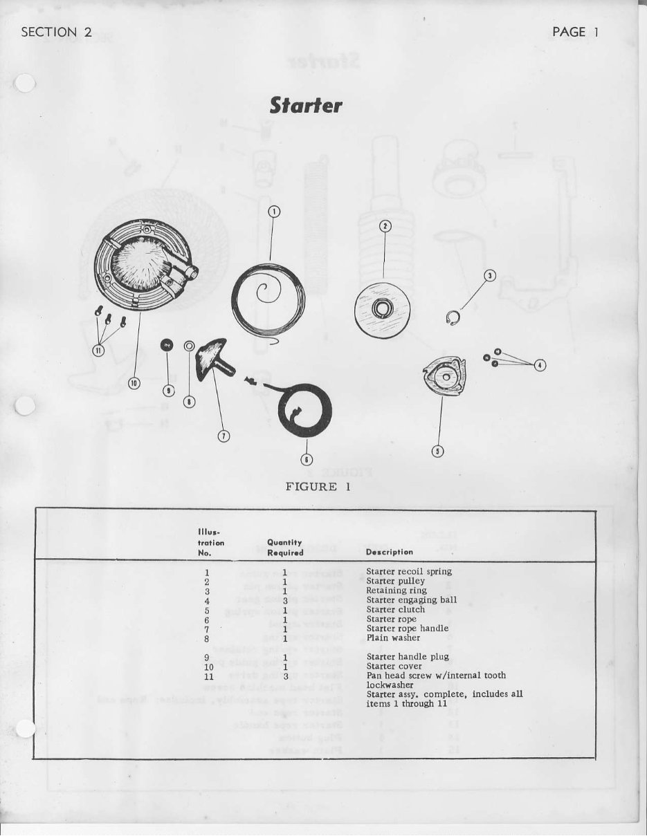
FIGURE I
9
10
11
Starter recoll spring
Starrer
Dulley
R€t.lnlng ling
Starterengaging bau
slaner handle plus
Pan h€ad3crew $/internal both
staner.ssy. complete. hcludes all
ilems I through11
I
t
I
PAGE 2
sEcTtoN 2
2
I
I
Y-"
f--',
.t
I
PJ
o
@
ry
I
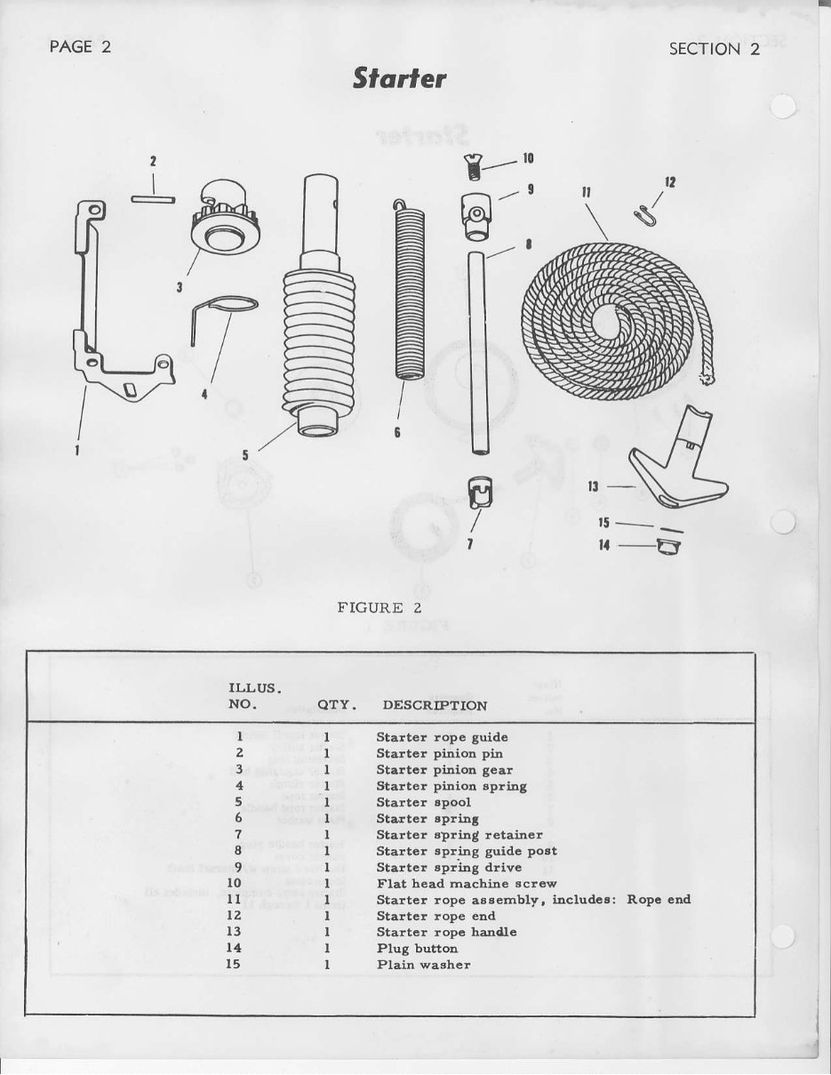
SIarIer
FIGURE 2
I
F
I
E-
t5-_
||-B
ILLUS.
NO. QTY. DESCRIPTION
I
z
4
5
7
I
9
lo
lt
t2
l3
t4
l5
I Starter ropc guide
I Stattc! pinior pil1
I Staltc! pittloE geat
I Start€r pinion spling
I Starte! spoo]
I Sta.lt€t tpliD!
I Starter spriDg retabcr
I Starter 8plitlg guidc post
I Starter spridg dliv6
I Flat head machiae scresl
I Startcr rope assernbly, includes: Ropc cDal
I Startor rope eld
I Startcr ropc ha l1e
I PluB button
I Plain x,a3hc!
You're Reading a Preview
What's Included?
Fast Download Speeds
Online & Offline Access
Access PDF Contents & Bookmarks
Full Search Facility
Print one or all pages of your manual
$31.99
$41.99
Viewed 83 Times Today


Secure transaction
What's Included?
Fast Download Speeds
Online & Offline Access
Access PDF Contents & Bookmarks
Full Search Facility
Print one or all pages of your manual
$31.99
$41.99
If you're in need of a comprehensive service and repair manual for West Bend Elgin outboard motors manufactured between 1956 and 1960, this factory manual is an invaluable resource. With 169 pages of detailed instructions, diagrams, and specifications, it covers the maintenance and repair procedures for 2 to 40 HP motors.
Whether you're a professional mechanic or a DIY enthusiast, this manual provides the essential information required to keep these outboard motors in optimal condition.


