

Raymarine E-Series Classic E80 & E120 Service Manual
What's Included?
Fast Download Speeds
Online & Offline Access
Access PDF Contents & Bookmarks
Full Search Facility
Print one or all pages of your manual
E-Series Displays - Service Manual
Contents
Important Information ................................................................................................................................ Page 3
Safety notices ........................................................................................................................................................ 3
Dismantling and reassembly instructions ......................................................................................................... 5
Exploded views ...................................................................................................................................................... 9
Plan of flexis and connectors ............................................................................................................................ 11
Parts list ................................................................................................................................................................ 13
System diagnostics ............................................................................................................................................. 15
PCB and Circuit diagrams ................................................................................................................................... 19
Trademarks and registered trademarks
Autohelm, HSB, Pathfinder, RayTech, RayTalk, RayTech RNS, Sail Pilot, SeaTalk and Sportpilot are registered trademarks of
Raymarine Limited.Apelco is a registered trademark of Raymarine Holdings Limited (Registered in all major marketing territories).
AST, Autoadapt, Auto GST, Autoseastate, Autotrim, Bidata, HDFI, Marine Intelligence, Maxiview, On Board, Raychart, Raynav,
Raypilot, Raystar, ST40, ST60, Seaclutter, Smart Route, Tridata and Waypoint Navigation are trademarks of Raymarine Limited.
C-MAP and C-MAP NT+ are registered trademarks of C-MAP SRL. Navionics is a registered trademark of Navionics Company, Italy.
All other product names mentioned are trademarks or registered trademarks (if applicable) of their respective companies.
www.raymarine.com
© Raymarine 2005
RANGE
CANCEL OK
PAGE
ACTIVE
WPTS/
MOB
MENU
DATA
IN
OUT
E
E -Series Networked
Display (E80 & E120)
Service Manual
Document Number: 83177_1
Date: May 2005
Page 3 E-Series Displays - Service Manual
Important Information
Introduction
This service manual contains information to enable you to service the Raymarine E-Series Networked Display and
covers the E80 and E120 models.
Circuit diagrams contained in his document are typical, but may be subject to revision. If you have any queries relating
to the version required for a particular E-Series Display, please contact the Raymarine Service Department.
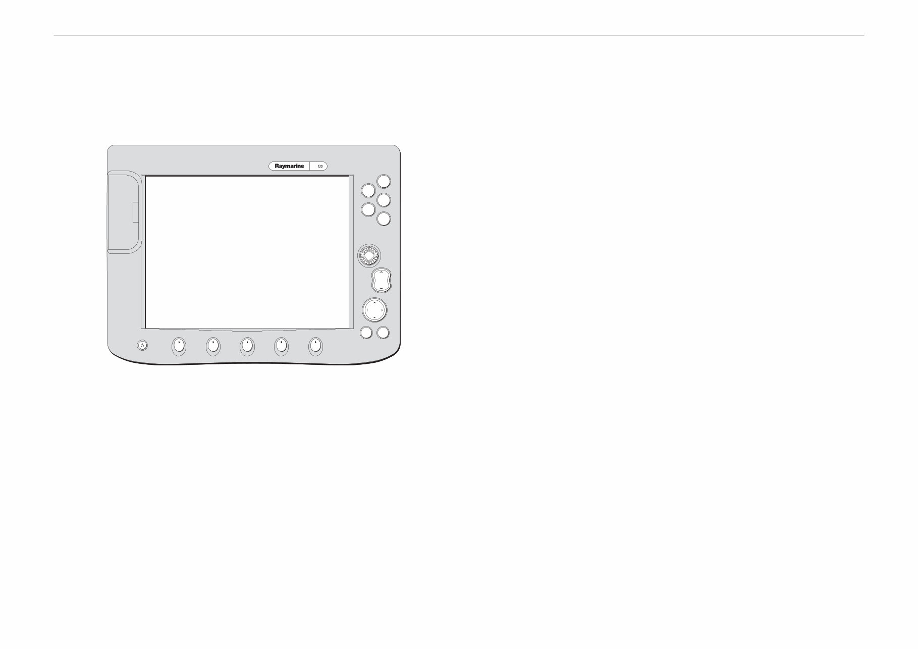
Product description
The E-Series Networked Displays are fully customisable units giving radar, chart plotting, fishfinder, video and
instrumentation functions using a high-brilliance sunlight viewable screen.
CE marking of equipment/replacement parts
If the Raymarine equipment under repair, test, calibration, installation or setting to work carries the European CE
mark, only parts and components supplied or approved for such use by Raymarine should be used in order to
maintain compliance with the relevant CE requirements.
Incorporation, use or attachment, by any means, of parts or components not supplied or not approved for such use by
Raymarine or, if supplied or approved for use by Raymarine, not properly fitted in accordance with instructions
published, provided or recommended by Raymarine, may cause the equipment to malfunction and in particular, to
become unsafe or to no longer meet the relevant CE requirements. In these circumstances, Raymarine excludes
liability to the fullest extent permissible in law for any loss or damage including any liability for its contribution to such
loss or damage by its negligent acts or omissions.
EMC conformance
All Raymarine equipment and accessories are designed to the best industry standards for use in the recreational
marine environment.
The design and manufacture of Raymarine equipment and accessories conform to the appropriate Electromagnetic
Compatibility (EMC) standards, but correct installation is required to ensure that performance is not compromised.
Technical accuracy
The technical information contained within this Service Manual, to the best of our knowledge, was correct at the time
of writing. However, Raymarine cannot accept liability for any inaccuracies or omissions it may contain.
In addition Raymarine’s policy of continuous product improvement may change specifications without notice. As a
result Raymarine cannot accept any liability for any differences between the product and the manual.
Safety notices
WARNING: Electrical safety
The E-Series Display contains high voltage. Ensure the power supply is switched off before
making any electrical connections.
WARNING: Product servicing
The E-Series Display must be serviced in accordance with the Raymarine instructions provided.
Failure to do so could result in poor product performance, personal injury, and/or damage to
the boat.
WARNING: Electromagnetic energy
The radar scanner transmits electromagnetic energy. Ensure that the scanner has been
installed in accordance with the recommendations given in the relevant scanner handbook.
WARNING: Fishfinder sounder module
Removing the transducer cable from the rear of the fishfinder sounder module whilst it is
switched on can cause sparks. Only remove the transducer cable after power has been
switched off. Ensure that the sounder module is mounted where it is well ventilated and in an
area free from flammable vapors.
CAUTION: Electrostatic discharge
The E-Series Display contains electrostatic sensitive components. Always observe the
appropriate precautions when handling, shipping and storing this product. Failure to do so
could result in permanent damage to the equipment.
CAUTION: CompactFlash cards
Removing the CompactFlash card while information is being written to, or read from, may
cause damage to the card and loss of all data. A warning on the display indicates when the card
is being accessed.
CAUTION: Card damage
DO NOT use a metallic instrument such as a screwdriver or pliers to help you remove a card, as
doing so can cause irreparable damage.
CAUTION: Water ingress
To avoid the risk of water ingress, DO NOT re-use seals once they have been disturbed. Ensure
that the blanking plugs are fitted into the rear of the Display, whenever the SeaTalk
hs
,Video In,
or VGA Out cables are disconnected.
CAUTION: Front plate
The front plate is ionised to protect it from corrosion. Care should be taken not to damage this
plate.
CAUTION: LCD display
The LCD should be suitably covered during service to prevent contamination from dust and
finger prints.

Page 5 E-Series Displays - Service Manual
Dismantling and reassembly instructions
Safety notices
CAUTION: Water ingress
To avoid the risk of water ingress,
• DO NOT re-use seals once they have been disturbed.
• Always fit the blanking plugs when the SeaTalk
hs
, Video in and VGA out cables are discon-
nected.
CAUTION: Front plate
The front plate is anodised to protect it from corrosion. Care should be taken not to damage this
plate.
CAUTION: LCD display
The LCD should be suitably covered during service to prevent contamination from dust and finger
prints.
CAUTION: Printed circuit boards
The appropriate anti-static precautions should be taken to avoid damage to PCB’s.
Introduction
This section gives step-by-step details for dismantling and reassembling both E80 and E120 displays. Before starting
work on a E-Series display attention should be given to the safety notices at the start of this section.
The numbers in brackets correspond with the item numbers shown in the Exploded Views on pages 9 and 10 of this
manual.
Tools required
To dismantle and reassemble an E-Series display, you will require the following tools:
• Suitable non-metallic wedge shaped tool.
• Pozi screwdriver.
• Flat-blade screwdriver.
To remove an E80 or E120
This section describes how to remove an E80 or E120 display from its mounting.
Flush mounted
1. Disconnect the power source to the display.
2. Remove the nuts (38) and the washers (36 & 37) from the rear of the unit.
3. Ease the unit away from the bulkhead and unplug all the cables, ensuring that you fit the blanking plugs (49 & 50)
in place of the SeaTalk
HS
cable and Video in/VGA out cables.
4. Unclip the bezel (2).
5. Dispose of the flush mount seal (41).
You are now ready to dismantle the E80 (see page 6) or E120 (see page 7).
Trunnion mounted
1. Disconnect the power source to the display.
2. Unplug all the cables from the rear of the unit, ensuring that you fit the blanking plug (49 & 50) in place of the
SeaTalk
HS
cable and Video in/VGA out cables.
3. Unscrew the trunnion knobs (43) and remove the unit from the trunnion brackets (44).
4. Unclip the bezel (2).
You are now ready to dismantle the E80 (see page 6) or E120 (see page 7).

Page 6 E-Series Displays - Service Manual
To dismantle an E80 Display
With the unit free from its mounting and the bezel removed (see page 5):
1. Without scratching the front plate (4), remove the 17 countersunk screws (3). Retain the screws for later use.
2. Carefully remove the front plate (4).
3. Remove and discard the window seal (5).
4. Remove the lower keymat (7). There is no need to remove the rotary control knob (8) or the side keymat (9) unless
they are damaged.
5. Using a suitable tool, carefully lift the black securing tab and disconnect the keyboard flexi (11) from the keyboard
PCB (12). See the diagram below:
6. Disengage the 2 clips securing the keyboard PCB (12) and remove it.
7. Holding the window (6) around the edges, carefully remove it from the unit. Care should be taken to protect both
the window (6) and the exposed LCD (15) from accidental damage or dust contamination.
8. Undo the 4 screws (14) holding the light box assembly (18) in position and retain for later use.
9. Remove the rear cover (39) and discard the connector panel seal (40).
10. Taking care to protect the LCD (15), lay the unit face down.
11. Using a suitable tool, carefully lift the securing tabs and release the CPU to CCFL flexis x 2 (30).
12. Unscrew and remove the high voltage shield (34).
13. Remove the HV cable assembly (19) and the fan connector (33).
14. Remove the 3 screws from the CCFL PCB (32) and retain for later use.
15. Lift the CCFL PCB (32) clear.
16. Carefully unclip the chartreader flexi (28) from the chartreader (13).
17. Gently free the chartreader securing clip and remove the chartreader (13).
18. Using a suitable tool, carefully lift the black securing tab on the LCD to CPU flexi (16) and temperature sensor flexi
(24).
19. Remove the 8 screws from the CPU PCB (29) and retain for later use.
20. Lift the CPU PCB (29) clear of the heatsink plate (25).
21. Using a suitable tool, carefully lift the black securing tab and release the TFT extender flexi (17) and rowdriver
flexi (10).
22. Release the 3 clips securing the heatsink plate (25) and carefully lift it clear of the light box assembly (18).
23. Remove the 3 screws (20) from the fan assembly (21) and retain for later use.
24. Remove the fan assembly (21).
25. Remove the retaining plate (23).
26. Remove the temperature sensor flexi (24).
The E80 display is now dismantled.
To reassemble an E80 Display
Note: Protect the LCD (15) until such time as the window is secured back into position.
1. Thread the temperature sensor flexi (24) through its housing on the heatsink plate (25) and hold it in place by
replacing the retaining plate (23).
2. With the vertical arrow on the fan assembly (21) pointing towards the heatsink plate (25 ), secure the fan in place
with the 3 screws (20). See ‘Fan orientation’ on exploded view.
3. Thread the fan connector (33) through the circular hole in the heatsink plate (25).
4. Ensuring that you do not trap any connectors or flexis, locate the heatsink plate (25) over the retaining clips in the
light box assemble (18) and press into position.
5. Connect the TFT extender flexi (17) and the rowdriver flexi (10) to the Interface PCB (27).
6. Ensuring that you do not trap any connectors or flexis, locate the CPU PCB (29) above but not on the heatsink
plate (25).
7. Reconnect and lock down, the temperature sensor flexi (24) and LCD to CPU flexi (16).
8. Lower the CPU PCB (29) into place and secure with 8 screws.
9. Place a fibre washer (31) over the post (26).
10. Ensuring that you do not trap any connectors or flexis, and that you align and engage the connector pins correctly,
locate the CCFL PCB (32) into position. Secure in position using 3 screws.
11. Reconnect the 2 CPU to CCFL flexis (30) and lock in position.
12. Reconnect the fan connector (33) and HV cable assembly (19).
13. Refit the high voltage shield (34) and secure in place with 2 screws.
14. Click the chartreader (13) into position and and connect and lock down the chartreader flexi (28).
15. Fit a new connector panel seal (40) to the connector panel on the CCFL PCB (32).
16. Without disturbing the connector panel seal (40), place the rear cover (39) over the assembly.
17. Holding the rear cover (39) in place, turn the assembly over and secure in place with the 4 long screws (14).
18. Remove any protective covering from the LCD (15).
19. Place the window (6) in position - with the large cut away section against the chartreader (13).
20. Connect the keyboard PCB (12) to the keyboard flex (11).
21. Fit the keyboard PCB (12)/side keymat (9) and press into place at both ends and over the 2 clips and 4 pips.
22. Fit the lower keymat (7) over the 2 pips.
23. Fit a new window seal (5) into position, ensuring that it is fitted flush over the buttons and pressed around the
pips.
24. Place the front plate (4) into position and without scratching the anodised finish, secure using 17 countersunk
screws (3).
Reassembly is now complete. You are now ready to refit the display. (see page 8)
UNLOCKED
LOCKED

Page 7 E-Series Displays - Service Manual
To dismantle an E120 Display
With the unit free from its mounting and the bezel removed (see page 5):
1. Without scratching the front plate (4) remove the 19 screws (3) holding it in position. Retain the screws for later
use.
2. Carefully remove the front plate (4).
3. Remove and discard the window seal (5).
4. Remove the lower keymat (7) and upper side keymat (10). There is no need to remove the rotary control knob (8)
or the lower side keymat (9) unless they are damaged.
5. Using a suitable tool, carefully lift the black securing tab and disconnect the keyboard flexi (11) from the keyboard
PCB (12). See the diagram below:
6. Disengage the 3 clips securing the keyboard PCB (12) and remove it.
7. Holding the window (6) around the edges, carefully remove it from the unit. Care should be taken to protect both
the window (6) and the exposed LCD (15) from accidental damage or dust contamination.
8. Undo the 6 screws (14) holding the light box assembly (15) in position.
9. Taking care to support and protect the LCD (15) , lay the unit face down on a suitable surface.
10. Remove the rear cover (39) and discard the connector panel seal (40).
11. Using a suitable tool, carefully lift the securing tabs and release the CPU CCFL flexis x 2 (30).
12. Unscrew and remove the high voltage shield (34).
13. Remove the HV cable assembly (19) and the fan connector (33).
14. Remove the 3 screws holding the CCFL PCB (32) and lift it clear. Retain the screws for later use.
15. Carefully unclip the chartreader flexi (28) from the CPU PCB (29).
16. Gently free the securing clip holding the chartreader (13) and remove it from the unit.
17. Remove the screw holding the LCD to CPU flexi (16) to the heatsink plate (25).
18. Using a suitable tool, carefully lift the black securing tabs and disconnect the temperature sensor flexi (24) and
LCD to CPU flexi from the CPU PCB (29).
19. Slide the cable tidy (27) off the post (26) in order to free the HV cable assembly.
20. Remove 8 screws from the CPU PCB (29) and lift it clear of the heatsink (25). Retain the screws for later use.
21. Remove the 3 screws (20) and tape holding the fan assembly (21)/fan connector (33) and lift it clear.
22. Unclip the heatsink plate (25), threading the HV cable assembly (19) and cable tidy (27) through.
23. Unscrew the retaining plate (23) from the heatsink plate (25).
24. Remove the temperature sensor flexi (24).
The E120 display is now dismantled.
To reassemble an E120 Display
Note: Protect the LCD (15) until such time as the window is secured back into position.
1. Thread the temperature sensor flexi (24) through its housing on the heatsink plate (25) and hold it in place by
replacing the retaining plate (23).
2. With the vertical arrow on the fan assembly (21) pointing away from the heatsink plate (25 ), secure the fan in
place with the 3 screws (20). See ‘Fan orientation’ on exploded view.
3. Position the heatsink plate (25) over the light box assembly (18) and thread the HV cable assembly (19) and the
cable tidy (27) through the rectangular hole.
4. Ensuring that you do not trap any connectors or flexis, locate the heatsink plate (25) over the retaining clips in the
light box assemble (18)and press into position.
5. Screw the LCD to CPU flexi (16) into the heatsink plate (25).
6. Locate the CPU PCB (29) and secure in position using 8 screws.
7. Connect and lock down the temperature sensor flexi (24).
8. Place a fibre washer (31) over the post (26).
9. To hold the HV cable assembly (19) in place, slide the cable tidy (27) over the nearest post (26).
10. Ensuring that you do not trap any connectors or flexis, and that you align and engage the connector pins correctly,
locate the CCFL PCB (32) into position. Secure in position using 3 screws.
11. Reconnect the two CPU CCFL flexis (30) and lock in position.
12. Reconnect the fan connector (33) and HV cable assembly (19).
13. Refit the high voltage shield (34) over the HV cable assembly (19) and secure in place with the 2 screws.
14. Click the chartreader (13) into position.
15. Connect and lock down the chartreader flexi (28).
16. Fit a new connector panel seal (40) to the connector panel on the CCFL PCB (32).
17. Without disturbing the connector panel seal (40) and ensuring that you do not trap the flexis, place the rear cover
(39) over the assembly.
18. Holding the rear cover (39) in place, turn the assembly over and secure in place with the 6 long screws (14).
19. Keeping the keyboard flexi (11) free, fit the keyboard PCB (12) and side keymats (9 and 10) and press into place
over the 3 clips and 4 pips.
20. Connect the keyboard flex (11).
21. Remove any protective covering from the LCD (15).
22. Place the window (6) in position with the corner cut away against the top edge of the keyboard PCB (12).
23. Fit the lower keymat (7) and upper side keymat (10).
24. Fit a new window seal (5) into position, ensuring that it is fitted flush over the buttons and pressed around the
pips.
25. Place the front plate (4) into position and without scratching the anodised finish, secure using 19 screws (3).
Reassembly is now complete. You are now ready to refit the display (see page 8).
UNLOCKED
LOCKED

Page 8 E-Series Displays - Service Manual
To refit an E80 or E120
This section describes how to refit an E80 or E120 display into its mounting.
Flush mounted
1. Mount a new flush mount seal (41) on the rear cover (39) and press firmly onto the flange.
2. Thread the cables through the console.
3. Reconnect all the cables to the rear of the display unit.
4. Align the display unit, with the holes on the bulkhead.
5. Secure the unit in place with the 4 screws (35).
6. Being careful not to trap the buttons, refit the bezel (2) and click it into place all around the unit.
Trunnion mounted
1. Being careful not to trap the buttons, refit the bezel (2) and click it into place all around the unit.
2. Reconnect all the cables to the rear of the unit.
3. Refit the display unit into the trunnion bracket (44) and secure in place with the trunnion knobs (43) .
Page 9 E-Series - Service Manual
50
Rear Connectors: Important
49
49
51
52
To avoid water ingress, always fit the blanking plugs
(49 & 50) when cables are disconnected.
28
1
2
3 (x17)
4
5
6
13
16
16
27
29
30
30
32
34
33
38 (x4)
36 (x4)
7
9
11
11
18
20 (x3)
21
22
23
24
25
25 21
41
30
30
22 (x3)
22 (x2)
22 (x8)
12
8
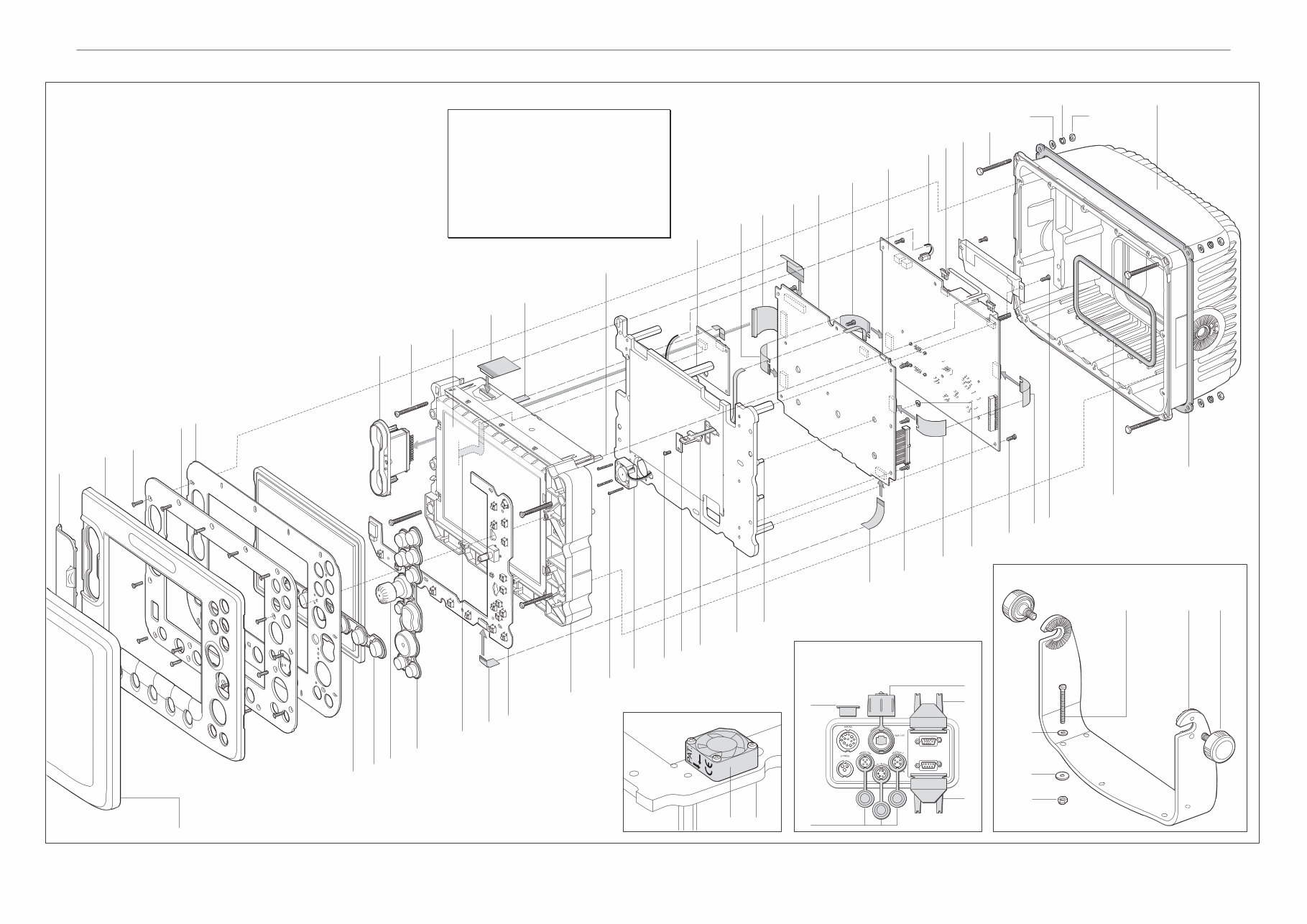
Exploded view
E80 Display Unit
D7747-1
42
15
17
19
19
43 (x2) 44 45 (x5)
Trunnion bracket kit
Fan orientation
46 (x5)
47 (x5)
48 (x5)
37 (x4)
14 (x4)
1 Chart door including seal
2 Bezel
3 Screw, M3 x 10 mm C'sk,
(x17), 6lb/in torque
4 Front plate
5 Window seal
6 Window
7 Lower keymat
8 Rotary control knob
9 Side keymat
10 Rowdriver flexi
11 Keyboard flexi
12 Keyboard PCB
13 Chartreader
14 Screw, M4 x 40 mm (x4),
10lb/in torque
15 LCD
16 LCD to CPU flexi
17 LCD extender flexi
18 Light box assembly
19 CCFL lamp connectors
20 Screw, M2.5 x 20 mm (x3),
5lb/in torque
21 Fan assembly
22 Screw, M3 x 6 mm (x14),
5lb/in torque
23 Retaining plate
24 Temperature sensor flexi
25 Heatsink plate
26 Post
27 Interface PCB
28 Chartreader flexi
29 CPU PCB
30 CPU to CCFL flexi (x2)
31 Fibre washer
32 CCFL PCB
33 Fan connector
34 High voltage shield
35 Screw, M4 x 40 mm,
Hex. Hd. (x4)
36 Plain washer, M4 (x4)
37 Spring washer, M4 (x4)
38 Nut, M4 (x4)
39
40
35 (x4)
26
31
10
Important information:
Please note the following when disassembling or reassembling
the Display:
* Read the safety notices at the front of this manual.
* Do not re-use seals.
* Do not scratch the finish on the front plate.
* Cover the window and LCD whenever they are exposed.
* Avoid handling the components of PCBs.
* Do not exceed the recommended torque values.
Failure to follow these may effect the operability or even cause
permanent damage to the unit.
14 (x4)
39 Rear cover
40 Connector panel seal
41 Flush mount seal
42 Suncover
43 Trunnion knob (x2)
44 Trunnion bracket
45 M6 x 50mm bolt (x5)
46 Washer (x5)
47 Button washer (x5)
48 Nut, Nyloc (x5)
49 Video in/VGA out blanking plugs
50 SeaTalk
HS
blanking plug
51 Radar dust cover
52 NMEA, SeaTalk/Alarm out
& SeaTalk
2
dust covers
Page 10 E-Series - Service Manual
47 (x5)
48 (x5)
46 (x5)
45 (x5)
44
43 (x2)
50
Trunnion bracket kit
Rear Connectors: Important
Fan orientation
49
49
51
52
22 (x3)
D7866_1
To avoid water ingress, always fit the blanking plugs
(49 & 50) when cables are disconnected.
25
21
1 Chart door including seal
2 Bezel
3 Screw, M3 x 10 mm C'sk,
(x19), 6lb/in torque
4 Front plate
5 Window seal
6 Window
7 Lower keymat
8 Rotary control knob
9 Lower side keymat
10 Upper side keymat
11 Keyboard flexi
12 Keyboard PCB
13 Chartreader
14 Screw, M4 x 40 mm (x6),
10lb/in torque
15 LCD
16 LCD to CPU flexi
17 Window spacer
18 Light box assembly
19 CCFL lamp connectors
20 Screw, M2.5 x 20 mm (x3),
5lb/in torque
21 Fan assembly
22 Screw, M3 x 6 mm (x 15),
5lb/in torque
23 Retaining plate
24 Temperature sensor flexi
25 Heatsink plate
26 Post
27 Cable tidy
28 Chartreader flexi
29 CPU PCB
30 CPU to CCFL flexi (x2)
31 Fibre washer
32 CCFL PCB
33 Fan connector
34 High voltage shield
35 Screw, M4 x 40 mm,
Hex. Hd. (x4)
36 Plain washer, M4 (x4)
37 Spring washer, M4 (x4)
38 Nut, M4 (x4)
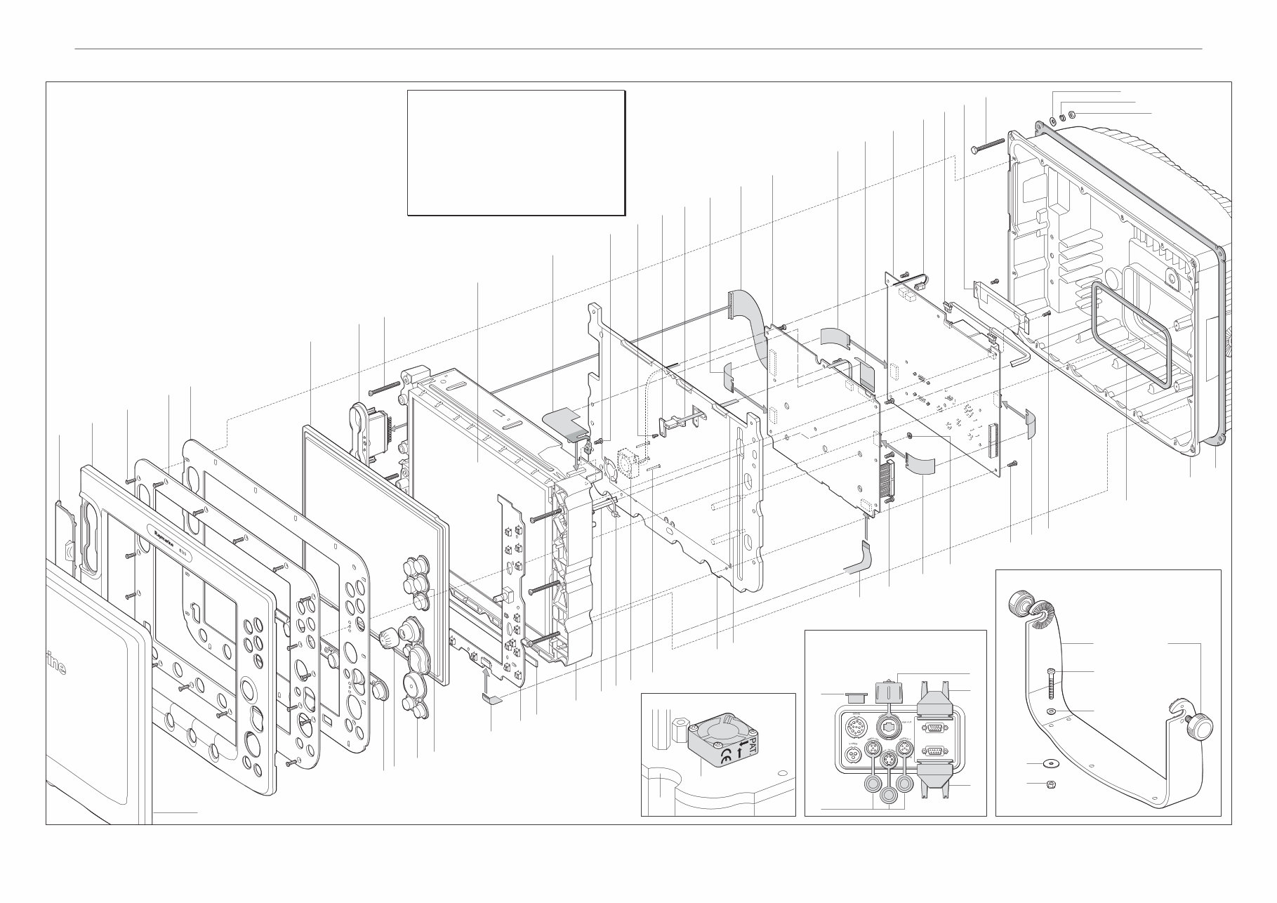
Exploded view
E120 Display Unit
Important information:
Please note the following when disassembling or reassembling
the Display:
* Read the safety notices at the front of this manual.
* Do not re-use seals.
* Do not scratch the finish on the front plate.
* Cover the window and LCD whenever they are exposed.
* Avoid handling the components of PCBs.
* Do not exceed the recommended torque values.
Failure to follow these may effect the operability or even cause
permanent damage to the unit.
1
2
3 (x19)
4
5
6
13
16
22
16
28
29
30
32
34
33
37(x4)
14 (x6)
22
23
24
25
35 (x4)
30
30
22 (x2)
15
19
38 (x4)
41
39
40
36 (x4)
7
9
11
11
18
20 (x3)
22 (x8)
12
8
42
17
19
27
21
26
10
30
31
39 Rear cover
40 Connector panel seal
41 Flush mount seal
42 Suncover
43 Trunnion knob (x2)
44 Trunnion bracket
45 M6 x 50mm bolt (x5)
46 Washer (x5)
47 Button washer (x5)
48 Nut, Nyloc (x5)
49 Video in/VGA out blanking plugs
50 SeaTalk
HS
blanking plug
51 Radar dust covers
52 NMEA, SeaTalk/Alarm out
& SeaTalk
2
dust covers.
Page 11 E-Series Displays - Service Manual
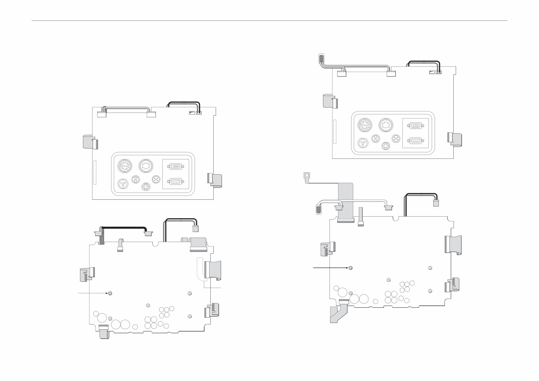
Plan of flexis and connectors
These illustrations show the location of the flexis and connectors attached to/from the CPU and CCFL PCBs. The
numbers in brackets refer to the item numbers shown in the exploded views on page 9 and 10 and in the dismantling
and reassembly instructions of this manual on page 5.
E80 Display
CCFL PCB
CPU PCB
E120 Display
CCFL PCB
CPU PCB
CPU to C
flexi (30)
CPU to CCFL
flexi (30)
CCFL lamp connectors (19)
Fan connector (33)
CCFL PCB (32)
D7842_1
CPU to CCFL
flexi (30)
CPU to CCFL
flexi (30)
Fibre
washer (31)
Keyboard flexi (11)
CCFL lamp connectors (19)
Temperature
sensor flexi (24)
Fan connector (33)
LCD to CPU
flexi (16)
LCD extender
flexi (17)
Chartreade
flexi (28)
Rowdriver
flexi (10)
CPU PCB (29)
D7841_1
CPU to C
flexi (30)
CPU to CCFL
flexi (30)
CCFL lamp connectors (19)
Fan connector (33)
CCFL PCB (32)
D7868_1
CPU to CCFL
flexi (30)
CPU to CCFL
flexi (30)
Keyboard flexi (11)
CCFL lamp connectors (19)
Temperature
sensor flexi (24)
Fan connector (33)
LCD to CPU flexi (16)
Chartreade
flexi (28)
CPU PCB (29)
Fibre
washer (31)
D7867_1

Page 13 E-Series Displays - Service Manual
Parts list
The following items are available as parts for the E-Series Display. The items numbers noted in these lists correspond
to the numbers in the exploded views on pages 9 and 10.
E120
E80
Description Includes item numbers(s) Part number
Suncover 42 R58195
Chart door 1 R58210
Bezel 1, 2 R58194
Seal set 5, 40 R58197
Keymats 7, 9, 10 R08006
Rotary control knob 8 R08055
Window 6 R08036
Chartreader 13 R58202
Keyboard PCB 12 R58216
Light box assembly 15, 16, 19, 20, 21, 22, 23, 24, 25, 33 R58192
Fan assembly/connector 21,33 R58203
CPU PCB 29 R58187
CCFL PCB 32 R58176
Flush mount seal 41 R58193
Trunnion mount kit 43, 44, 45, 46, 47, 48 R58205
Trunnion knob (x2) 43 R08001
LCD to CPU flexi 16 R58191
CPU to CCFL flexi 30 R58200
Keyboard flexi 11 R58190
Temperature sensor/flexi 24 R58201
Chartreader flexi 28 R58189
SeaTalk/Alarm out cable not illustrated R08050
NMEA cable not illustrated R08004
Power cable (1.5m) not illustrated R89005
Radar dust cap 51 R08131
Video in/VGA out blanking plug 49 R08153
Description Includes item numbers(s) Part number
Suncover 42 R58184
Chart door 1 R58210
Bezel 1, 2 R58183
Seal set 5, 40 R58186
Keymats 7, 9 R08006
Rotary control knob 8 R08055
Window 6 R08025
Chartreader 13 R58202
Keyboard PCB 12 R58215
Light box assembly 15, 16, 19, 20, 21, 22, 23, 24, 25, 33 R58179
Fan assembly/connector 21,33 R58203
CPU PCB 29 R58175
Interface PCB 27 R58198
CCFL PCB 32 R58176
Flush mount seal 41 R58182
Trunnion mount kit 43, 44, 45, 46, 47, 48 R58204
Trunnion knob (x2) 43 R08001
LCD to CPU flexi 16 R58177
LCD extender flexi 17 R58178
CPU to CCFL flexi 30 R58200
Keyboard flexi 11 R58180
Temperature sensor/flexi 24 R58201
Chartreader flexi 28 R58181
SeaTalk/Alarm out cable not illustrated R08050
NMEA cable not illustrated R08004
Power cable (1.5m) not illustrated R89005
Radar dust cap 51 R08131
Video in/VGA out blanking plug 49 R08153
You're Reading a Preview
What's Included?
Fast Download Speeds
Online & Offline Access
Access PDF Contents & Bookmarks
Full Search Facility
Print one or all pages of your manual
$31.99
Viewed 22 Times Today


Secure transaction
What's Included?
Fast Download Speeds
Online & Offline Access
Access PDF Contents & Bookmarks
Full Search Facility
Print one or all pages of your manual
$31.99
The Raymarine E-Series Classic E80 & E120 Service Manual is an essential resource for both professional mechanics and DIY enthusiasts. It contains important information, safety notices, dismantling and reassembly instructions, exploded views, plan of flexis and connectors, parts list, system diagnostics, as well as PCB and circuit diagrams. Whether you're troubleshooting, repairing, or maintaining your E-Series Classic E80 & E120, this manual provides comprehensive guidance to ensure the job is done accurately and efficiently.


