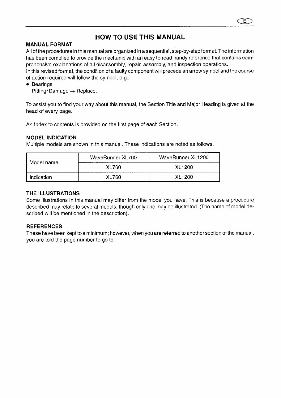
HOW TO USE THIS MANUAL MANUAL FORMAT All of the procedures in this manual are organized in a sequential, step-by-step format. The information has been complied to provide the mechanic with an easy to read handy reference that contains com- prehensive explanations of all disassembly, repair, assembly, and inspection operations. In this revised format, the condition of a faulty component will precede an arrow symbol and the course of action required will follow the symbol, e.g., • Bearings Pitting/Damage --+ Replace. To assist you to find your way about this manual, the Section Title and Major Heading is given at the head of every page. An Index to contents is provided on the first page of each Section. MODEL INDICATION Multiple models are shown in this manual. These indications are noted as follows. WaveRunner XL760 Wave Runner XL 1200 Model name XL760 XL1200 Indication XL760 XL1200 THE ILLUSTRATIONS Some illustrations in this manual may differ from the model you have. This is because a procedure described may relate to several models, though only one may be illustrated. (The name of model de- scribed will be mentioned in the description). REFERENCES These have been kept to a minimum; however, when you are referred to another section of the manual, you are told the page number to go to.
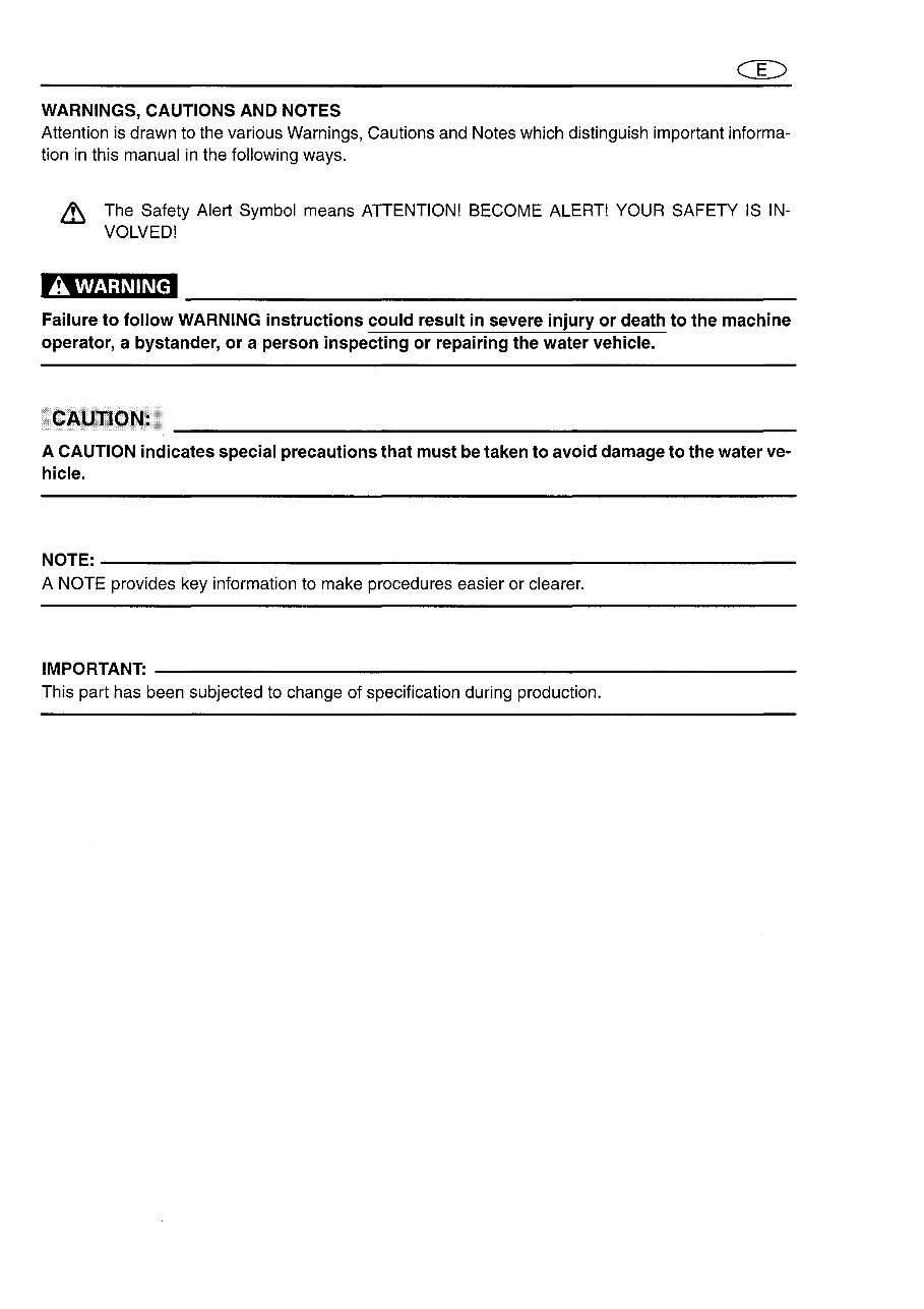
WARNINGS, CAUTIONS AND NOTES Attention is drawn to the various Warnings, Cautions and Notes which distinguish important informa- tion in this manual in the following ways. & The Safety Alert Symbol means ATTENTION! BECOME ALERT! YOUR SAFETY IS IN- VOLVED! A WARNING Failure to follow WARNING instructions could result in severe injury or death to the machine operator, a bystander, or a person inspecting or repairing the water vehicle . . CAUTION: A CAUTION indicates special precautions that must be taken to avoid damage to the water ve- hicle. NOTE:----------------------------------------------------------- A NOTE provides key information to make procedures easier or clearer. IMPORTAN~ ------------------------------------------------------ This part has been subjected to change of specification during production.
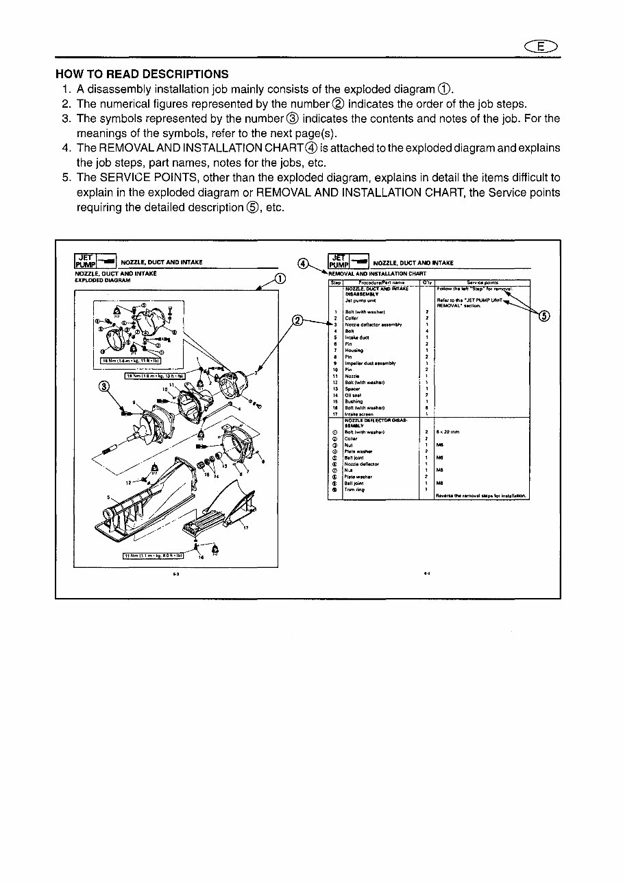
HOW TO READ DESCRIPTIONS 1. A disassembly installation job mainly consists of the exploded diagram CD. 2. The numerical figures represented by the number ® indicates the order of the job steps. 3. The symbols represented by the number @ indicates the contents and notes of the job. For the meanings of the symbols, refer to the next page(s). 4. The REMOVAL AND INSTALLATION CHART@ is attached to the exploded diagram and explains the job steps, part names, notes for the jobs, etc. 5. The SERVICE POINTS, other than the exploded diagram, explains in detail the items difficult to explain in the exploded diagram or REMOVAL AND INSTALLATION CHART, the Service points requiring the detailed description ®, etc. l"tJUpl--1 NOZZLE. DUCT AND INTAKE NOZZLE, DUCT AND INTAKE EXPLODED DIAGRAM l'4L 1~~pl--1 NOZZLE, DUCT AND INTAKE ~ ~REMOVAl AND INSTAllATION CHART 100 I. 11 12 13 ,. 15 ,. n <D (j) (j) tj) (j) <il (!) (j) (j) tD rocedur. ,"~m. NOZZlE. DUCT AND INTAKE DlSASSEMIlV Jet pump unit Bolt (with wI.h,r' CollI( Nonie deflector .... mbty 80" Inl.ke duet Pin Houslng Pin Impen., duct ".embty Pin NOllie Bolt Iwith washer) St*=8' 011 .. ,1 Bushing 801t (with w •• her) Inllklscr',n NOULE DEFLECTOR DfSAS· IEMBlY Bolt (with w .. h,r) Coli" Nul PII1I wisher 8.lIioint Noule def&tctor Nut Pletew"h" a,II;oint Trlmrlnv IV R,f.t to the "JET PUMP UNIT REMOVAL- hCtion. 2 8><20mm M8 Rev.rse the remov.1 steps for mll.n-lion. ,.,
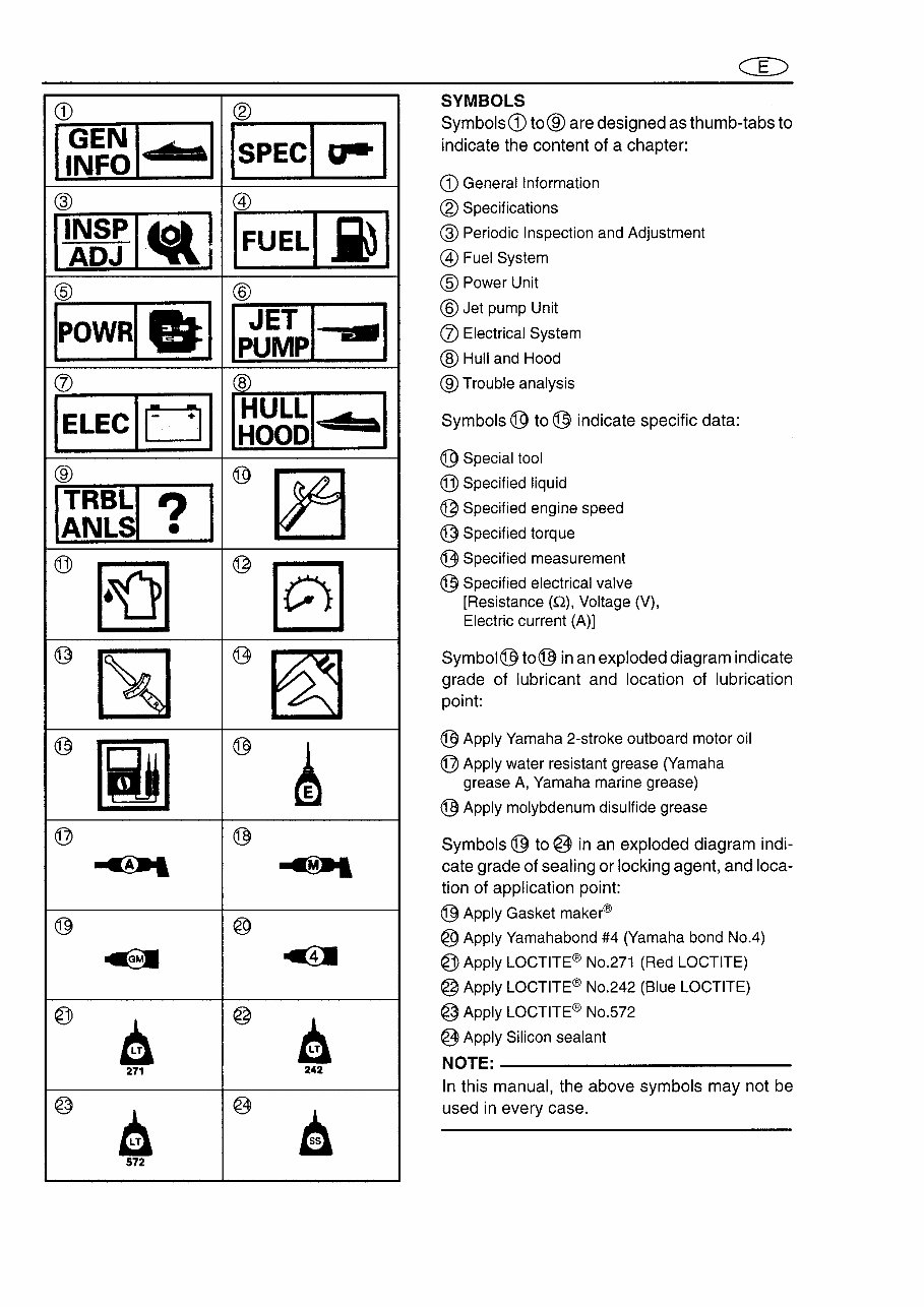
CD ® I~~I IIiI . I ISPECI r I @ @ P~gSI~1 IFUELI ,i) I @ @ IPOWRI&I Ipt~pl .. I (J) ~ IELEClul HULL • • HOOD ® Il~~~ ? I ® ~ @ ~ @ ~ @ ~ ~ ~ ® [iJ ® ~ @ ® ~ ~ @ @ ~ ~ @ A @ A 271 242 @ • @ a 572 CD SYMBOLS Symbols CD to® are designed as thumb-tabs to indicate the content of a chapter: CD General Information ® Specifications @ Periodic Inspection and Adjustment @ Fuel System @ Power Unit @ Jet pump Unit (J) Electrical System ® Hull and Hood ® Trouble analysis Symbols ® to ® indicate specific data: ® Special tool @ Specified liquid @ Specified engine speed @ Specified torque ~ Specified measurement ® Specified electrical valve [Resistance (Q), Voltage (V), Electric current (A)] Symbol® to® in an exploded diagram indicate grade of lubricant and location of lubrication point: ® Apply Yamaha 2-stroke outboard motor oil @ Apply water resistant grease (Yamaha grease A, Yamaha marine grease) ® Apply molybdenum disulfide grease Symbols @ to @ in an exploded diagram indi- cate grade of sealing or locking agent, and loca- tion of application point: @ Apply Gasket maker@ @ Apply Yamahabond #4 (Yamaha bond No.4) @ Apply LOCTITE@ No.271 (Red LOCTITE) @ Apply LOCTITE@ No.242 (Blue LOCTITE) @ Apply LOCTITE@ No.S72 @ Apply Silicon sealant NOTE:------------------------- In this manual, the above symbols may not be used in every case.
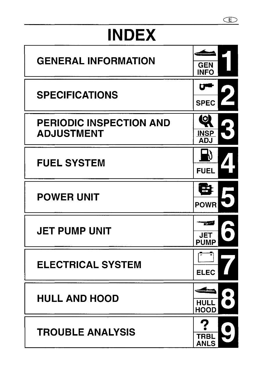
INDEX GENERAL INFORMATION SPECIFICATIONS PERIODIC INSPECTION AND ADJUSTMENT FUEL SYSTEM POWER UNIT JET PUMP UNIT ELECTRICAL SYSTEM HULL AND HOOD TROUBLE ANALYSIS GEN INFO o ? •
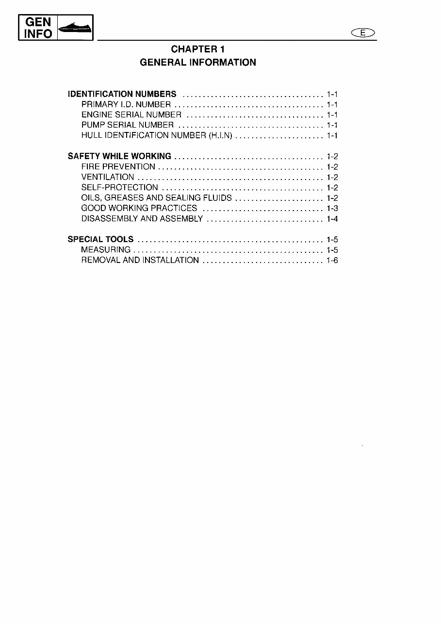
CHAPTER 1 GENERAL INFORMATION IDENTIFICATION NUMBERS ................................... 1-1 PRIMARY I.D. NUMBER ..................................... 1-1 ENGINE SERIAL NUMBER .................................. 1-1 PUMP SERIAL NUMBER .................................... 1-1 HULL IDENTIFICATION NUMBER (H.I.N) ...................... 1-1 SAFETY WHILE WORKING . .................................... 1-2 FIRE PREVENTION ......................................... 1-2 VENTILATION .............................................. 1-2 SELF-PROTECTION ........................................ 1-2 OILS, GREASES AND SEALING FLUiDS ...................... 1-2 GOOD WORKING PRACTiCES .............................. 1-3 DISASSEMBLY AND ASSEMBLy ............................. 1-4 SPECIAL TOOLS .............................................. 1-5 MEASURING ............................................... 1-5 REMOVAL AND INSTALLATION .............................. 1-6
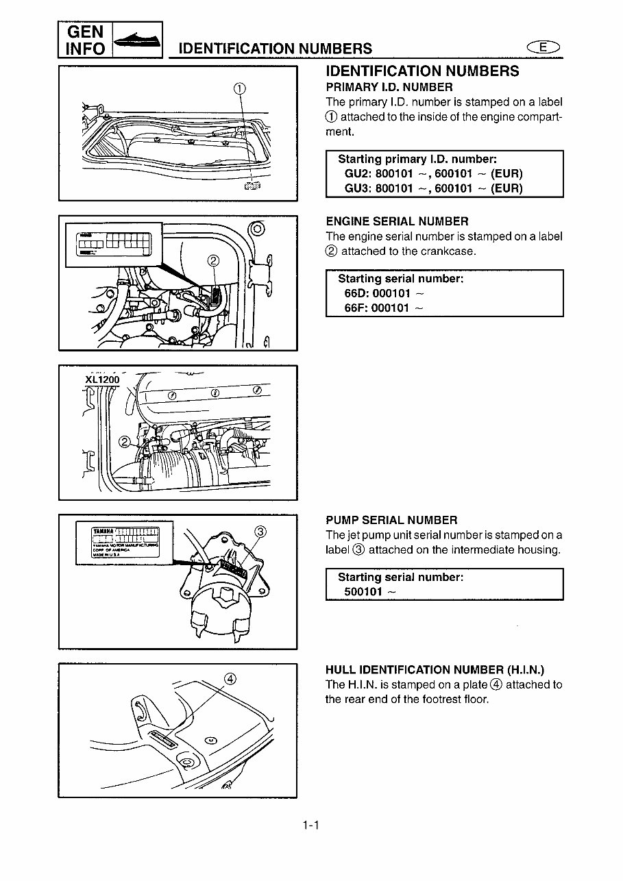
1~~I+cl_ID_E_N_TI_F_IC_A_TI_O_N_N_U_M_B_E_R_S _______ C_~_~_ t\ 61 1-1 IDENTIFICATION NUMBERS PRIMARY 1.0. NUMBER The primary 1.0. number is stamped on a label CD attached to the inside of the engine com part- ment. Starting primary 1.0. number: GU2: 800101 -,600101 - (EUR) GU3: 800101 -,600101 - (EUR) ENGINE SERIAL NUMBER The engine serial number is stamped on a label ® attached to the crankcase. Starting serial number: 660: 000101 - 66F:000101 - PUMP SERIAL NUMBER The jet pump unit serial number is stamped on a label @ attached on the intermediate housing. Starting serial number: 500101 - HULL IDENTIFICATION NUMBER (H.I.N.) The H.I.N. is stamped on a plate@ attached to the rear end of the footrest floor.
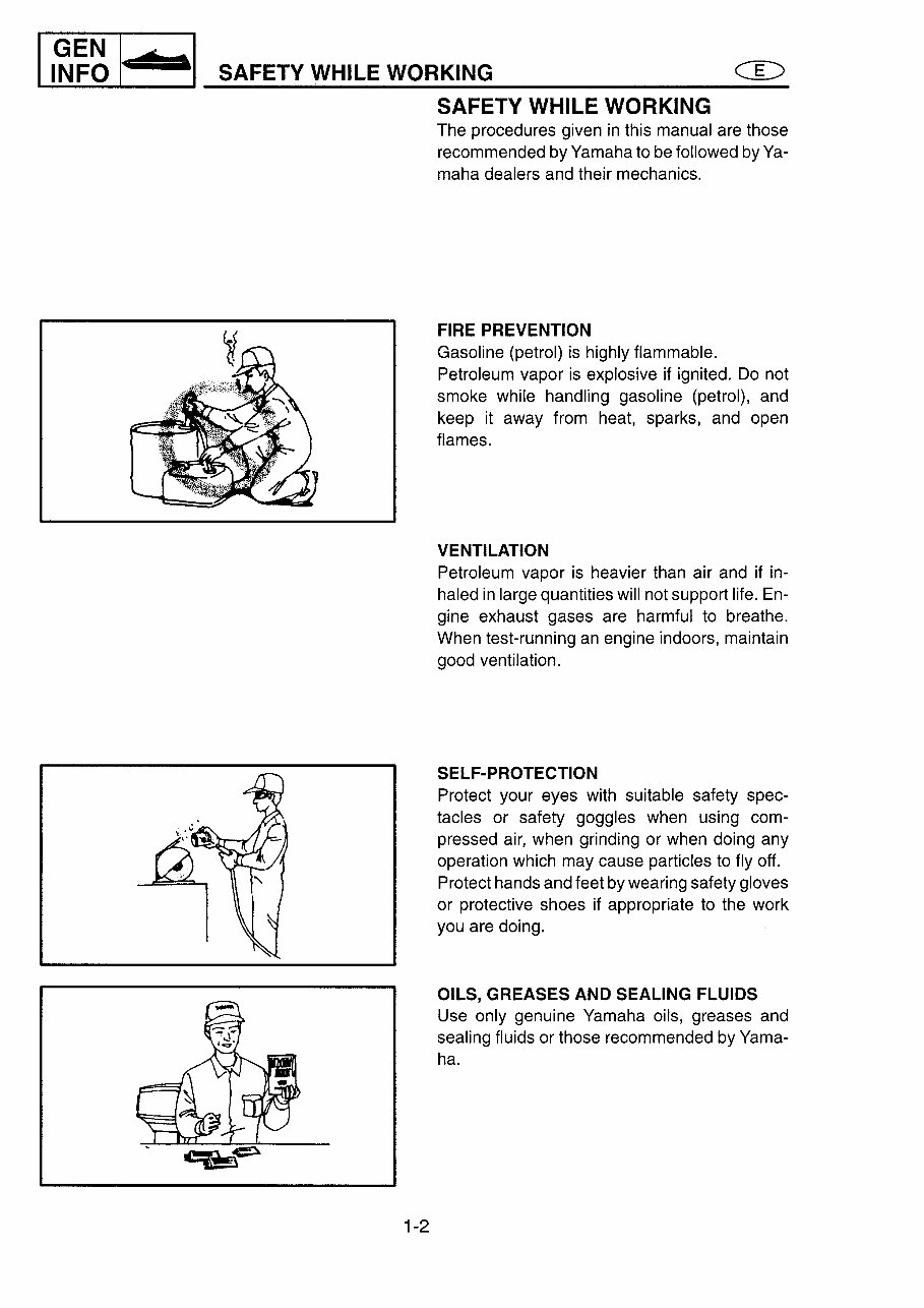
~IG~~EF~NO~6_'_rt~I _____ ~ _________________________ C_gE_~_ _ . SAFETY WHILE WORKING 1-2 SAFETY WHILE WORKING The procedures given in this manual are those recommended by Yamaha to be followed by Ya- maha dealers and their mechanics. FIRE PREVENTION Gasoline (petrol) is highly flammable. Petroleum vapor is explosive if ignited. Do not smoke while handling gasoline (petrol), and keep it away from heat, sparks, and open flames. VENTILATION Petroleum vapor is heavier than air and if in- haled in large quantities will not support life. En- gine exhaust gases are harmful to breathe. When test-running an engine indoors, maintain good ventilation. SELF-PROTECTION Protect your eyes with suitable safety spec- tacles or safety goggles when using com- pressed air, when grinding or when doing any operation which may cause particles to fly off. Protect hands and feet by wearing safety gloves or protective shoes if appropriate to the work you are doing. OILS, GREASES AND SEALING FLUIDS Use only genuine Yamaha oils, greases and sealing fluids or those recommended by Yama- ha.
The Yamaha WaveRunner XL760 1998 Factory Service Repair Manual is a comprehensive resource for repairing and adjusting your watercraft. It is designed to be user-friendly and beneficial for both professional mechanics and DIY enthusiasts.
This manual encompasses detailed explanations of installation, removal, disassembly, assembly, repair, and check procedures, presented in a sequential order for ease of understanding.
It is known by various names such as the Yamaha WaveRunner XL760 1998 service manual, repair manual, workshop manual, and shop manual, all of which refer to the same manual.
Upon purchase, immediate access to the manual allows for prompt completion of tasks.
The manual is organized into chapters, each covering specific aspects:
General information
Specifications
Periodic inspections and adjustments
Fuel system
Power unit
Jet pump unit
Electrical systems
Hull and hood
Trouble analysis
Each chapter is further divided into sections, with each section containing sub-sections. The manual includes exploded diagrams at the beginning of each removal and disassembly section to aid in part identification and procedure clarification.
The manual is available in a FORMAT, allowing for the convenient printing of specific pages or the entire manual as needed.
Recently Viewed
5,521,897Happy Clients
2,594,462eManuals
1,120,453Trusted Sellers
15Years in Business
Price:
Actual Price:
1998 Yamaha WaveRunner XL760 Service & Repair Manual