LIT186160198 LIT-18616-01-98 F0D-28197-Z9-11 SERVICE MANUAL WaveRunner XL1200Ltd
E NOTICE This manual has been prepared by the Yamaha Motor Company Ltd. primarily for use by Yamaha dealers and their trained mechanics when performing maintenance procedures and repairs to Yamaha equipment. It has been written to suit the needs of persons who have a basic understanding of the mechanical and electrical concepts and procedures inherent in the work, for without such knowledge attempted repairs or service to the equipment could render it unsafe or unfit for use. Because the Yamaha Motor Company, Ltd. has a policy of continuously improving its prod- ucts, models may differ in detail from the descriptions and illustrations given in this publica- tion. Use only the latest edition of this manual. Authorized Yamaha dealers are notified periodically of modifications and significant changes in specifications and procedures, and these are incorporated in successive editions of this manual. A10001-0* WaveRunner XL1200Ltd SERVICE MANUAL 1999 Yamaha Motor Co., Ltd. 1st Edition, March 1999 All rights reserved. No part of this publication may be reproduced or transmitted in any form or by any means including photocopying and recording without the written permission of the copyright holder. Such written permission must also be obtained before any part of this publication is stored in a retrieval system of any nature. Printed in USA LIT-18616-01-98
E HOW TO USE THIS MANUAL MANUAL FORMAT All of the procedures in this manual are organized in a sequential, step-by-step format. The information has been compiled to provide the mechanic with an easy to read, handy refer- ence that contains comprehensive explanations of all disassembly, repair, assembly, and inspection operations. In this revised format, the condition of a faulty component will precede an arrow symbol and the course of action required will follow the symbol, e.g., ● Bearings Pitting/scratches → Replace. To assist you in finding your way through this manual, the section title and major heading is given at the top of every page. ILLUSTRATIONS The illustrations within this service manual represent all of the designated models. CROSS REFERENCES The cross references have been kept to a minimum. Cross references will direct you to the appropriate section or chapter.
E IMPORTANT INFORMATION In this Service Manual particularly important information is distinguished in the following ways. The Safety Alert Symbol means ATTENTION! BECOME ALERT! YOUR SAFETY IS INVOLVED! WARNING Failure to follow WARNING instructions could result in severe injury or death to the machine operator, a bystander, or a person inspecting or repairing the water vehicle. CAUTION: A CAUTION indicates special precautions that must be taken to avoid damage to the water vehicle. NOTE: A NOTE provides key information to make procedures easier or clearer. IMPORTANT: This part has been subjected to change of specification during production.
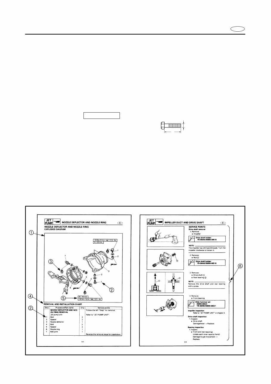
E HOW TO USE THIS MANUAL 1 To help identify parts and clarify procedure steps, there are exploded diagrams at the start of each removal and disassembly section. 2 Numbers are given in the order of the jobs in the exploded diagram. 3 Symbols indicate parts to be lubricated or replaced (see “SYMBOLS”). 4 A job instruction chart accompanies the exploded diagram, providing the order of jobs, names of parts, notes in jobs, etc. 5 Dimension figures and the number of parts, are provided for fasteners that require a tight- ening torque. Example: Bolt or screw size : M10 (D) × 25 mm (L) 6 Jobs requiring more information (such as special tools and technical data) are described sequentially. 10 × 25 mm D L
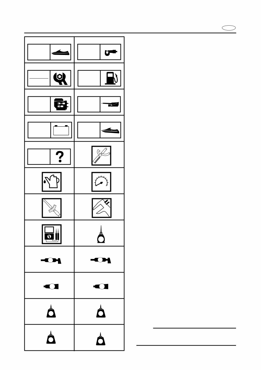
E A50001-1-4 SYMBOLS Symbols 1 to 9 are designed as thumb- tabs to indicate the content of a chapter. 1 General Information 2 Specifications 3 Periodic Inspection and Adjustment 4 Fuel System 5 Power Unit 6 Jet Pump Unit 7 Electrical System 8 Hull and Hood 9 Trouble-analysis Symbols 0 to E indicate specific data: 0 Special tool A Specified liquid B Specified engine speed C Specified torque D Specified measurement E Specified electrical value [Resistance (Ω), Voltage (V), Electric current (A)] Symbol F to H in an exploded diagram indicate the grade of lubricant and the loca- tion of lubrication point: F Apply YAMALUBE 2-W oil G Apply water resistant grease (Yamaha grease A, Yamaha marine grease) H Apply molybdenum disulfide grease Symbols I to N in an exploded diagram indicate the grade of the sealing or locking agent, and the location of the application point: I Apply Gasket Maker J Apply Yamabond #4 (Yamaha bond number 4) K Apply LOCTITE No. 271 (Red LOCTITE) L Apply LOCTITE No. 242 (Blue LOCTITE) M Apply LOCTITE No. 572 N Apply silicone sealant NOTE: In this manual, the above symbols may not be used in every case. 1 2 3 4 5 6 7 8 9 0 A B C D E F G H I J K L M N GEN INFO SPEC INSP ADJ FUEL POWR JET PUMP – + ELEC HULL HOOD TRBL ANLS T R . . E A M GM 4 271 LT 242 LT 572 LT SS
E INDEX GENERAL INFORMATION 1 SPECIFICATIONS 2 SPEC PERIODIC INSPECTION AND ADJUSTMENT 3 FUEL SYSTEM 4 FUEL POWER UNIT 5 POWR JET PUMP UNIT 6 JET PUMP ELECTRICAL SYSTEM 7 ELEC HULL AND HOOD 8 HULL HOOD TROUBLE-ANALYSIS 9 GEN INFO INSP ADJ – + TRBL ANLS A30000-0
E 1 2 3 4 5 6 7 8 9 GEN INFO CHAPTER 1 GENERAL INFORMATION IDENTIFICATION NUMBERS ......................................................................... 1-1 PRIMARY l.D. NUMBER........................................................................... 1-1 ENGINE SERIAL NUMBER ...................................................................... 1-1 JET PUMP UNIT SERIAL NUMBER ........................................................ 1-1 HULL IDENTIFICATION NUMBER (H.l.N.) .............................................. 1-1 SAFETY WHILE WORKING ....................................................................... 1-2 FIRE PREVENTION ................................................................................... 1-2 VENTILATION........................................................................................... 1-2 SELF-PROTECTION.................................................................................. 1-2 OILS, GREASES AND SEALING FLUIDS................................................ 1-2 GOOD WORKING PRACTICES ................................................................ 1-3 DISASSEMBLY AND ASSEMBLY ........................................................... 1-4 SPECIAL TOOLS ............................................................................................. 1-5 MEASURING ............................................................................................ 1-5 REMOVAL AND INSTALLATION ............................................................ 1-6
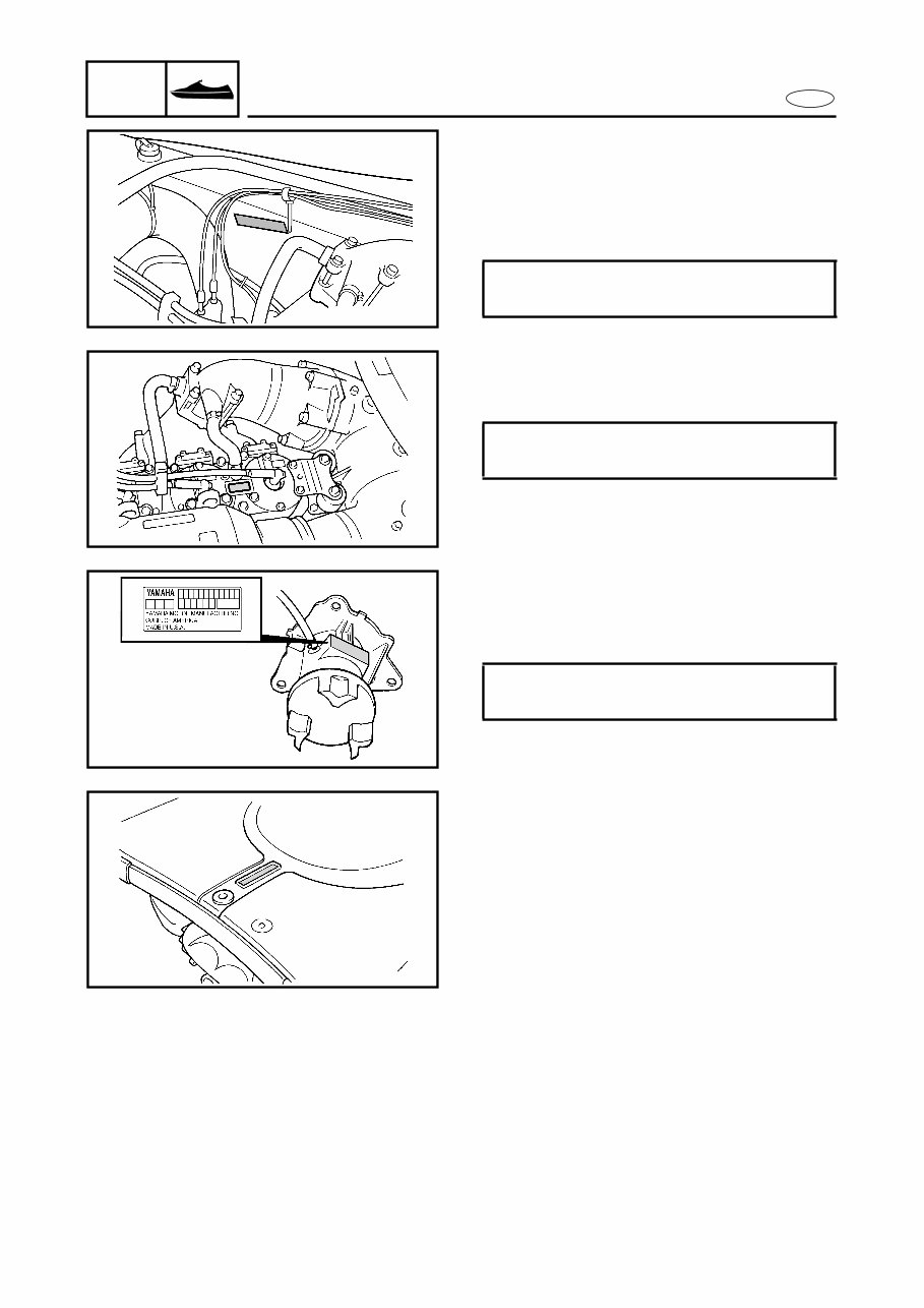
1-1 E GEN INFO IDENTIFICATION NUMBERS A60700-0* IDENTIFICATION NUMBERS PRIMARY l.D. NUMBER The primary l.D. number is stamped on a label attached to the inside of the engine compartment. Starting primary l.D. number: F0D: 800101 ~ ENGINE SERIAL NUMBER The engine serial number is stamped on a label attached to the cylinder head. Starting serial number: 66V: 000101 ~ JET PUMP UNIT SERIAL NUMBER The jet pump unit serial number is stamped on a label attached to the intermediate housing. Starting serial number: 66V: 800101 ~ HULL IDENTIFICATION NUMBER (H.l.N.) The H.l.N. is stamped on a plate attached to the aft deck.
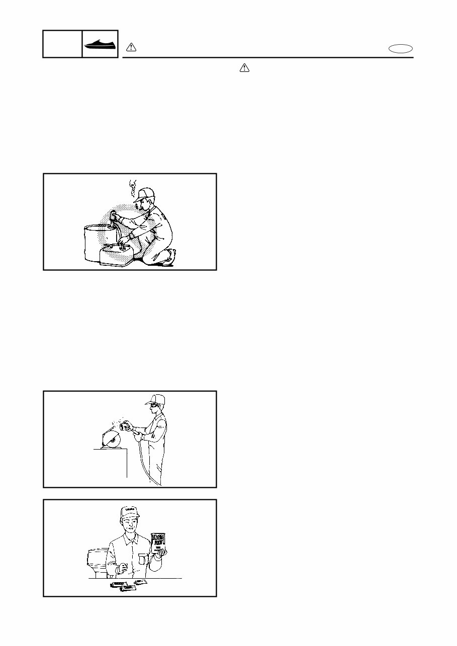
1-2 E GEN INFO SAFETY WHILE WORKING SAFETY WHILE WORKING The procedures given in this manual are those recommended by Yamaha to be fol- lowed by Yamaha dealers and their mechanics. FIRE PREVENTION Gasoline (petrol) is highly flammable. Petroleum vapor is explosive if ignited. Do not smoke while handling gasoline (petrol) and keep it away from heat, sparks, and open flames. VENTILATION Petroleum vapor is heavier than air and is deadly if inhaled in large quantities. Engine exhaust gases are harmful to breathe. When test-running an engine indoors, maintain good ventilation. SELF-PROTECTION Protect your eyes with suitable safety spec- tacles or safety goggles when grinding or doing any operation which may cause parti- cles to fly off. Protect hands and feet by wearing safety gloves or protective shoes if appropriate to the work you are doing. OILS, GREASES AND SEALING FLUIDS Use only genuine Yamaha oils, greases, and sealing fluids or those recommended by Yamaha.
A 1999 Yamaha WaveRunner XL1200 LTD Service Manual is an essential resource for anyone looking to maintain or repair this specific watercraft model. Whether you are a professional mechanic or a DIY enthusiast, this manual provides detailed guidance on servicing, maintenance, and repair procedures.
With comprehensive sections covering engine, electrical system, hull and deck, and other crucial components, this manual equips you with the necessary information to keep your WaveRunner in top condition. It includes step-by-step instructions, diagrams, and illustrations to facilitate the repair and maintenance processes.
By referring to this manual, you can ensure that all service and repair tasks are performed accurately and efficiently, ultimately prolonging the life of your WaveRunner XL1200 LTD. Whether you are troubleshooting a specific issue or conducting routine maintenance, this manual is an invaluable resource for keeping your watercraft in optimal working condition.