


REPAIR MANUAL 2010-2015
WaveRunner
F2N-28197-1M-11
VX Sport
VX1100 (F2N)
VX Cruiser
VX1100A (F2N)
VX Deluxe
VX1100B (F2N)
LIT-18616-03-22
Preface
This manual has been prepared by Yamaha primarily for use by Yamaha dealers and their trained
mechanics when performing maintenance procedures and repairs to Yamaha equipment. It has
been written to suit the needs of persons who have a basic understanding of the mechanical and
electrical concepts and procedures inherent in the work, for without such knowledge attempted
repairs or service to the equipment could render it unsafe or unfit for use.
Because Yamaha has a policy of continuously improving its products, models may differ in detail
from the descriptions and illustrations given in this publication. Use only the latest edition of this
manual. Authorized Yamaha dealers are notified periodically of modifications and significant
changes in specifications and procedures, and these are incorporated in successive editions of this
manual. Also, up-to-date parts information is available on YPEC-web. Additional information and
up-to-date information on Yamaha products and services are available on Yamaha Service Portal.
Important information
Particularly important information is distinguished in this manual by the following notations:
The Safety Alert Symbol means ATTENTION! BECOME ALERT! YOUR SAFETY IS
INVOLVED!
A WARNING indicates a hazardous situation which, if not avoided, could result in death or
serious injury.
A NOTICE indicates special precautions that must be taken to avoid damages to the water-
craft or other property.
TIP:
A TIP provides key information to make procedures easier or clearer.
WaveRunner
VX Sport, VX Cruiser, VX Deluxe
SERVICE MANUAL
©2010 by Yamaha Motor Corporation, U.S.A.
1st Edition, January 2010
All rights reserved.
Any reprinting or unauthorized use
without the written permission of
Yamaha Motor Corporation, U.S.A.
is expressly prohibited.
Printed in U.S.A.
LIT-18616-03-22
Contents
General information
GEN
INFO
Specification
SPEC
Maintenance
MNT
Fuel system
FUEL
Power unit
POWR
Jet pump unit
JET
PUMP
Electrical system
ELEC
Hull and hood
HULL
HOOD
Troubleshooting
TRBL
SHTG
Appendix
– +
1
2
3
4
5
6
7
8
9
A

GEN
INFO
1
General information
Safety while working ..................................................... 1-1
Rotating part ............................................................................... 1-1
Hot part ....................................................................................... 1-1
Electric shock ............................................................................. 1-1
Impeller ....................................................................................... 1-1
Handling of gasoline ................................................................... 1-1
Ventilation................................................................................... 1-2
Self-protection ............................................................................ 1-2
Working with crane ..................................................................... 1-2
Handling of heat gun .................................................................. 1-3
Part, lubricant, and sealant ......................................................... 1-3
Handling of sealant ..................................................................... 1-3
Special service tool .................................................................... 1-3
Tightening torque ....................................................................... 1-3
Non-reusable part ....................................................................... 1-3
Disassembly and assembly ........................................................ 1-4
How to use this manual ..................................................... 1-5
Manual format ............................................................................ 1-5
Abbreviation ............................................................................... 1-6
Adhesive, lubricant, sealant,
and thread locking agent ................................................... 1-7
Symbol ....................................................................................... 1-7
Special service tool ............................................................ 1-8
Model feature .................................................................... 1-15
General feature ........................................................................ 1-15
Identification number ................................................................ 1-16
Deck and hull ............................................................................ 1-17
Intermediate drive shaft ............................................................ 1-18
ECM and rectifier regulator ...................................................... 1-19
Multifunction meter unit ............................................................ 1-20
Multifunction display warning ................................................... 1-21
Yamaha Security System (VX Cruiser and VX Deluxe) ........... 1-22
Technical tips ................................................................... 1-23
Engine control .......................................................................... 1-23
Engine control system .............................................................. 1-28
1-1
GEN
INFO
General information
Safety while working
To prevent an accident or injury and to pro-
vide quality service, observe the following
safety procedures.
Rotating part
• Hands, feet, hair, jewelry, clothing, per-
sonal flotation device straps, and so on,
can become entangled with internal rotating
parts of the engine or jet pump unit, result-
ing in serious injury or death.
• Keep hands, feet, hair, jewelry, clothing,
personal flotation device straps, and so on,
away from any exposed moving parts when
operating the engine with the seat
removed.
• Keep away from intake grate while engine
is on. Items such as hair, clothing, or per-
sonal flotation device straps can become
entangled in moving parts resulting in
severe injury.
Hot part
During and after operation, engine parts are
hot enough to cause burns. Do not touch any
parts in the engine compartment until the
engine has cooled.
Electric shock
Do not touch any electrical parts while start-
ing or operating the engine. Otherwise, shock
or electrocution could result.
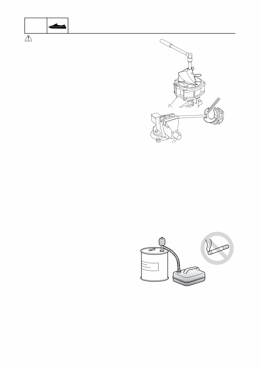
Impeller
Do not hold the impeller with your hands
when loosening or tightening the impeller.
Handling of gasoline
• Gasoline is highly flammable. Keep gaso-
line and all flammable products away from
heat, sparks, and open flames.
• Gasoline is poisonous and can cause injury
or death. Handle gasoline with care. Never
siphon gasoline by mouth. If you swallow
some gasoline, inhale a lot of gasoline
vapor, or get some gasoline in your eyes,
see your doctor immediately. If gasoline
spills on your skin, wash with soap and
water. If gasoline spills on your clothing,
change your clothes.
1-2
1
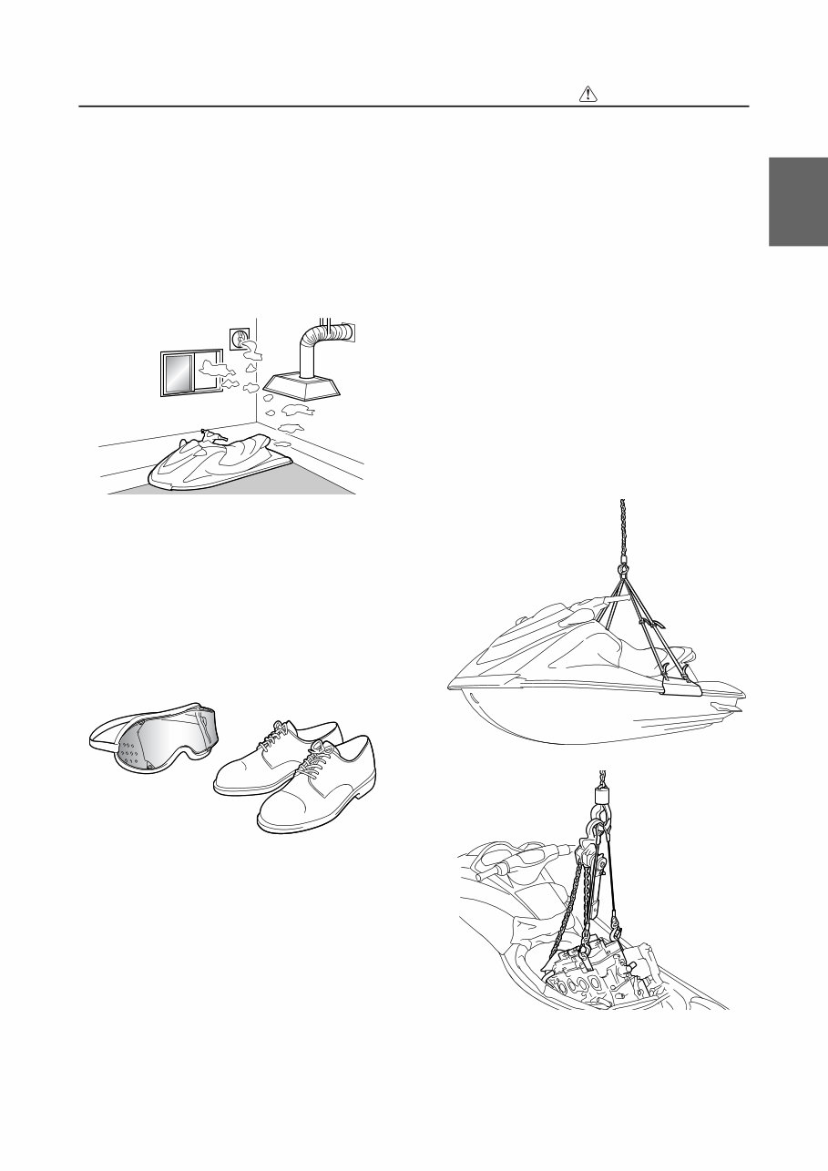
Ventilation
• Gasoline vapor and exhaust gas are
heavier than air and extremely poisonous.
If gasoline vapor or exhaust gas is inhaled
in large quantities, it may cause loss of con-
sciousness and death within a short time.
• When test running an engine indoors (for
example, in a water tank) make sure to do
so where adequate ventilation can be main-
tained.
Self-protection
• Protect your eyes by wearing safety
glasses or safety goggles during all opera-
tions involving drilling and grinding, or when
using an air compressor.
• Protect your hands and feet by wearing
protective gloves and safety shoes when
necessary.
Working with crane
• When moving the watercraft, or when lifting
the engine during removal or installation,
make sure to use a crane with a lifting
capacity that is equal to or more than the
weight of the watercraft or engine respec-
tively.
• When lifting the watercraft, use the water-
craft lift harness and make sure that the
watercraft is in a stable position when mov-
ing it.
• Use the wire ropes of adequate strength,
and lift up the engine unit using the three
point suspension.
• If the engine unit does not have three or
more points to be suspended, support it
using additional ropes or the like so that the
engine unit can be lifted and carried in a
stable manner.
Safety while working
1-3
GEN
INFO
General information
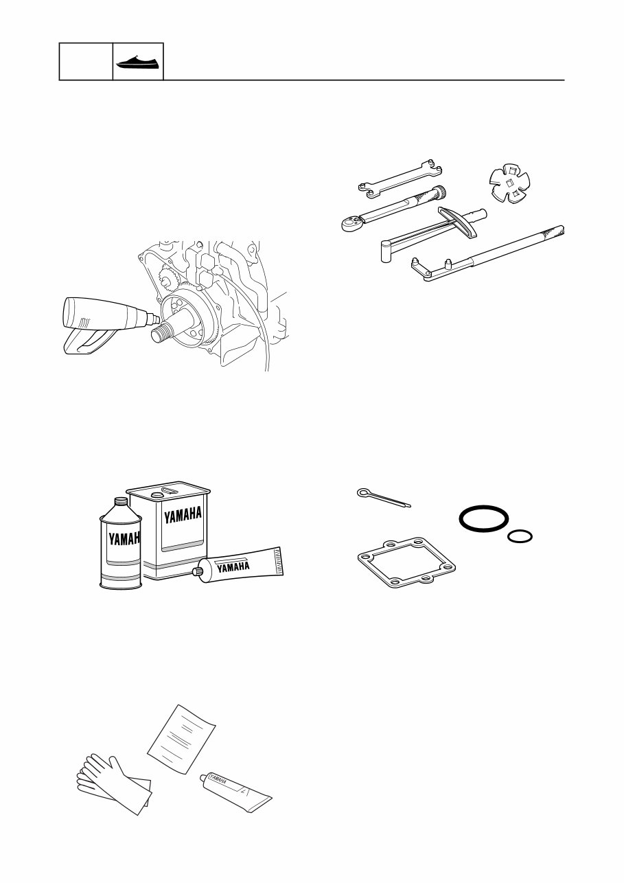
Handling of heat gun
• Improper handling of a heat gun may result
in burns. For information on the proper han-
dling of the heat gun, see the operation
manual issued by the manufacturer.
• When using a heat gun, keep it away from
the gasoline and oil, to prevent a fire.
• Components become hot enough to cause
burns. Do not touch any hot components
directly.
Part, lubricant, and sealant
Use only genuine Yamaha parts, lubricants,
and sealants, or those recommended by
Yamaha, when servicing or repairing the
watercraft.
Handling of sealant
• Wear protective gloves to protect your skin,
when using the sealants.
• See the material safety data sheet issued
by the manufacturer. Some of the sealants
may be harmful to human health.
Special service tool
Use the recommended special service tools
to work safely, and to protect parts from dam-
age.
Tightening torque
Follow the tightening torque specifications
provided throughout the manual. When tight-
ening nuts, bolts, and screws, tighten the
large sizes first, and tighten fasteners starting
in the center and moving outward.
Non-reusable part
Always use new gaskets, seals, O-rings, cot-
ter pins, and so on, when installing or assem-
bling parts.
1-4
1
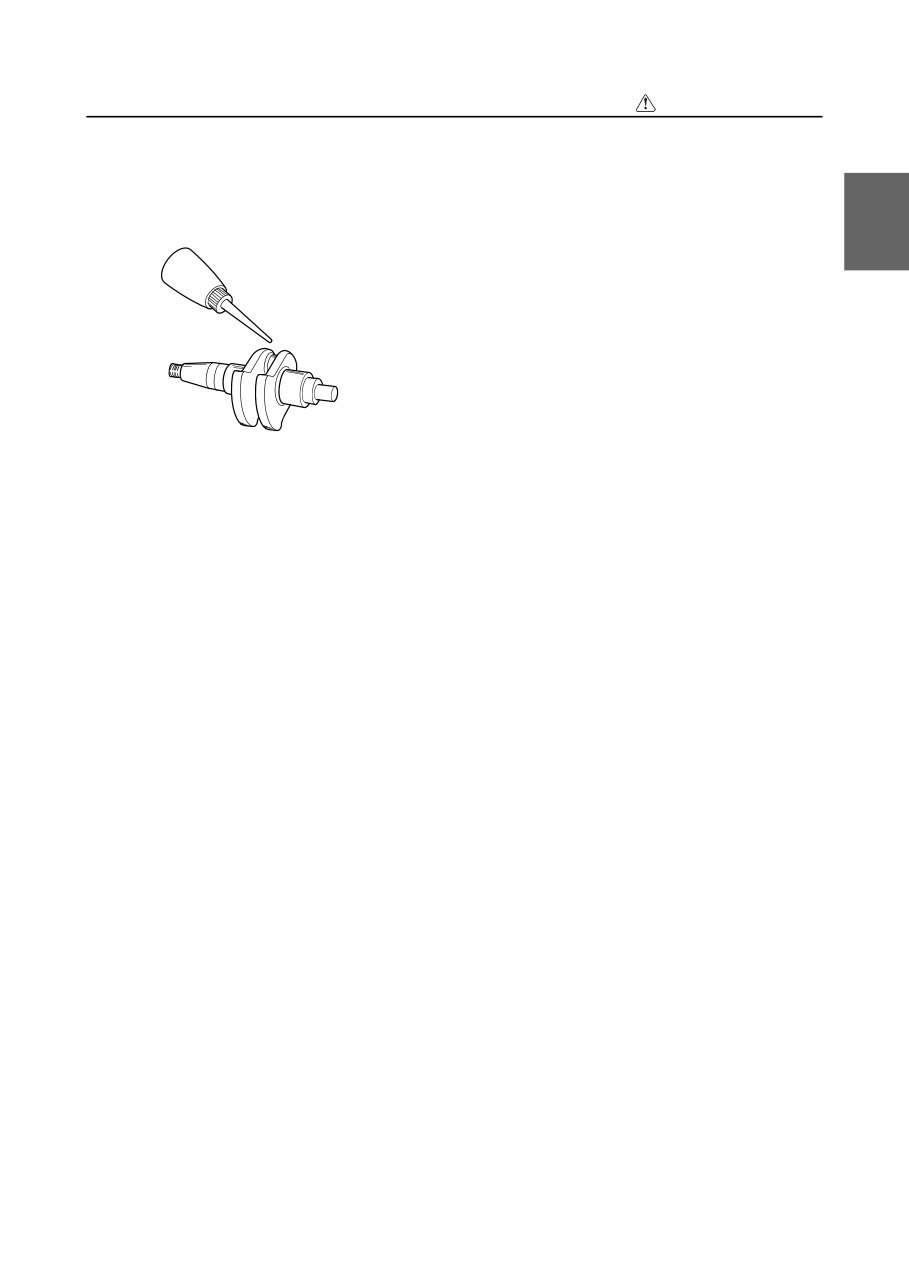
Disassembly and assembly
• Use compressed air to remove dust and dirt
during disassembly.
• Apply engine oil to the contact surfaces of
moving parts before assembly.
• Install bearings so that the bearing identifi-
cation mark is facing in the direction indi-
cated in the installation procedure. In
addition, make sure to lubricate the bear-
ings liberally.
• Apply a thin coat of water resistant grease
to the lip and periphery of an oil seal before
installation.
• Check that moving parts operate normally
after assembly.
Safety while working
1-5
GEN
INFO
General information
How to use this manual
Manual format
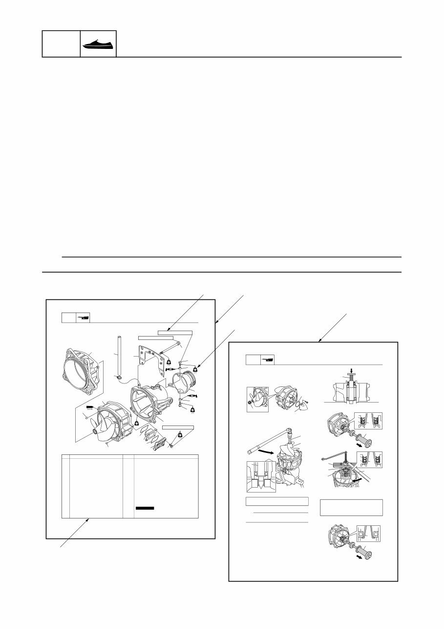
The format of this manual has been designed to make service procedures clear and easy to under-
stand. Use the information below as a guide for effective and quality service.
• Parts are shown and detailed in an exploded diagram and are listed in the component list (see 1
in the following figure for an example page).
• The component list consists of part names and quantities, as well as bolt and screw dimensions
(see 2 in the following figure). To assemble or install the components, reverse the steps indicated
in the component list.
• Symbols are used to indicate important aspects of a procedure, such as the grade of lubricant and
the lubrication point (see 3 in the following figure).
• Tightening torque specifications are provided in the exploded diagrams (see 4 in the following fig-
ure), and in the related detailed instructions. Some torque specifications are listed in stages as
torque figures or angles in degrees.
• Separate procedures and illustrations are used to explain the details of removal, checking, and
installation where necessary (see 5 in the following figure for an example page).
TIP:
For troubleshooting procedures, see Chapter 9, “Troubleshooting.”
6-7
JET
PUMP Jet pump unit
Nozzle, impeller housing, and impeller duct assy.
No. Part name Q’ty Remarks
1 p m a l C 1
1 e s o h t u o p S 2
8 M 2 t l o B 3 × 25 mm
2 r a l l o C 4
1 e l z z o n t s u r h t t e J 5
0 1 M 4 t l o B 6 × 125 mm
1 t e k c a r B 7
1 e l z z o N 8
1 g n i s u o h r e l l e p m I 9
2 n i p l e w o D 0 1
6 M 4 t l o B 1 1 × 35 mm
1 r e v o c t e l n i r e t a W 2 1
2 g n i k c a P 3 1 Not reusable
1 r e n i a r t s t e l n i r e t a W 4 1
1 . y s s a t c u d r e l l e p m I 5 1
4
3
5
8
11 10
10
9
2
1
7
6
15
12
13
14
13
4
3
7 N·m (0.7 kgf·m, 5.2 ft·Ib)
15 N·m (1.5 kgf·m, 11.1 ft·Ib)
40 N·m (4.0 kgf·m, 29.5 ft·Ib)
6-9
JET
PUMP Jet pump unit
Impeller duct assy. disassembly
1. Remove the cap 1, O-ring 2, and
impeller cap 3.
2. Remove the impeller 4.
TIP:
Hold the drive shaft 6 in a vise between two
aluminum plates a.
3. Remove the drive shaft 6 using a press.
NOTICE: Do not press the drive shaft
threads directly.
4. Remove the oil seals 7 and 8.
È U.S.A. and Canada
É Worldwide
5. Remove the rear bearing C.
Crankshaft holder 5: YB-06552
Crankshaft holder 20 5: 90890-06552
3
1
2
a
6
5
4
Slide hammer 9: YB-06096
Stopper guide plate 0: 90890-06501
Bearing puller assembly A: 90890-06535
Stopper guide stand B: 90890-06538
6
9
9
7
8
È
0
B
B
A
A
7
8
É
9
9
C
È
1
5
3
2
4
You're Reading a Preview
What's Included?
 Lifetime Access
Fast Download Speeds
Online & Offline Access
Access PDF Contents & Bookmarks
Full Search Facility
Print one or all pages of your manual
$39.99
2010-2015 Yamaha Waverunner VX Cruiser VX Deluxe VX Sport F2N VX1100 Service & Repair Manual
Viewed 83 Times Today

What's Included?
Lifetime Access
Fast Download Speeds
Online & Offline Access
Access PDF Contents & Bookmarks
Full Search Facility
Print one or all pages of your manual
$39.99

Secure transaction
What's Included?
Lifetime Access
Fast Download Speeds
Online & Offline Access
Access PDF Contents & Bookmarks
Full Search Facility
Print one or all pages of your manual
Description
- Complete Factory Service Repair Workshop Manual for Yamaha Waverunner VX Cruiser VX Deluxe VX Sport F2N VX1100 2010-2015.
- Accessible for instant download to your computer, tablet, or smartphone.
- Includes detailed photos & diagrams, covering all repairs, servicing, and troubleshooting procedures.
- Utilized by professional mechanics and technicians, featuring step-by-step instructions and highly detailed exploded diagrams & pictures.
- Printable - allows printing of single pages or the entire manual.
- Multi-Computer Use - can be used on multiple computers without limitations.
- Full Version - no trial, limitations, or expiry dates, can be used for life.
- Compatibility - fully compatible with Windows & MAC computers.
Thanks for considering this manual. Click the button to proceed.


