E HOW TO USE THIS MANUAL MANUAL FORMAT All of the procedures in this manual are organized in a sequential, step-by-step format. The informa- tion has been compiled to provide the mechanic with an easy to read, handy reference that contains comprehensive explanations of all disassembly, repair, assembly, and inspection operations. In this revised format, the condition of a faulty component will precede an arrow symbol and the course of action required will follow the symbol, e.g., • Bearings Pitting/scratches → Replace. To assist you in finding your way through this manual, the section title and major heading is given at the top of every page. ILLUSTRATIONS The illustrations within this service manual represent all of the designated models. CROSS REFERENCES The cross references have been kept to a minimum. Cross references will direct you to the appropri- ate section or chapter. Downloaded from www.Manualslib.com manuals search engine
E IMPORTANT INFORMATION In this Service Manual particularly important information is distinguished in the following ways. The Safety Alert Symbol means ATTENTION! BECOME ALERT! YOUR SAFETY IS INVOLVED! WARNING Failure to follow WARNING instructions could result in severe injury or death to the machine operator, passenger(s), a bystander, or a person inspecting or repairing the watercraft. CAUTION: A CAUTION indicates special precautions that must be taken to avoid damage to the water- craft. NOTE: A NOTE provides key information to make procedures easier or clearer. IMPORTANT: This part has been subjected to change of specification during production. Downloaded from www.Manualslib.com manuals search engine
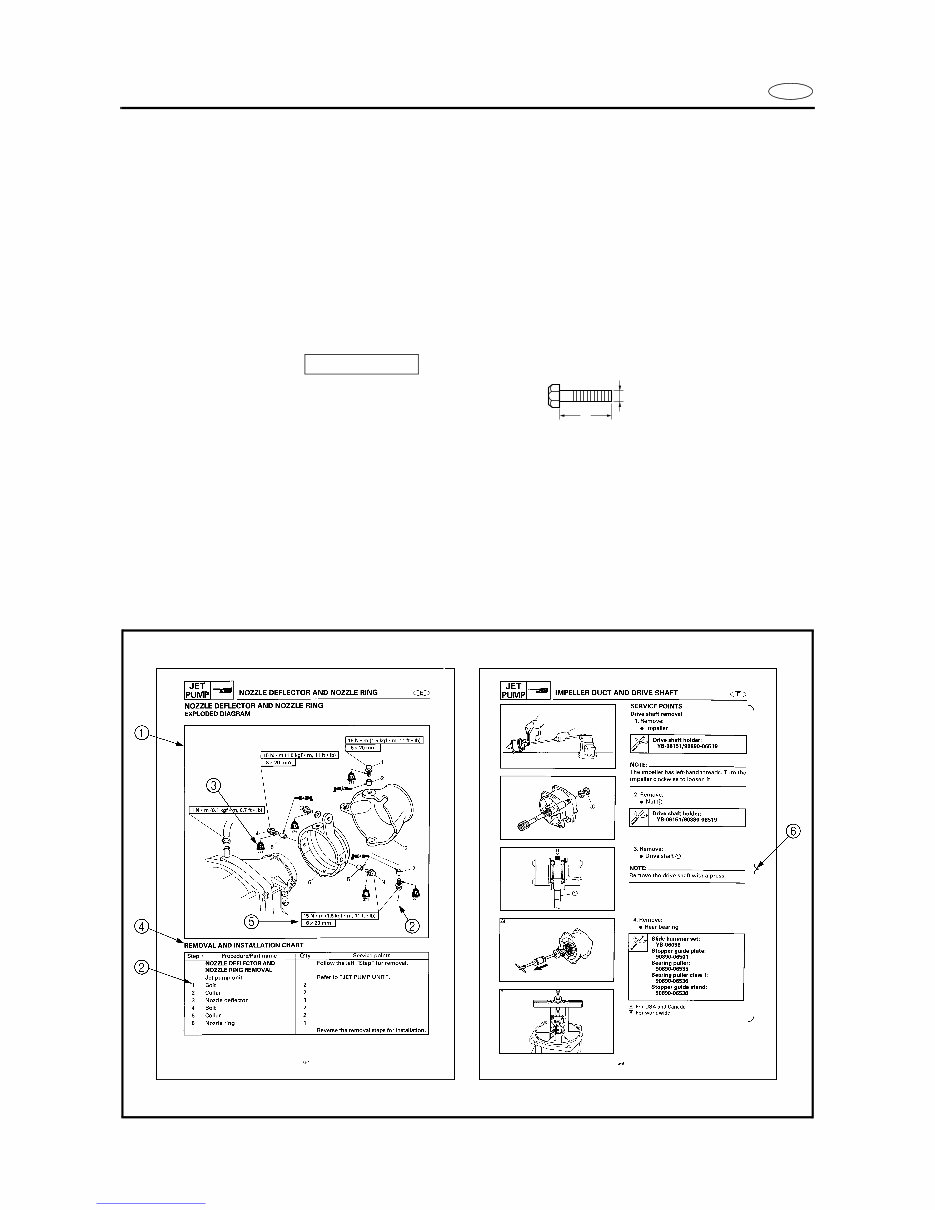
E HOW TO USE THIS MANUAL 1 To help identify parts and clarify procedure steps, there are exploded diagrams at the start of each removal and disassembly section. 2 Numbers are given in the order of the jobs in the exploded diagram. 3 Symbols indicate parts to be lubricated or replaced (see “SYMBOLS”). 4 A job instruction chart accompanies the exploded diagram, providing the order of jobs, names of parts, notes in jobs, etc. 5 Dimension figures and the number of parts, are provided for fasteners that require a tightening torque. Example: Bolt or screw size : M10 (D) × 25 mm (L) 6 Jobs requiring more information (such as special tools and technical data) are described sequentially. 10 × 25 mm D L Downloaded from www.Manualslib.com manuals search engine
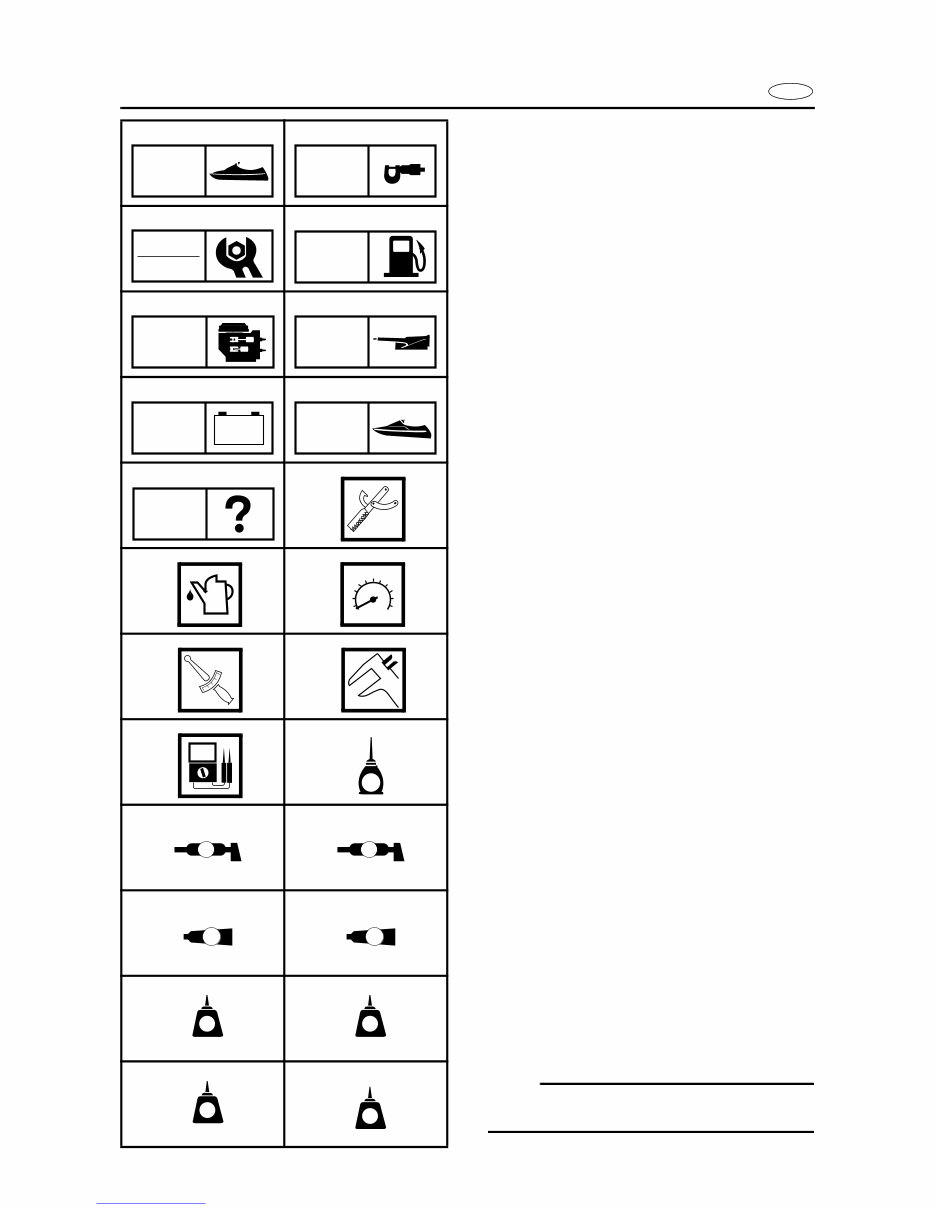
E A50001-1-4 SYMBOLS Symbols 1 to 9 are designed as thumb-tabs to indicate the content of a chapter. 1 General Information 2 Specifications 3 Periodic Inspection and Adjustment 4 Fuel System 5 Power Unit 6 Jet Pump Unit 7 Electrical System 8 Hull and Hood 9 Trouble analysis Symbols 0 to E indicate specific data: 0 Special tool A Specified liquid B Specified engine speed C Specified torque D Specified measurement E Specified electrical value [Resistance (Ω), Voltage (V), Electric current (A)] Symbol F to H in an exploded diagram indi- cate the grade of lubricant and the location of lubrication point: F Apply YAMALUBE 4-stroke motor oil G Apply water resistant grease (Yamaha grease A, Yamaha marine grease) H Apply molybdenum disulfide grease Symbols I to N in an exploded diagram indi- cate the grade of the sealing or locking agent, and the location of the application point: I Apply Gasket Maker ® J Apply Yamabond #4 (Yamaha bond number 4) K Apply LOCTITE ® No. 271 (Red LOCTITE) L Apply LOCTITE ® No. 242 (Blue LOCTITE) M Apply LOCTITE ® No. 572 N Apply silicone sealant NOTE: In this manual, the above symbols may not be used in every case. 1 2 3 4 5 6 7 8 9 0 A B C D E F G H I J K L M N GEN INFO SPEC INSP ADJ FUEL POWR JET PUMP – + ELEC HULL HOOD TRBL ANLS T R . . E A M GM 4 271 LT 242 LT 572 LT SS Downloaded from www.Manualslib.com manuals search engine
E INDEX GENERAL INFORMATION 1 GEN INFO SPECIFICATIONS 2 SPEC PERIODIC INSPECTION AND ADJUSTMENT 3 INSP ADJ FUEL SYSTEM 4 FUEL POWER UNIT 5 POWR JET PUMP UNIT 6 JET PUMP ELECTRICAL SYSTEM 7 ELEC HULL AND HOOD 8 HULL HOOD TROUBLE ANALYSIS 9 TRBL ANLS – + A30000-0 Downloaded from www.Manualslib.com manuals search engine
Downloaded from www.Manualslib.com manuals search engine
E GEN INFO 1 2 3 4 5 6 7 8 9 CHAPTER 1 GENERAL INFORMATION IDENTIFICATION NUMBERS ......................................................................... 1-1 PRIMARY l.D. NUMBER ........................................................................... 1-1 ENGINE SERIAL NUMBER ...................................................................... 1-1 JET PUMP UNIT SERIAL NUMBER ......................................................... 1-1 HULL IDENTIFICATION NUMBER (H.l.N.) ............................................... 1-1 SAFETY WHILE WORKING...................................................................... 1-2 FIRE PREVENTION .................................................................................. 1-2 VENTILATION ........................................................................................... 1-2 SELF-PROTECTION ................................................................................. 1-2 OILS, GREASES AND SEALING FLUIDS ................................................ 1-2 GOOD WORKING PRACTICES ............................................................... 1-3 DISASSEMBLY AND ASSEMBLY ............................................................ 1-4 SPECIAL TOOLS ............................................................................................ 1-5 MEASURING ............................................................................................. 1-5 REMOVAL AND INSTALLATION .............................................................. 1-8 Downloaded from www.Manualslib.com manuals search engine
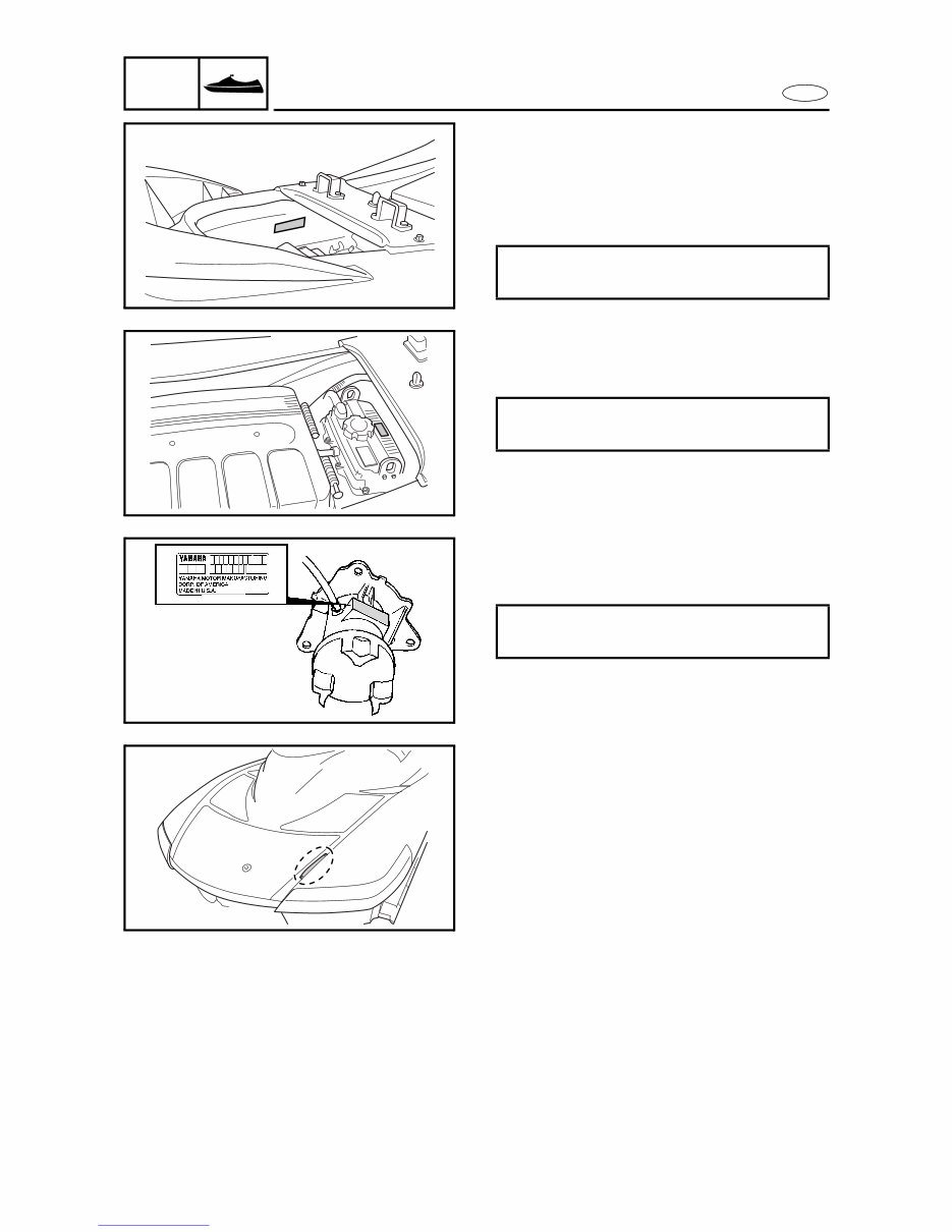
1-1 E GEN INFO IDENTIFICATION NUMBERS A60700-0* IDENTIFICATION NUMBERS PRIMARY l.D. NUMBER The primary l.D. number is stamped on a label attached to the inside of the engine compart- ment. Starting primary l.D. number: F1B: 800101 ENGINE SERIAL NUMBER The engine serial number is stamped on a label attached to the engine unit. Starting serial number: 60E: 000101 JET PUMP UNIT SERIAL NUMBER The jet pump unit serial number is stamped on a label attached to the intermediate housing. Starting serial number: 60E: 800058 HULL IDENTIFICATION NUMBER (H.l.N.) The H.l.N. is stamped on a plate attached to the aft deck. Downloaded from www.Manualslib.com manuals search engine
Get instant access to the Complete Factory Service Repair Workshop Manual without any extra fees or expiry dates. This Professional Manual is suitable for your computer, tablet, or smartphone and covers all repairs, servicing, and troubleshooting procedures. It contains hundreds of pages with detailed photos and diagrams, along with step-by-step instructions and highly detailed exploded diagrams and pictures used by professional Mechanics and Technicians. You have the flexibility to print out a single page or the entire manual as per your requirement. Additionally, this FULL Manual without any limitations or trial periods can be used for life on multiple computers without the need for renewal or extra payment. It is fully compatible with Windows and MAC computers. Click the button to access this comprehensive manual.
Recently Viewed
5,521,897Happy Clients
2,594,462eManuals
1,120,453Trusted Sellers
15Years in Business
Price:
Actual Price:
YAMAHA WAVERUNNER FX140 FX140 CRUISER PWC Full Service & Repair Manual 2002-Onwards