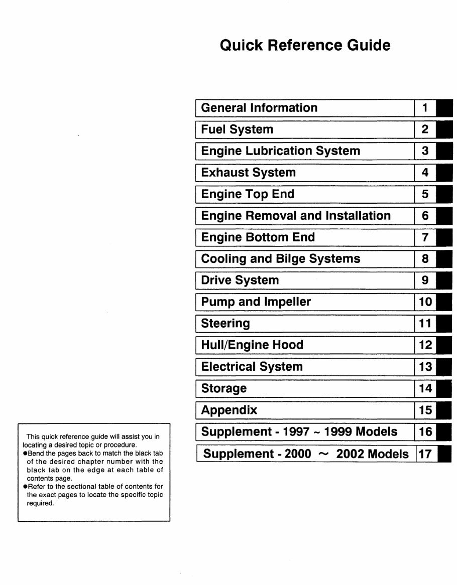
This quick reference guide will assist you in locating a desired topic or procedure. eSend the pages back to match the black tab of the desired chapter number with the black tab on the edge at each table of contents page. eRefer to the sectional table of contents for the exact pages to locate the specific topic required. Quick Reference Guide General Information Fuel System Engine Lubrication System Exhaust System Engine Top End Engine Removal and Installation Engine Bottom End Cooling and Bilge Systems Drive System Pump and Impeller Steering Hull/Engine Hood Electrical System Storage Appendix Supplement - 1997 - 1999 Models Supplement - 2000 '" 2002 Models
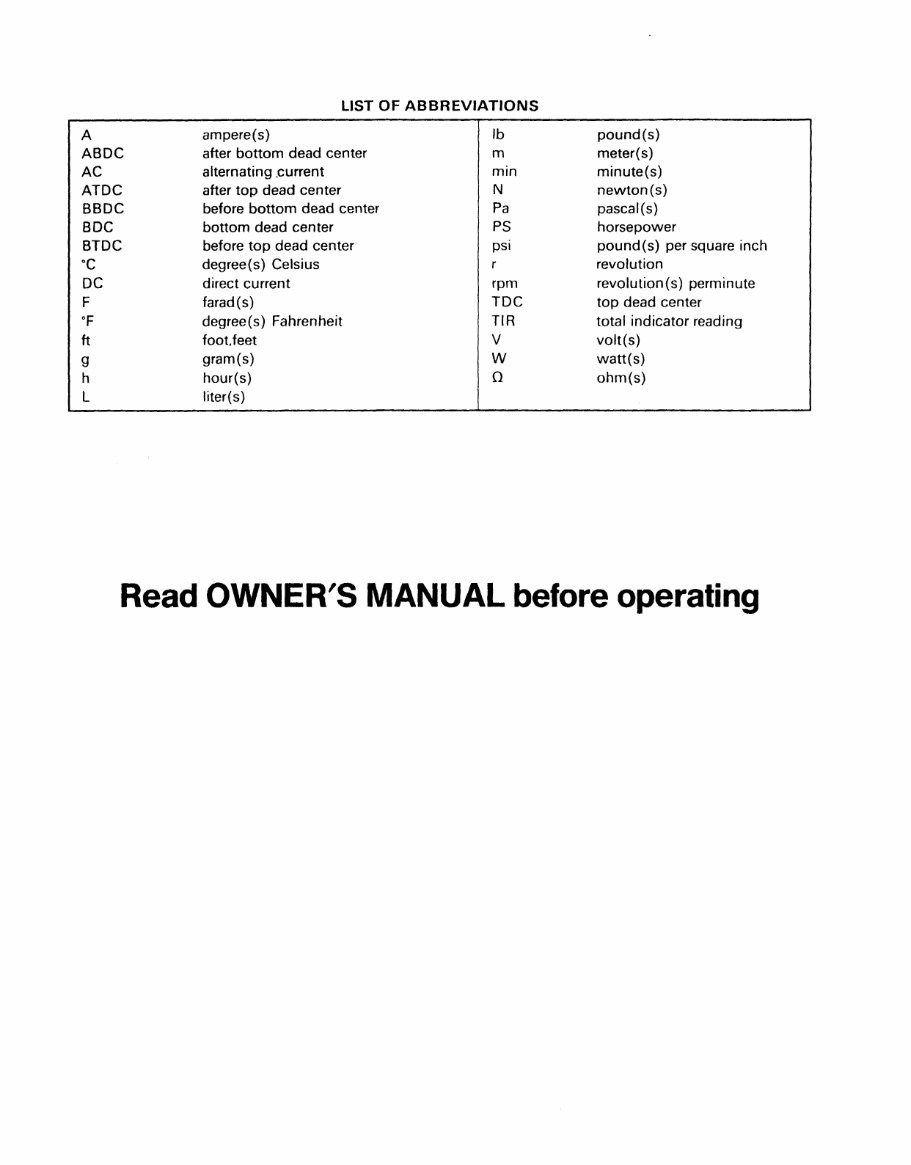
LIST OF ABBREVIATIONS A ampere(s) Ib pound(s) ABDC after bottom dead center m meter(s) AC alternating .current min minute(s) ATDC after top dead center N newton(s) BBDC before bottom dead center Pa pascal(s) BDC bottom dead center PS horsepower BTDC before top dead center psi pound(s) per square inch °C degree(s) Celsius revolution DC direct current rpm revolution(s) perminute F farad(s) TDC top dead center of degree(s) Fahrenheit TIR total indicator reading ft footfeet V volt(s) 9 gram(s) W watt(s) h hour(s) 0 ohm(s) L liter( s) Read OWNER'S MANUAL before operating
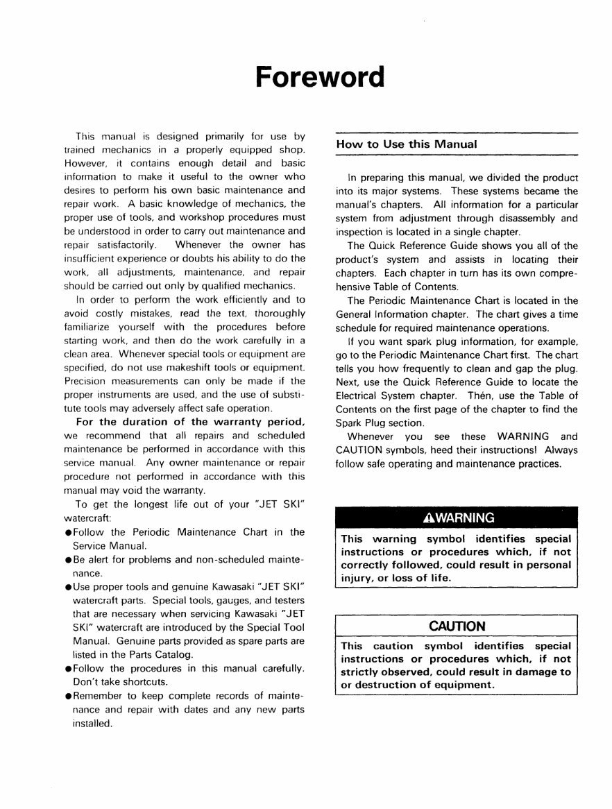
Foreword This manual is designed primarily for use by trained mechanics in a properly equipped shop. However, it contains enough detail and basic information to make it useful to the owner who desires to perform his own basic maintenance and repair work. A basic knowledge of mechanics, the proper use of tools, and workshop procedures must be understood in order to carry out maintenance and repair satisfactorily. Whenever the owner has insufficient experience or doubts his ability to do the work, all adjustments, maintenance, and repair should be carried out only by qualified mechanics. In order to perform the work efficiently and to avoid costly mistakes, read the text thoroughly familiarize yourself with the procedures before starting work, and then do the work carefully in a clean area. Whenever special tools or equipment are specified, do not use makeshift tools or equipment. Precision measurements can only be made if the proper instruments are used, and the use of substi- tute tools may adversely affect safe operation. For the duration of the warranty period, we recommend that all repairs and scheduled maintenance be performed in accordance with this service manual. Any owner maintenance or repair procedure not performed in accordance with this manual may void the warranty. To get the longest life out of your "JET SKI" watercraft: • Follow the Periodic Maintenance Chart in the Service Manual. • Be alert for problems and non-scheduled mainte- nance. • Use proper tools and genuine Kawasaki "JET SKI" watercroft parts. Special tools, gauges, and testers that are necessary when servicing Kawasaki "J ET SKI" watercraft are introduced by the Special Tool Manual. Genuine parts provided as spare parts are listed in the Parts Catalog. .Follow the procedures in this manual carefully. Don't take shortcuts. • Remember to keep complete records of mainte- nance and repair with dates and any new parts installed. How to Use this Manual In preparing this manual, we divided the product into its major systems. These systems became the manual's chapters. All information for a particular system from adjustment through disassembly and inspection is located in a single chapter. The Quick Reference Guide shows you all of the product's system and assists in locating their chapters. Each chapter in turn has its own compre- hensive Table of Contents. The Periodic Maintenance Chart is located in the General Information chapter. The chart gives a time schedule for required maintenance operations. If you want spark plug information, for example, go to the Periodic Maintenance Chart first. The chart tells you how frequently to clean and gap the plug. Next use the Quick Reference Guide to locate the Electrical System chapter. Then, use the Table of Contents on the first page of the chapter to find the Spark Plug section. Whenever you see these WARNING and CAUTION symbols, heed their instructions! Always follow safe operating and maintenance practices. AWARNING This warning symbol identifies special instructions or procedures which, if not correctly followed, could result in personal injury, or loss of life . CAUTION This caution symbol identifies special instructions or procedures which, if not strictly observed, could result in damage to or destruction of equipment.
This manual contains four more symbols (in addition to WARNING and CAUTION) which will help you distinguish different types of information. NOTE o This note symbol indicates points of partic- ular interest for more efficient and convenient operation . • Indicates a procedural step or work to be done. o Indicates a procedural sub-step or how to do the work of the procedural step it follows. It also precedes the text of a NOTE. * Indicates a conditional step or what action to take based on the results of the test or inspection in the procedural step or sub-step it follows. In most chapters an exploded view illustration of the system components follows the Table of Contents. In these illustrations you will find the instructions indicating which parts require specified tighte~ing torque, oil, grease or a locking agent during assembly.
GENERAL INFORMATION 1-1 General Information Table of Contents Before Servicing ............................................................................................................ 1-2 Model Identification .................................................................................................... 1-5 General Specifications .................................................................................................. 1-6 Torque and locking Agent ......................................................................................... 1 -7 Periodic Maintenance Chart .......................................................................................1-9 Technical Information ............................................................................................... 1-10 Maintenance Free Battery .....................................................................................1 -10 (I) Construction .................................................................................................. 1 -1 0 (n) Main Features ............................................................................................ 1-10 (III) Principle of Sealing Structure .................................................................... 1-10 (IV) Filling the Battery with Electrolyte ...........................................................1-11 (V) Initial Charge ............................................................................................... 1-12 (VI) Precautions ............................................................................................... 1-13 Accelera~or Pump ................................................................................................. 1 -14 Kawasaki Air Induction System (KAIS) ............................................................... 1·15 Kawasaki Automatic Trim System (KATS) ..........................................................1 -16 Special Too'ls, Sealant ............................................................................................... 1 -17 Cable, Wire and Hose Routing ..................................................................................1 ·19
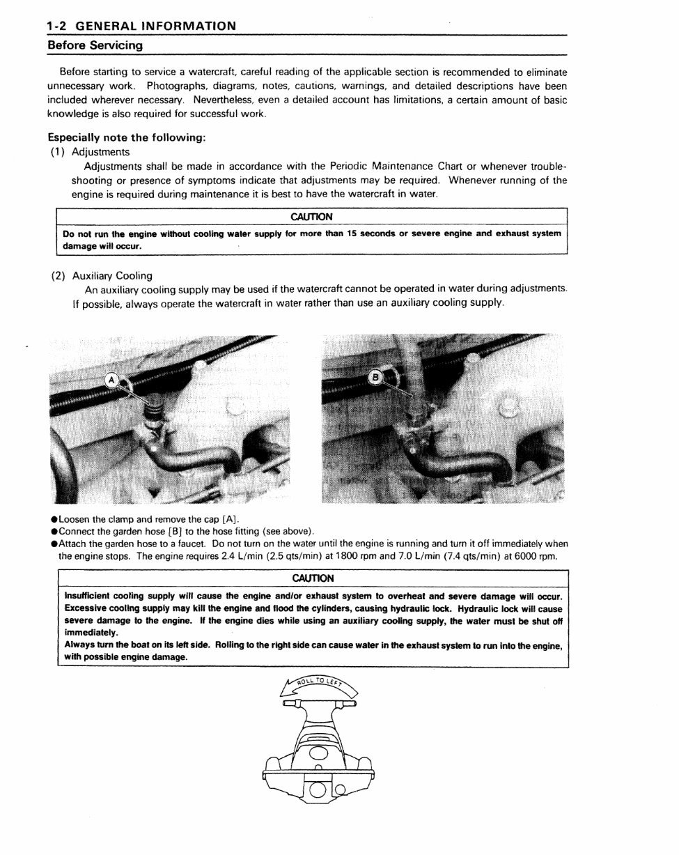
1-2 GENERAL INFORMATION Before Servicing Before starting to service a watercraft careful reading of the applicable section is recommended to eliminate unnecessary work. Photographs, diagrams, notes, cautions, warnings, and detailed descriptions have been included wherever necessary. Nev,ertheless, even a detailed account has limitations, a certain amount of basic knowledge is also required for successful work. Especially note the following: (1) Adjustments Adjustments shall be made in accordance with the Periodic Maintenance Chart or whenever trouble- shooting or presence of symptoms indicate that adjustments may be required. Whenever running, of the engine is required during maintenance it is best to have the watercraft in water. CAUTION Do not. run 1he engine without cooling waler supply lor more Hlan15 seconds or severe engine and exhaust system damag!e will occur .. (2) Auxiliary Cooling An auxiliary cooling supply may be used if the watercraft cannot be operated in water during adjustments. If possible, always operate the watercraft in water rather than use an auxiliary cooling supply . • loosen the clamp and remove the cap [A.) . • Connect the garden hose [BJ to the hose fitting (see above) . • Attach the garden hose to a faucet. Do not turn on the water until the engine is running and turn 'it off immediately when the engine stops. The engine requires 2.4 l/min (2 .. 5 qts!min) at 1800 rpm and 7.0 l/min (7.4 qts!min) at 6000 rpm. CAUTION Insufficient COOling supply will cause the engine andlor e.xhaust system to overheat and severe damage will occur. Excessive cooling. supply may kill the engine and flood the cylinders., causing hydraulic lock. 'Hydraulic lock will cause severe damage 10' the engine. If the engine dies while using anauxUiary cooling supp,ly, the water must be shut off immediately. Always turn the boat on its left side. Rolling. to the right side can cause water in the exha.ustsyslem to run into the engine, t wilh possible engine damage.
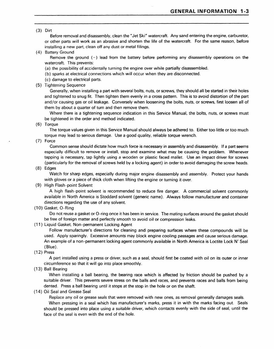
GENERAL INFORMATION 1-3 (3) Dirt Before removal and disassembly, clean the "Jet Ski" watercraft. Any sand entering the engine, carburetor, or other parts will work as an abrasive and shorten the life of the watercraft. For the same reason, before installing a new part, clean off any dust or metal filings. (4) Battery Ground Remov1e the ground (-) lead from the battery before performing any disassembly operations on the watercraft. This prevents: (a) the possibility of acciidentally turning the engine over while partially disassembled. (b) sparks at electrical connections which will occur when they are disconnected. (c) damage to electrical parts. (5) Tightening Sequence Generally, when instaUing a part with severali bolts, nuts, or screws, they should all be started in the'ir holes and tightened to snug fit. Then tighten them evenly in a cross pattern. This is to avoid distortion of the part and/or causing gas or oiil leakage. Conversely when loosening the bolts, nuts, or screws,. first loosen all of them by about a quarter of turn and then remove them. Where there is a tightening sequence indication in this Service Manual, the bolts, nuts, or screws must be tight1ened in the order and method indicated. (6) Torque The torque values given in this Service Manual should always be adhered to. Either too little or too much torque may lead to serious damage. Use a good quality, rel.iable torque wrench. (7) Force Common sense should dictate how much fame is necessary in assembly and disassembly. If a part seems especially difficult to remove orinst.all. s.top and examine what may be causing the problem. Whenever tapping is necessary, tap lightly using a wooden or plastic faced mallet. Use an impact driver for screws (particularly for the removal of screws held by a locking agent) in order to avoid damaging the screw heads. (8) Edges Watch for sharp edges, especially during major engine disassembly and assembly. Protect your hands with gloves or a piece of thick cloth when lifting the engine or turning it over. (9) High Flash-point Solvent A high Hash-point solvent is recommended to reduce fire danger. A commercial solvent commonly available in North America is Stoddard solvent (generic name). Always follow manufacturer and container directions regarding the use of any solvent. (10) Gasket 0- Ring Do not reuse a gasket or 0- ring once it has been in service. The mating. surfaces around the gasket should be hee of foreign matter and perfectly smooth to avoid oil or compression leaks. (11) Liquid Gasket Non-permanent Locking Aglent Follow manufacturer's directions for cleaning and preparing surfaces where these compounds will be used. Apply sparingly. Excessive amounts may block engine cooling passages and cause serious damage. An example of a non-permanent locking agent commonliy available in North America! is Loctite Lock N' Seal (Blue). (12) Press A part installed using a press or driver, such as a seal, should first be coated with oil on its outer or inner circumference so that it will go into place smoothly. (13) Ball Bearing When installing a ball bearing, the beari!ng raoe which is affected by friction should be pushed by a suitable driver .. This prevents severe stress on the balls and races, and prevents races and baUs from being dented. Press a ball bearing until it stops at the stop in the hole or on the shaft. (14); Oil Seal and Grease Seal Replace any oi,l or grease seals that were removed with new ones, as removal generally damages seals. When pressing in a seal which has manufacturer's marks, press it in with the marks facing out. Seals should be pressed into place using a suitable driver, which contacts evenly with the side of seal., until the face of the seal is even with the end of the hole.
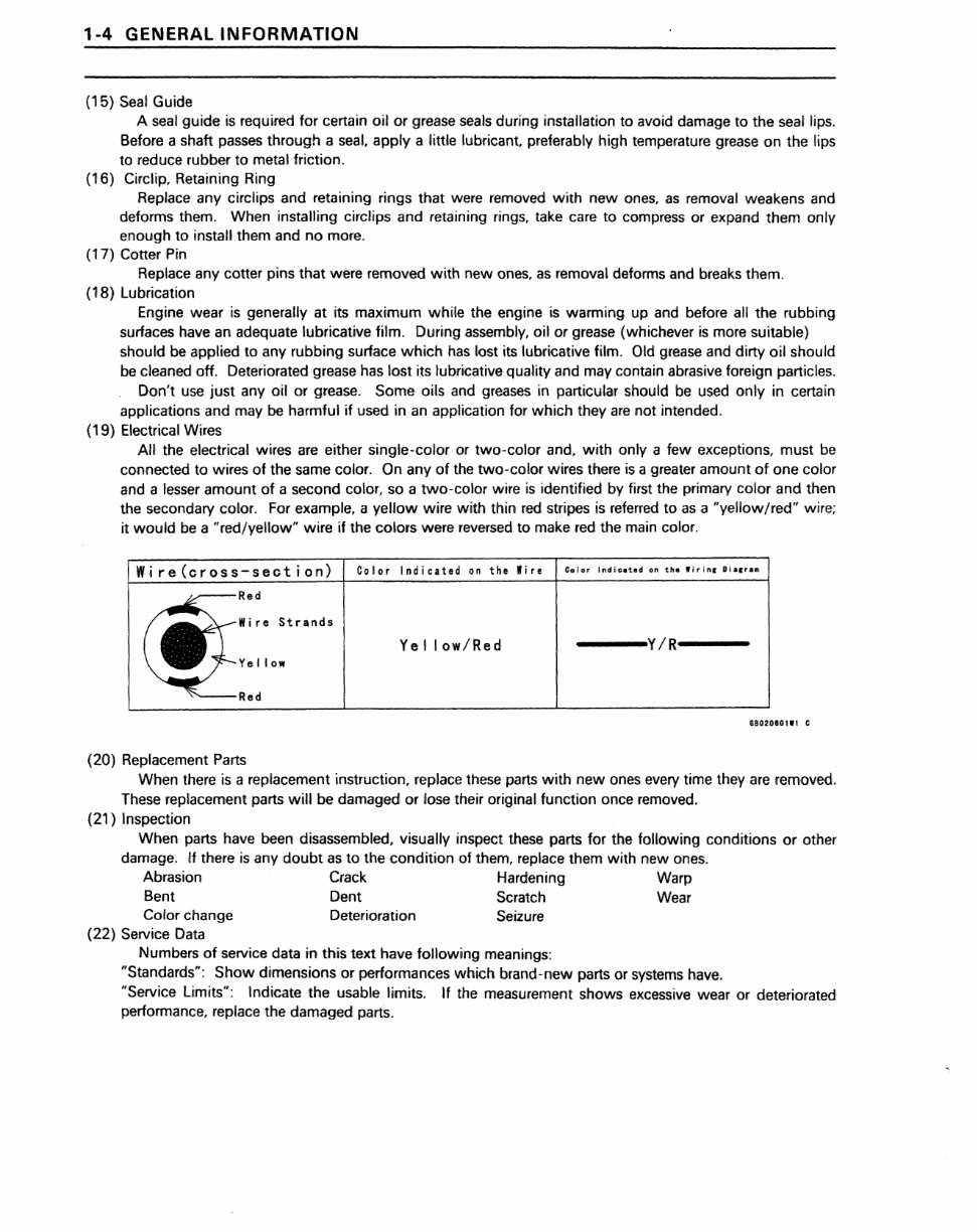
1-4 GENE'RAL INFORMATION (15) Seal Guide A seal guide is required for certain o.il or grease seals during installation to avoid damage to the seal lips. Before a shaft passes through a seal. apply a little lubricant. preferably high temperature grease on the lips to reduce rubber to metal friction. (16) Circlip, Retaining Ring Replace .any circ'lips and retaining rings that were removed with new ones, as removal weakens and deforms them. When installing circl.ipsand retaining rings, take care to compress or expand them only enough to install them and no more. (17) Cotter Pin Replace any cotter pins that were removed with new ones, as removal deforms and breaks them. (18) Lubrication Engine wear is g.enerally at its maximum while the engine is warming up and before all the rubbing surfaces have an adequate lubricative film. During assembly, oil or grease (whichever is more suitable) should be applied to any rubbing surface which has lost its lubricative film. Old grease and dirty oil should be cleaned off. Deteriorated grease has lost its lubricative quality and may contain abrasive foreign particles. Don't use just any oil or grease. Some oils and greases in particular should be used only in certain applications and may be harmful if used in an application for which they are not intended. (19) Electrical Wires All the electrical wires are either single-color or two-color and. with only a few exceptions. must be connected to wires of the same COIOf. On any of the two-cotor wires there is a greater amount of one color and a lesser amount of a second color, so a two-color wire is identified by first the primary color and then the secondary color. For example. a yellow wiire w,ith thin red stripes is referred to as a "yeHow!red" wire; it would be a "red/yellow" wire if the colors were reversed to make red the main color. Wire(cross-section) Co.lor Indicated on the· Wire C.lo, Ind;,eo,hd on tho W;,;ng O;a,ru /~--Red Wi re Stra.nds Yellow/Hed ---Y/R--- Ve II ow '''---Red 6102080111 C (20) Replacement Parts When there is a replacement instruction, replace these parts with new ones every time they are removed. These replacement parts will be damaged or lose their original function once removed. (21) Inspection When parts have been disassembled, visually inspect these parts for the following conditions or other damage. ,If there is any doubt as to the condition of them, replace them with new ones .. Abrasion Crack Hardening Warp Bent Dent Scratch Wear Color change (22) Service Data Deterioration Seizur.e Numbers of service data in this text have following meanings: "Standards":. Show dimensions or performances which brand-new parts or systems have. "Service Limits": Indicate the usable limits. If the measurement shows excessive wear or deteriorated performance. replace the damaged parts.
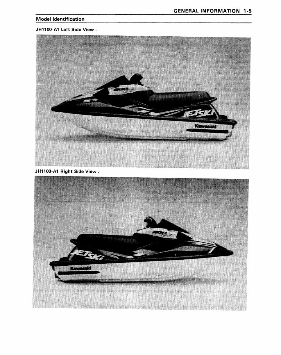
GENERAL INFORMATION 1-'5 Modelldentifi,cation JH1100-A1 left Side View: JH1100-A1 Right S,ide View:
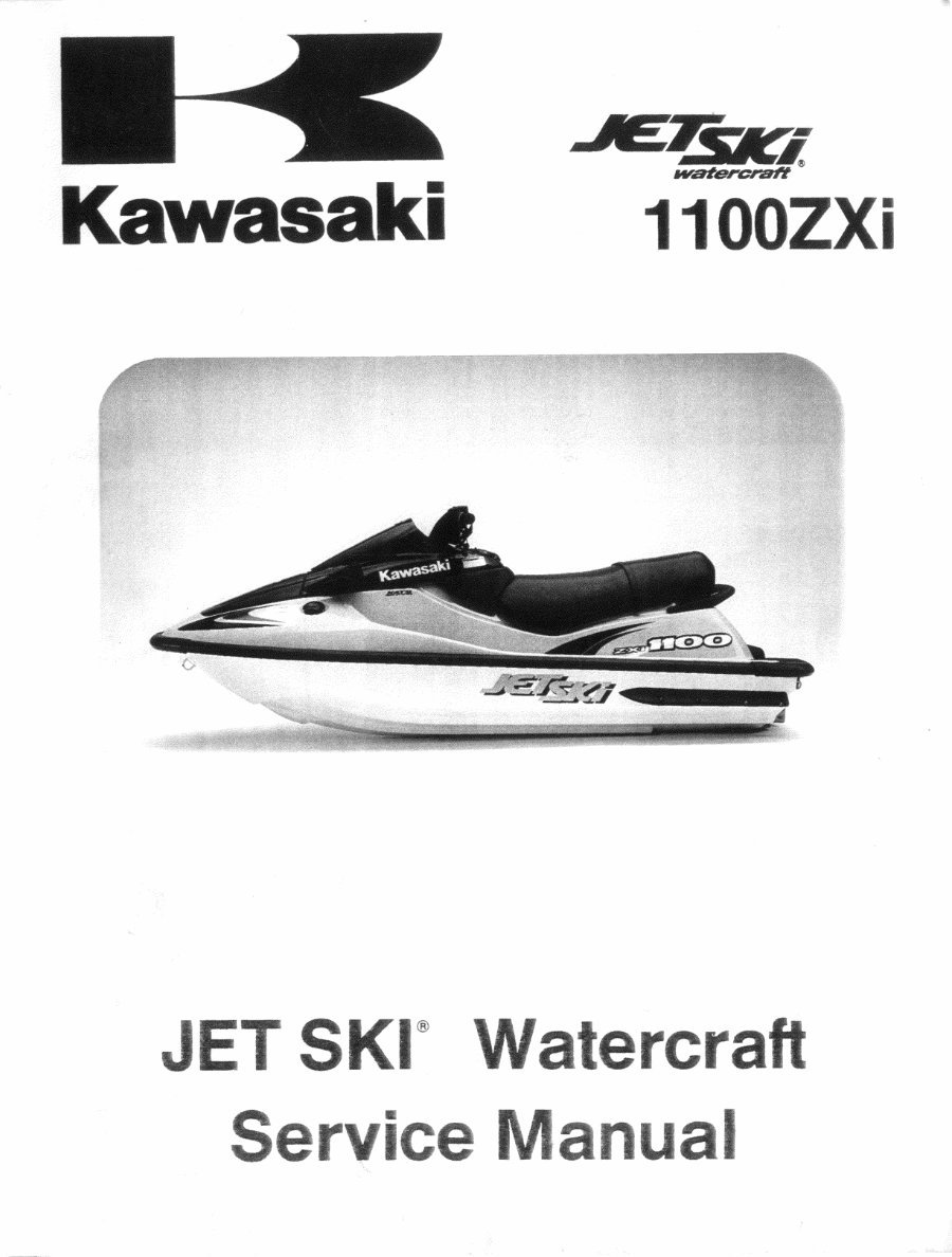
This Service Repair Manual is a comprehensive guide for the Kawasaki JetSki Watercraft 1100ZXI from 1996 to 2002. It includes high-quality diagrams and detailed instructions covering the entire watercraft, making it essential for both professional mechanics and DIY enthusiasts.
The manual covers a wide range of topics including General Information, Fuel System, Engine Lubrication System, Exhaust System, Engine Top End, Engine Removal And Installation, Engine Bottom End, Cooling System, Drive System, Pump And Impeller, Steering, Hull/Engine Hood, Electrical System, Storage, Appendix, and Supplements for specific models and years.
With this manual, you can save on postage and packaging as it is available for instant download. It is compatible with all versions of Windows and Mac, and can be viewed using Adobe Reader.



 Lifetime Access




