

KAWASAKI JET SKI ULTRA 150 JH1200 PWC Full Service & Repair Manual 2003-2005
What's Included?
Fast Download Speeds
Online & Offline Access
Access PDF Contents & Bookmarks
Full Search Facility
Print one or all pages of your manual
ULTRA150
JET SKI
®
Watercraft
Service Manual
This quick reference guide will assist
you in locating a desired topic or pro-
cedure.
•Bend the pages back to match the
black tab of the desired chapter num-
ber with the black tab on the edge at
each table of contents page.
•Refer to the sectional table of contents
for the exact pages to locate the spe-
cific topic required.
Quick Reference Guide
General Information 1
Periodic Maintenance 2
Fuel System 3
Engine Lubrication System 4
Exhaust System 5
Engine Top End 6
Engine Removal/Installation 7
Engine Bottom End 8
Cooling and Bilge System 9
Drive System 10
Pump and Impeller 11
Steering 12
Hull/Engine Hood 13
Electrical System 14
Storage 15
Appendix 16

LIST OF ABBREVIATIONS
A ampere(s) lb pound(s)
ABDC after bottom dead center m meter(s)
AC alternating current min minute(s)
ATDC after top dead center N newton(s)
BBDC before bottom dead center Pa pascal(s)
BDC bottom dead center PS horsepower
BTDC before top dead center psi pound(s) per square inch
°C degree(s) Celsius r revolution
DC direct current rpm revolution(s) perminute
F farad(s) TDC top dead center
°F degree(s) Fahrenheit TIR total indicator reading
ft foot, feet V volt(s)
g gram(s) W watt(s)
h hour(s) Ω ohm(s)
L liter(s)
Read OWNER’S MANUAL before operating.
MAINTENANCE AND ADJUSTMENTS
Maintenance, replacement, or repair of the emission control devices and systems may
be performed by any marine Sl engine repair establishment or individual.
EMISSION CONTROL INFORMATION
Fuel Information
THIS ENGINE IS CERTIFIED TO OPERATE ON UNLEADED REGULAR GRADE GASOLINE
ONLY.
A minimum of 87 octane of the antifknock index is recommended. The antiknock index is
posted on service station pumps.
Emission Control Information
To protect the environment in which we all live, Kawasaki has incorporated an exhaust emis-
sion control system in compliance with applicable regulations of the United States Environmental
Protection Agency.
Exhaust Emission Control System
This system reduces the amount of pollutants discharged into the atmosphere by the exhaust
of this engine. The fuel, ignition and exhaust systems of this engine have been carefully de-
signed and constructed to ensure an efficient engine with low exhaust pollutant levels.
Maintenance
Proper maintenance and repair are necessary to ensure that watercraft will continue to have
low emission levels. This Service Manual contains those maintenance and repair recommenda-
tions for this engine. Those items identified by the Periodic Maintenance Chart are necessary
to ensure compliance with the applicable standards.
Tampering with Emission Control System Prohibited
Federal law prohibits the following acts or the causing thereof: (1) the removal or rendering
inoperative by any person other than for purposes of maintenance, repair, or replacement, of
any device or element of design incorporated into any new engine for the purposes of emission
control prior to its sale or delivery to the ultimate purchaser or while it is in use, or (2) the use
of the engine after such device or element of design has been removed or rendered inoperative
by any person.
Among those acts presumed to constitute tampering are the acts listed below:
Do not tamper with the original emission related parts.
* CDI Ignition System
* Flame Arrester
* Fuel Filter Screen
* Spark Plugs
* Carburetor and internal parts
Foreword
This manual is designed primarily for use by
trained mechanics in a properly equipped shop.
However, it contains enough detail and basic in-
formation to make it useful to the owner who de-
sires to perform his own basic maintenance and
repair work. A basic knowledge of mechanics,
the proper use of tools, and workshop proce-
dures must be understood in order to carry out
maintenance and repair satisfactorily. When-
ever the owner has insufficient experience or
doubts his ability to do the work, all adjust-
ments, maintenance, and repair should be car-
ried out only by qualified mechanics.
In order to perform the work efficiently and
to avoid costly mistakes, read the text, thor-
oughly familiarize yourself with the procedures
before starting work, and then do the work care-
fully in a clean area. Whenever special tools or
equipment are specified, do not use makeshift
tools or equipment. Precision measurements
can only be made if the proper instruments are
used, and the use of substitute tools may ad-
versely affect safe operation.
For the duration of the warranty period,
we recommend that all repairs and scheduled
maintenance be performed in accordance with
this service manual. Any owner maintenance or
repair procedure not performed in accordance
with this manual may void the warranty.
To get the longest life out of your "JET SKI"
watercraft:
•
Follow the Periodic Maintenance Chart in the
Service Manual.
•
Be alert for problems and non-scheduled
maintenance.
•
Use proper tools and genuine Kawasaki "JET
SKI" watercraft parts. Special tools, gauges,
and testers that are necessary when servicing
Kawasaki "JET SKI" watercraft are introduced
by the Special Tool Manual. Genuine parts
provided as spare parts are listed in the Parts
Catalog.
•
Follow the procedures in this manual care-
fully. Don’t take shortcuts.
•
Remember to keep complete records of main-
tenance and repair with dates and any new
parts installed.
How to Use This Manual
In this manual, the product is divided into
its major systems and these systems make up
the manual’s chapters. The Quick Reference
Guide shows you all of the product’s system
and assists in locating their chapters. Each
chapter in turn has its own comprehensive Ta-
ble of Contents.
For example, if you want ignition coil informa-
tion, use the Quick Reference Guide to locate
the Electrical System chapter. Then, use the
Table of Contents on the first page of the chap-
ter to find the Ignition Coil section.
Whenever you see these WARNING and
CAUTION symbols, heed their instructions!
Always follow safe operating and maintenance
practices.
WARNING
This warning symbol identifies special
instructions or procedures which, if not
correctly followed, could result in per-
sonal injury, or loss of life.
CAUTION
This caution symbol identifies special
instructions or procedures which, if not
strictly observed, could result in dam-
age to or destruction of equipment.
This manual contains four more symbols (in
addition to WARNING and CAUTION) which will
help you distinguish different types of informa-
tion.
NOTE
○ This note symbol indicates points of par-
ticular interest for more efficient and con-
venient operation.
•
Indicates a procedural step or work to be
done.
○ Indicates a procedural sub-step or how to do
the work of the procedural step it follows. It
also precedes the text of a NOTE.
Indicates a conditional step or what action to
take based on the results of the test or inspec-
tion in the procedural step or sub-step it fol-
lows.
In most chapters an exploded view illustration
of the system components follows the Table of
Contents. In these illustrations you will find the
instructions indicating which parts require spec-
ified tightening torque, oil, grease or a locking
agent during assembly.

GENERAL INFORMATION 1-1
1
General Information
Table of Contents
Before Servicing ..................................................................................................................... 1-2
Model Identification................................................................................................................. 1-5
General Specifications............................................................................................................ 1-6
Technical Information-Kawasaki Smart Steering System (Carburetor Type).......................... 1-8
Technical Information-Engine ................................................................................................. 1-12
Technical Information-Propulsion System .............................................................................. 1-18
Technical Information-Igniter .................................................................................................. 1-19
Technical Information-Electrical Parts .................................................................................... 1-22
Unit Conversion Table ............................................................................................................ 1-23
1-2 GENERAL INFORMATION
Before Servicing
Before starting to service a watercraft, careful reading of the applicable section is recommended to
eliminate unnecessary work. Photographs, diagrams, notes, cautions, warnings, and detailed descrip-
tions have been included wherever necessary. Nevertheless, even a detailed account has limitations,
a certain amount of basic knowledge is also required for successful work.
Especially note the following:
(1) Adjustments
Adjustments shall be made in accordance with the Periodic Maintenance Chart or whenever
troubleshooting or presence of symptoms indicate that adjustments may be required. Whenever
running of the engine is required during maintenance it is best to have the watercraft in water.
CAUTION
Do not run the engine without cooling water supply for more than 15 seconds, especially
in high revolutionary speed or severe engine and exhaust system damage will occur.
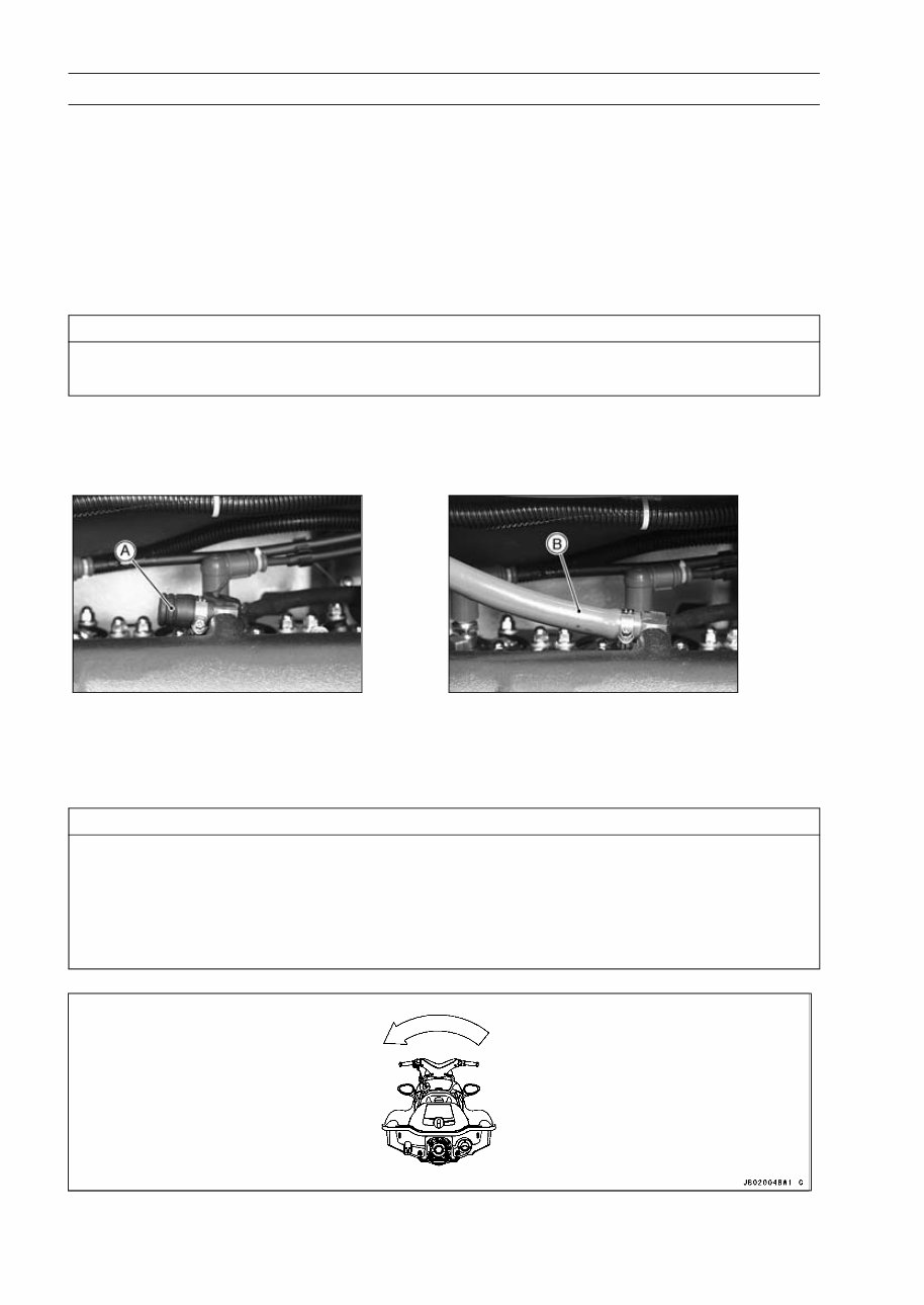
(2) Auxiliary Cooling
An auxiliary cooling supply may be used if the watercraft cannot be operated in water during ad-
justments. If possible, always operate the watercraft in water rather than use an auxiliary cooling
supply.
•
Loosen the clamp and remove the cap [A].
•
Connect the garden hose [B] to the hose fitting (see above).
•
Attach the garden hose to a faucet. Do not turn on the water until the engine is running and turn
it off immediately when the engine stops. The engine-requires 2.4 L/min (2.5 qts/min) at 1 800
r/min (rpm) and 7.0 L/min (7.4 qts/min) at 6 000 r/min (rpm).
CAUTION
Insufficient cooling supply will cause the engine and/or exhaust system to overheat and
severe damage will occur. Excessive cooling supply may kill the engine and flood the cylin-
ders, causing hydraulic lock. Hydraulic lock will cause severe damage to the engine. If the
engine dies while using an auxiliary cooling supply, the water must be shut off immediately.
Always turn the boat on its left side. Rolling to the right side can cause water in the exhaust
system to run into the engine, with possible engine damage.

GENERAL INFORMATION 1-3
Before Servicing
(3) Dirt
Before removal and disassembly, clean the “Jet Ski” watercraft. Any sand entering the engine
will shorten the life of the watercraft. For the same reason, before installing a new part, clean off
any dust or metal filings.
(4) Battery Ground
Disconnect the ground (–) wire from the battery before performing any disassembly operations
on the “Jet Ski” watercraft. This prevents the engine from accidentally turning over while work
is being carried out, sparks from being generated while disconnecting the wires from electrical
parts, as well as damage to the electrical parts themselves. For reinstallation, first connect the
positive wire to the positive (+) terminal of the battery
(5) Installation, Assembly
Generally, installation or assembly is the reverse of removal or disassembly. However, if instal-
lation or assembly sequence is given in this Service Manual, follow it. Note parts locations and
cable, wire, and hose routing during removal or disassembly so they can be installed or assem-
bled in the same way. It is preferable to mark and record the locations and routing whenever
possible.
(6) Tightening Sequence
When installing bolts, nuts, or screws for which a tightening sequence is given in this Service
Manual, make sure to follow the sequence. When installing a part with several bolts, nuts, or
screws, start them all in their holes and tighten them to a snug fit, thus ensuring that the part has
been installed in its proper location. Then, tighten them to the specified torque in the tightening
sequence and method indicated. If tightening sequence instructions are not given, tighten them
evenly in a cross pattern. Conversely, to remove a part, first loosen all the bolts, nuts, or screws
that are retaining the part a 1/4-turn before removing them.
(7) Torque
When torque values are given in this Service Manual, use them. Either too little or too much
torque may lead to serious damage. Use a good quality, reliable torque wrench.
(8) Force
Common sense should dictate how much force is necessary in assembly and disassembly. If
a part seems especially difficult to remove or install, stop and examine what may be causing the
problem. Whenever tapping is necessary, tap lightly using a wooden or plastic-faced mallet. Use
an impact driver for screws (particularly for the removing screws held by non-permanent locking
agent) in order to avoid damaging the screw heads.
(9) Edges
Watch for sharp edges, as they could cause injury through careless handling, especially during
major engine disassembly and assembly. Use a clean piece of thick cloth when lifting the engine
or turning it over.
(10)High-Flash Point Solvent
A high-flash point solvent is recommended to reduce fire danger. A commercial solvent com-
monly available in North America is standard solvent (generic name). Always follow manufacturer
and container directions regarding the use of any solvent.
(11)Gasket, O-ring
Replace a gasket or an O-ring with a new part when disassembling. Remove any foreign matter
from the mating surface of the gasket or O-ring to ensure a perfectly smooth surface to prevent
oil or compression leaks.
(12)Liquid Gasket, Locking Agent
Clean and prepare surfaces where liquid gasket or non-permanent locking agent will be used.
Apply them sparingly. Excessive amount may block engine oil passages and cause serious dam-
age.
(13)Press
When using a press or driver to install a part such as a drive shaft holder bearing, apply a small
amount of oil to the area where the two parts come in contact to ensure a smooth fit.
(14)Ball Bearing and Needle Bearing
Do not remove a ball bearing or a needle bearing unless it is absolutely necessary. Replace any
ball or needle bearings that were removed with new ones. Install bearings with the manufacturer
and size marks facing out, applying pressure evenly with a suitable driver. Apply force only to the
end of the race that contacts the press fit portion, and press it evenly over the base component.
1-4 GENERAL INFORMATION
Before Servicing
(15)Oil Seal and Grease Seal
Replace any oil or grease seals that were removed with new ones, as removal generally dam-
ages seals. Oil or grease seals should be pressed into place using a suitable driver, applying a
force uniformly to the end of seal until the face of the seal is even with the end of the hole, unless
instructed otherwise. When pressing in an oil or grease seal which has manufacturer’s marks,
press it in with the marks facing out.
(16)Circlip, Retaining Ring, and Cotter Pin
When installing circlips and retaining rings, take care to compress or expand them only enough
to install them and no more. Install the circlip with its chamfered side facing load side as well.
Replace any circlips, retaining rings, and cotter pins that were removed with new ones, as re-
moval weakens and deforms them. If old ones are reused, they could become detached while
the “Jet Ski” watercraft is driven, leading to a major problem.
(17)Lubrication
Engine wear is generally at its maximum while the engine is warming up and before all the sliding
surfaces have an adequate lubricative film. During assembly, make sure to apply oil to any sliding
surface or bearing that has been cleaned. Old grease or dirty oil could have lost its lubricative
quality and may contain foreign particles that act as abrasives; therefore, make sure to wipe it off
and apply fresh grease or oil. Some oils and greases in particular should be used only in certain
applications and may be harmful if used in an application for which they are not intended.
(18)Replacement Parts
When there is a replacement instruction, replace these parts with new ones every time they are
removed.
Replacement parts will be damaged or lose their original function once they are removed. There-
fore, always replace these parts with new ones every time they are removed. Although the pre-
viously mentioned gasket, O-ring, ball bearing, needle bearing, grease seal, oil seal, circlip, and
cotter pin have not been so designated in their respective text, they are replacement parts.
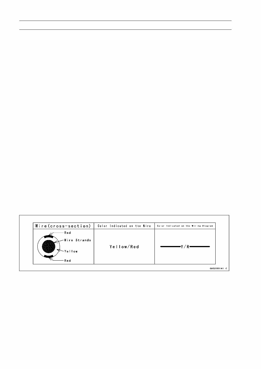
(19)Electrical Wires
All the electrical wires are either one-color or two-color. A two-color wire is identified first by the
primary color and then the stripe color. For example, a yellow wire with thin red stripes is referred
to as a “yellow/red” wire; it would be a “red/yellow” wire if the colors were reversed. Unless in-
structed otherwise, electrical wires must be connected to wires of the same color.
Two-Color Electrical
(20)Inspection
When parts have been disassembled, visually inspect these parts for the following conditions
or other damage. If there is any doubt as to the condition of them, replace them with new ones.
Abrasion Crack Hardening Warp
Bent Dent Scratch Wear
Color change Deterioration Seizure
(21)Specifications
Specification terms are defined as follows:
"Standards" show dimensions or performances which brand-new parts or systems have.
"Service Limits" indicate the usable limits. If the measurement shows excessive wear or dete-
riorated performance, replace the damaged parts.
GENERAL INFORMATION 1-5
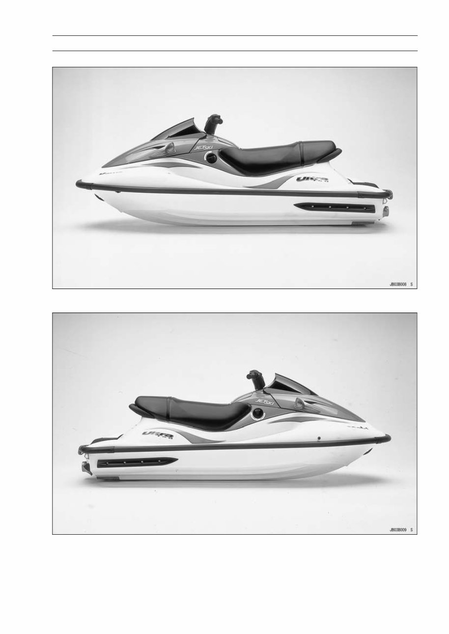
Model Identification
JH1200-B1 Left Side View
JH1200-B1 Right Side View
You're Reading a Preview
What's Included?
Fast Download Speeds
Online & Offline Access
Access PDF Contents & Bookmarks
Full Search Facility
Print one or all pages of your manual
$31.99
Viewed 53 Times Today


Secure transaction
What's Included?
Fast Download Speeds
Online & Offline Access
Access PDF Contents & Bookmarks
Full Search Facility
Print one or all pages of your manual
$31.99
- This complete factory service repair workshop manual is available for instant access on your computer, tablet, or smartphone.
- It covers all repairs, servicing, and troubleshooting procedures with detailed photos and diagrams.
- Professional mechanics and technicians use this manual, which contains step-by-step instructions and highly detailed exploded diagrams and pictures.
- You have the option to print out a single page or the entire manual.
- This manual can be used on multiple computers without any limitations or trial periods.
- There is no expiry date or renewal fee; you can use this manual for life.
- It is fully compatible with Windows and MAC computers.
For more information, please click the button below.


