

TABLE OF CONTENTS
1· DESCRIPTION & OPERATION Shallow Water Operation 2-6
Flame Arrestors 2-7
BRIEF HISTORY 1-1 Fuel System 2-7
PRINCIPLES OF OPERATION 1-2 Excessive Noise 2-8
ENGINE & JET DRIVE 1-3
Automotive Replacements 2-8
Cooling System 1-4
BOATING ACCIDENT REPORTS 2-8
Bilge Breather 1-5
SECURITY 2-8
IMPELLERS 1-6
REPLACEMENT PARTS 1-6 3. TUNING
DEBRIS REMOVAL 1-6
REVERSE CAPABILITY 1-7 INTRODUCTION 3-1
SPECIAL FEATURES 1-8 TUNE- UP SEQUENCE 3-1
RPM Limiter 1-8 COMPRESSION CHECK 3-2
Throtde Opening Limiter 1-8 SPARK PLUG INSPECTION 3-3
Self-Circling Mode 1-8 ELECTRICAL POWER SUPPLY 3-3
"Maintenance Free" Batteries 3-4
2- SAFETY Standard Batteries 3-4
INTRODUCTION 2-1 Jumper Cables 3-4
Craft Classification 2-1 CARB URETOR ADJUSTMENT 3-5
Information 2-1 Fuel & Fuel Tanks 3-5
Regulation Enforcement 2-2 Draining Fuel Tank 3-5
MINIMUM LEGAL REQUIRE-- Low Speed & Idle Adjustments 3-6
MENTS 2-2 SPECIAL TACHOMETER WORDS 3-6
Personal Flotation Devices 2-2 FUEL PUMPS 3-7
Fire Extinguisher 2-4 Remote Fuel Pump 3-7
MINIMUM LEGAL REGISTRA- Integral Fuel Pump 3-7
TION REQUIREMENTS 2-5 CRANKING MTR. & SOLENOID 3-8
SAFETY PRACTICES 2-5 Cranking Motor Test 3-8
Solenoid test 3-8
MOST IMPORTANT WORDS JET PUMP 3-8
IN THIS MANUAL 2-5 Gate Position 3-8
Impeller 3-8
Full Throttle Operation 2-5
Jumping Waves 2-6 4- MAINTENANCE
Alcohol & Substance Use 2-6
Age Restrictions 2-6 INTRODUCTION 4-1
Speed Restrictions 2-6 After Use Tasks 4-2
4- MAINTENANCE (CONTINUED) Spark Plug Evaluation 5-8
CRANKING SYSTEM FAILURES 5-9
Cooling 4-2
Faulty Symptoms 5-10
Flushing Cooling System 4-3
Cranking Circuit Tests 5-10
Controlling Corrosion 4-3
Cranking Motor Relay 5-12
Pump Impeller 4-3
Relay Removal 5-13
SERIAL NUMBERS 4-4
Relay Testing 5-13
LUBRICATION 4-4
Relay Installation 5-14
Throttle Cable 4-5
CHARGING SYSTEM
Steering Cable 4-5
MALFUNCTIONS 5-15
Fuel/Oil Mixture 4-7
TROUBLESHOOTING CHARTS 5-16
"Break-in" 4-7
Jet Pump 4-7
INSPECTION & SERVICE 4-7
6- FUEL AND OIL
Fuel Tank, Check Valve & Filter4-7
Sediment Bowl 4-8
INTRODUCTION 6-1
Fuel Tank Filters 4-8
GENERAL CARB URETION
In-Line Filter 4-8
INFORMATION 6-1
Oil Filter 4-8
FUEL COMPONENTS & AV AIL-
Drain Plug 4-8
ABLE GAS 6-3
FLUSHING
Leaded Gasoline 6-3
Cooling System 4-9
Fuel Filter & Sediment Bowl 6-4
Bilge System 4-9
In-Line Fuel Filter 6-4
IMPELLER CLEARANCE 4-9
Fuel Tank Screen Filters 6-4
PRE-SEASON PREPARATION 4-10
Air/Fuel Mixture 6-5
SEALANTS, LUBRICANTS, ETC. 4-13
Throttle & Choke Valves 6-5
FIBERGLASS HULLS 4-14
FUEL PUMP 6-5
SUBMERGED ENGINE SERVICE4-14
Remote Pump 6-5
Salt Water Submersion 4-14
Integral Fuel Pump 6-5
Submerged While Operating 4-15
OIL INJECTION 6-5
Fresh Water Submersiop- 4-15
Fuel/Oil Mixture 6-6
WINTER STORAGE 4-16
"Break-in" Lubrication 6-6
PRE-SEASON CHECK 4-17
Removing Fuel from System 6-7
ENGINE REVOLUTION
5- TROUBLESHOOTING LIMITER 6-7
TROUBLESHOOTING 6-7
INTRODUCTION 5-1
Fuel Problems 5-7
Lower than Normal RPM 5-1
Fuel Filter & Sediment Bowl 6-8
Higher than Normal RPM 5-1
"Sour" Fuel
6-,8
Engine Troubleshooting 5-2
Choke Problems 6-8
Cranking System Test 5-2
Rough Engine Idle 6-8
Ignition System Test 5-2
Excessive Fuel 6-9
Compression Test 5-3 Engine Surge 6-9
LEAK DOWN PROCEDURE 5-5 CARBURETOR MODELS 6-9
FUEL SYSTEM PROBLEMS 5-5 SERVICE KEIHIN CDK-34 6-9
Engine Surge
•
5-6 Removal & Disassembling 6-10
Rough Engine Idle 5-7 Cleaning & Inspecting 6-14
IGNITION SYSTEM FAULTS 5-7 Exploded Drawing 6-15
Interm.ittent Problems 5-8 Assembling 6-16
Installation 6-19
Priming 6-21
Mixtur~ Screws wILimiter Cap~6-22
Idle Adjustment Screw 6-22
Low & High Speed Adjustment6.:.22
High Altitude Operation 6-22
Choke Cable Adjustment 6-23
Throttle Cable Adjustment 6-23
SERVICE KEIHIN CDK-38 & 40
CARB URETOR w/INTEGRAL
FUEL PUMP
Disassembling
"Front" Side
"Back" Side
Cleaning & Inspecting
Exploded Drawing
Assembling
Installation
Priming
Choke Cable Adjustment
Throttle Cable Adjustment
REMOTE FUEL PUMP
Theory of Operation
Pump Pressure Check
Pump Volume Check
Servicing Fuel Pump
Remo:al & Disassembling
Cleamng & Inspecting
Assembling
OIL INJECTION
Oil Mixture
"Break-in" Period
System Components
Oil Tank
Oil Injection Pump
System Inspection
Oil Pump Output Test
Troubleshooting
First Checks -- Delivery
Purging Air from System
Purging Air from Pump
7- IGNITION
INTRODUCTION & CHAPTER
6-25
6-25
6-25
6-27
6-28
6-29
6-30
6-32
6-32
6-32
6-33
6-33
6-33
6-34
6-35
6-36
6-37
6-37
6-37
6-38
6-38
6-38
6-39
6-39
6-39
6-39
6-40
6-41
6-41
6-41
6-42
COVERAGE 7-1 ~
SPARK PLUG EVALUATION 7-1
Correct Color 7-2
Rich Mixture
Too Cool
Fouled
Carbon Deposits
Overheating
Electrode Wear
7-2
7-3
7-3
7-3
7-3
7-3
CDI (CAPACITOR DISCHARGE
IGNITION) & CHARGING SYS. 7-4
Description & Operation --
Ignition Circuit 7-4
Operation 7-5
Special Timing Words 7-5
Troubleshooting CDI 7-5
Spark Plugs 7-5
Compression 7-6
Testing Ignition Components 7-7
Elec. Box Removal -- 550 & 6507-8
Elec. Box Removal -- All Others 7-8
Exciter Coil Test -- 550 7-9
Pulser Coil Test -- 550 7-9
Exciter Coil Test -- 650 7-9
Igniter Test -- 550 & 650 7-10
Igniter Removal -- 550 & 650 7-10
Ign.Coil Winding Test -- 550 &
650 -- Secondary Winding 7-10
Ign. Coil Winding Test -- 750,
900 & 1100 -- Primary 7-11
Secondary Winding 7-12
CDI Igniters -- Removal,
Installation 7-12
Pickup Coil -- 750, 900 & 11007-12
IGNITION TIMING ADJUST-
MENTS 7-14
Timing -- 550 & 650 7-14
Dynamic Check 7-15
Magneto Assembly 7-15
Adjusting Timing 7-16
CHARGING CIRCUIT 7-17
Description & Operation 7-17
Troubleshooting 7-19
Testing Coil Output 7-19
Coil Resistance Test 7-21
Exciter Coil Test -- 750 7-21
Exciter Coil Test -- 900 7-21
Charging Coil Output -- 1100 7-21
Charg. Coil Resistance -- 1100 7-21
8- ENGINE EXPLODED DRAWINGS 8-55
Assembling Continues 8-57
INTRODUCTION & CHAPTER Piston Installation 8-58
ORGANIZATION 8-1 Reed Block/Intake Manifold 8-61
TWO-CYCLE ENGINE Exhaust Manifold Installation 8-61
DESCRIPTION & OPERATION 8-2 Cylinder Head Installation 8-61
Intake/Exhaust 8-2 Flywheel Installation 8-63
Lubrication 8-2 Coupler Installation 8-63
Physical Laws 8-2 Flywheel Cover Installation 8-64
Actual Operation 8-3 Oil Pump Installation 8-64
Timing 8-3 Cranking Motor Installation 8-65
SERVICE TWO-CYLINDER
ENGINE INSTALLATION
ENGINES 8-3
THREE-CYLINDER SERIES 8-65
Preliminary Task -- Engine
Engine Support Equipment 8-66
Overhaul 8-4
CLEANING & INSPECTING
Removal 8-4
ALL ENGINES 8-67
Disassembling 8-9
Reed Block Service 8-68
Cranking Mtr. Removal 8-10
Crankshaft Service 8-68
"Pulling" Flywheel 8-11
Connecting Rod Service 8-70
Magneto Assembly 8-13
Piston Service 8-70
Block· Disassembling 8-14
Cylinder Block Service 8-74
Assembling & Installation 8-20
Piston Clearance 8-75
Exploded Drawings 8-21
Honing Cylinder Walls 8-75
Lower Half 8-26
Block & Cyl. Head Warpage 8-77
Piston Installation 8-28
SEALANTS, LUBRICANTS, ETC. 8-78
Block Installation' 8-30
Cylinder Head 8-31
9- ELECTRICAL
Flywheel Installation 8-34
Cranking Motor Installation 8-37
INTRODUCTION 9-1
Engine Installation 8-39
BATTERIES 9-1
Engine Alignment 8-39
PWC Batteries 9-1
Fuel Tank Installation 8-41
Construction
9-1 '
Oil Tank Installation 8-42
Battery Ratings 9-2
SERVICE THREE-CYLINDER
Ampere-Hour 9-2
ENGINE 8-45
Cold Cranking Performance 9-2
Engine Removal 8-45
Reserve Capacity 9-2
Exhaust Manifold Removal 8-46
Watt-Hour 9-2
Engine Disassembling 8-47
Installation 9-2
Servic.e 9-2
Cranking Motor Removal 8-48
Testing 9-4
Pulling the Flywheel 8-48
Cylinder Head Removal 8-50
Hydrometers 9-5
Exhaust Manifold Removal 8-51
Charging 9-6
Intake Manifold Removal 8-51
Installing 9-6
Block Disassembling 8-52
Jumper Cables
Crankcase Separation 8-54
Storage 9-7
Crankshaft Disassembling 8-54
TACHOMETER 9-7
,ELECTRICAL SYSTEM -- GEN-
ASSEMBLING & INSTALLATION ERAL INFORMATION 9-8
THREE-CYLINDER ENGINE 8-54 Cranking Motor Circuit 9-8
Ignition
CRANKING MOTOR CIRCUIT
Theory of Operation
Cranking Motor Noises
Faulty Symptoms
CRANKING MOTOR TROUBLE-
SHOOTING
Circuit Tests
Motor Relay Removal
for Testing
Relay Testing
Relay Installation
CRANKING MOTOR SERVICE
Description
Diagrams Inside Elec. Box
Motor Removal
Disassembling
Cleaning & Inspecting
Testing Motor Parts
Assembling
Installation
TESTING OTHER ELECTRICAL
COMPONENTS
Start Button Test
Safety Switch
Stop Switch
Stop Switch Relay
Electric Bilge Pump
Electric Fan
Temperature Warning Sys.
Overheat Buzzer
ELECTRIC TRIM SYSTEM
10 JET PUMP
INTRODUCTION
Model Identification and
9-9
9-9
9-9
9-10
9-11
9-11
9-11
9-12
9-14
9-14
9-15
9-15
9-16
9-18
9-18
9-21
9-24
9-26
9-27
9-30
9-31
9-31
9-31
9-31
9-32
9-32
9-32
9-33
9-33
10-1
Chapter Coverage 10-1
Jet Pump Description 10-2
Axial Flow 10-2
Mixed Flow 10-2
IMPELLERS 10-3
Cavitation Burns 10-3
Cooling Water and Bilge Hoses1O-4
I
IMPELLER-TO-PUMP CASE
CLEARANCE 10-5
Axial Flow Pump 10-5
Mixed Flow Pump 10-6
JET PUMP SERVICE 10-6
Removal 10-7
Impeller Alignment 10-9
Disassembling 10-10
Impeller Removal 10-12
Impeller Shaft Removal 10-13
Cleaning & Inspecting 10-15
Exploded Drawings 10-16
Assembling 10-20
Shimming Procedures -- 550 10-'21
Impeller Installation --550 10-23
Impeller Installation -- All
Others 10-25
Pump Installation 10-27
BEARING HOUSING SERVICE 10-30
Removal 10-30
. Disassembling 10-31
Cleaning & Inspecting 10-32
11 CONTROL ADJUSTMENTS
INTRODUCTION 11-1
STEERING CABLE 11-1
REVERSE CABLE 11-2
TRIM CABLE 11-3
APPENDIX
METRIC CONVERSION CHART A-I
RECOMMENDED TORQUE
VALUES A-2
ENGINE SPECIFICATIONS AND
TUNE- UP ADJUSTMENTS A-4
WIRING DIAGRAMS & COLOR
CODE IDENTIFICATION
Model 550 Series
Model 650 Series
Model 750 Series
Model 750 Hi-Performance
Model 900 Hi-Performance
Model 1100 Hi-Performance
A-6
A-6
A-7
A-8
A-9
A-I0
A-ll
1
DESCRIPTION & OPERATION
1·1 BRIEF HISTORY
The jet drive system for propelling a craft
through the water arrived on the scene in the
mid 1960's with the jet drive boat. In those
early days, the jet drive system was mated only
with high performance powerplants -- engines
in the 454 cu. in. class and larger. For this
reason, during the "gas crunch" in the 1970's
the jet drives were labeled as inefficient and as
"gas hogs".
In addition to these two negative terms, they
earned the reputation as "bad boy" boats due to
their noisy "straight" exhaust, high rpm opera-
tion, and their almost unbelievable maneuver-
ability. These combined factors did little to
enhance their image and certainly restricted
their popularity.
With new. and improved technology, per-
sonal watercraft arrived on the scene about the
mid 1970's. Personal watercraft, as we know
them today, were developed using the same
principles as the jet boats, and originally pow-
ered with a single cylinder two-stroke engine.
In order to meet the demand for more
speed and the ability to carry more than just
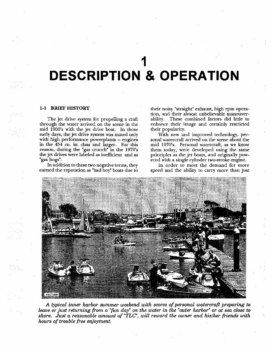
A typical inner harbor summer weekend with scores of personal watercraft preparing to
leave or just returning from a "fun day" on the water in the "outer harbor" or at sea close to
shore. Just a reasonable amount of "TLC", will reward the owner and his/her friends with
hours of trouble free enjoyment.
'-2 DESCRIPTION & OPERATION
onc person, watercraft manufacturers were
quick to respond. Today, most modem craft
are powered with a twin cylinder or three-
cylinder two-stroke powerplant, coupled to a
single stage pump.
Aftermarket shops and manufacturers have
come into existence 311 acroros the United States
and Canada. Their cmput of specialty products
and services pennit the owner [Q gain more
speed and in over the competition at racing
evcnlll wherever enough water is available.
As mentioned in the ~Forewordft. this book
has been designed and written to cover stock,
factory "out the door" engines and jet drives.
Modifications for higher than manufa curer's
rated performance are so extensive and varied,
no attempt has been made to include them in
this volume. (Actually, for such coverage, a
separate comprehensive book would be re~
quired.) In such cases the publisher's recom~
mendation is La follow the after market iustruc·
tion with the partirular product or service.
Series Covered.
The following KHwHsHki seri es produced
from 1992 thru 1998 are covered in r.his manu~
aI.
Model
J5550 Series
J F650 Series
JL650 Series
JS650 Series
JS750 Series
]H750 Series
JT7!S0 Series
JH900 Series
JT900 Series
]H 1100 Series
JTl100 $eries
ApproL Yr. of
Production
1992-1994
1992-1996
1992-1995
1992-1993
1992-1996
1992 & On
1994 & On
1995 & On
1997 & On
1996 & On
1997 & On
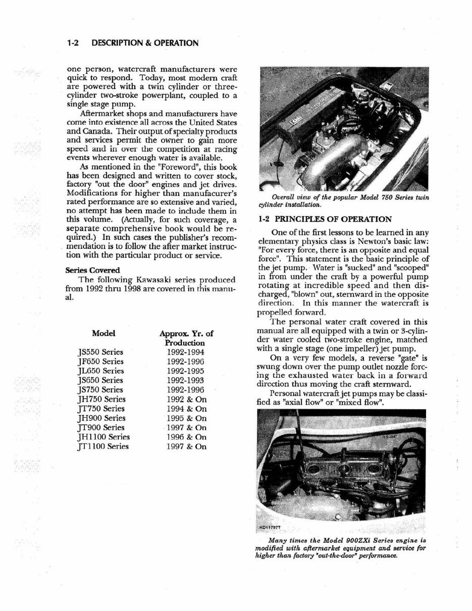
Overall view of the popular Model 750 Seiu twin
cylinder installation.
1-2 PRINCIPLES OF OPERATION
One of the first lessons to be lea rned in any
elementary physics class is Newton's basic law:
HFor every force, there is an opposite and equal
force ". This statement is the basic principle of
the jet pump. Water is "sucked" and "scooped"
in from under the craft by a powerful pump
rotating at incr e dible speed and then dis~
charged, Itblown~ out, stemward in the opposite
direction . In this manner the watercraft is
propelled fOlWard.
The personal water craft covered in this
manual are all equipped with a twin or 3-cylin-
der water cooled £wo-stroke engine, matched
with a single uage (one impeUer)je[ pump.
On a very few models. a reverse "gate is
swung down over the pump oullet nozzle forc-
ing the e xhaust ed wa ter back in a forward
direction thus moving the craft ste mward.
Personal watercraft jet pumps may be classi-
fi ed as "axial flow" or "mixed flow".
Many time. the Model 900ZXi Serie. engine i.
modified with a{rermarket equipment and service for
higher than factory 'out-the-door" performance.
IMP
SHAFT
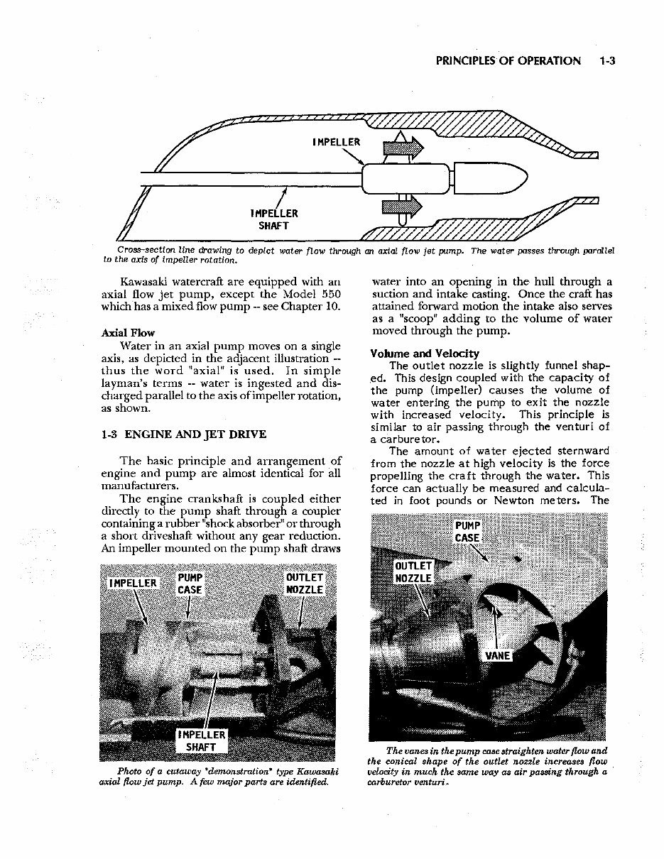
PRINCIPLES OF OPERATION 1-3
Cross-section line drawing to depict water flow through an axial flow jet pump. The water passes through parallel
to the axis of impeller rotation.
Kawasaki watercraft are equipped with an
axial flow jet pump, except the Model 550
which has a mixed flow pump -- see Chapter 10.
Axial Flow
Water in an axial pump moves on a single
axis, as depicted in the adjacent illustration --
thus the word "axial" is used. In simple
layman's terms -- water is ingested and dis-
charged parallel to the axis ofimpeller rotation,
as shown.
1-3 ENGINE AND JET DRIVE
The basic principle and arrangement of
engine and pump are almost identical for all
manufacturers.
The engine crankshaft is coupled either
directly to the pump shaft through a coupler
containing a rubber "shock absorber" or through
a short driveshaft without any gear reduction.
An impeller mounted on the pump shaft draws
Photo of a cutaway "demonstration" type Kawasaki
axial flow jet pump. A few major parls are identified.
water into an opening in the hull through a
suction and intake casting. Once the craft has
attained forward motion the intake also serves
as a "scoop" adding to the volume of water
moved through the pump.
Volume and Velocity
The outlet nozzle is slightly funnel shap-
ed. This design coupled with the capacity of
the pump (impeller) causes the volume of
water entering the pump to exit the nozzle
with increased velocity. This principle is
similar to air passing through the venturi of
a carburetor.
The amount of water ejected sternward
from the nozzle at high velocity is the force
propelling the craft through the water. This
force can actually be measured and calcula-
ted in foot pounds or Newton meters. The
The vanes in the pump case straighten water flow and
the conical shape of the outlet nozzle increases flow
velocity in much the same way as air paBBing through a '
carburetor venturi.
1-4 DESCRIPTION & OPERATION
greater the velocity of water mass moving
through the nozzle, the greater the thrust to
move the craft.
Cooling System
A fitting on the jet. pump, aft of the
impeller, syphens off cooling water. This
water is delivered first to the exhaust mani-
fold -- the hottest part of the engine. The
water is then channeled around the cylinder
walls, cylinder head and exhaust pipe.
After the exhaust pipe, some water is chan-
neled overboard through a bypass hose.
The remaining water is mixed with exhaust
gases in an expansion chamber and finally
discharged from the exhaust outlet. This mix-
ture of water and exhaust gases has the affect of
cooling and somewhat quieting the exhaust
emission.
On all models, a bypass hose connects the
exhaust pipe water jacket to an outlet on the
starboard side of the hull. When water is dis-
charged as a "tattle-tale" stream, the operator is
assured cooling water is circulating through the
engine properly.
Cooling Water and Bilge Hoses
On most pumps two hoses are attached
to the pump case and outlet nozzle. One
hose channels some of the water flowing
through the pump to the exhaust manifold --
the hottest part of the engine -- to cool the
block during operation. The other hose
siphons water out of the bottom of the hull,
A feeler gauge may be used to measure the clearance
between the impeller blades and the pump case.
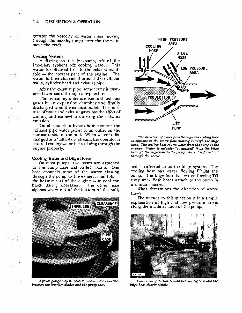
HIGH PRESSURE
COOLING AREA
JET
PUMP
The direction of water flow through the cooling hose
is opposite to the water flow moving through the bilge
hose. The cooling hose routes water from the pump to the
engine. Water is actually ·vacuumed" from the bilge
through the bilge hose to the pump where it is forced out
through the nozzle.
and is referred to as the bilge system. The
cooling hose has water flowing FROM the
pump. The bilge hose has water flowing TO
the pump. Both hoses attach to the pump in
a similar manner.
What determines the direction of water
flow?
The answer to this question is in a simple
explanation of high and low pressure areas
along the inside surface of the pump.
Close view of the nozzle with the cooling hose and the
bilge hose clearly visible.
The bilge fitting protrusion extends into the water
flow area. Water passing through causes a low pressure
area a ·vacuuming· - siphoning -- effect - sucking water
out of the bilge.
<::lose inspection of the area inside the
pump at the cooling water hose fitting re-
veals a smooth rounded shoulder with no
obstruc tion or obstacle to impede the flow
of water. A high pressure area develops
here and draws the water down the hose
attached to the fitting.
Further inspection of the area inside the
hosing at the bilge hose fitting reveals a
small protrusion around the opening. This
protrusion causes disturbance to the water
flow and creates an area of low pressure.
This low pressure area will have the effect
of emptying air and water from the hose aft
with the impeller water flow -- similar to
the action of a vacuum cleaner, as depicted
in the accompanying illustration. If the
Location of the bilge pickup in the lowest part of the
engine compartment. (Photograph taken with the engine
removed for clarity.
ENGINE & JET DRIVE 1-5
other end of the hose is sUbmerged in water
inside the hull, the water will be "vacuum-
ed
ll
out. In this manner the bilge system
drains the bilge.
Many an owner -- with good intentions --
thinking his action would smooth water flow
and increase pump performance -- has filed
the protrusion described in the previous par-
agraph smooth with the surrounding area of
the pump. 'During operation of the water
craft, the bilge system worked in REVERSE.
Water was pumped from the impeller hous-
ing into the bilge area, quickly filling the
bilge and possibly sinking the craft before
the rider had time to realize what was
happening.
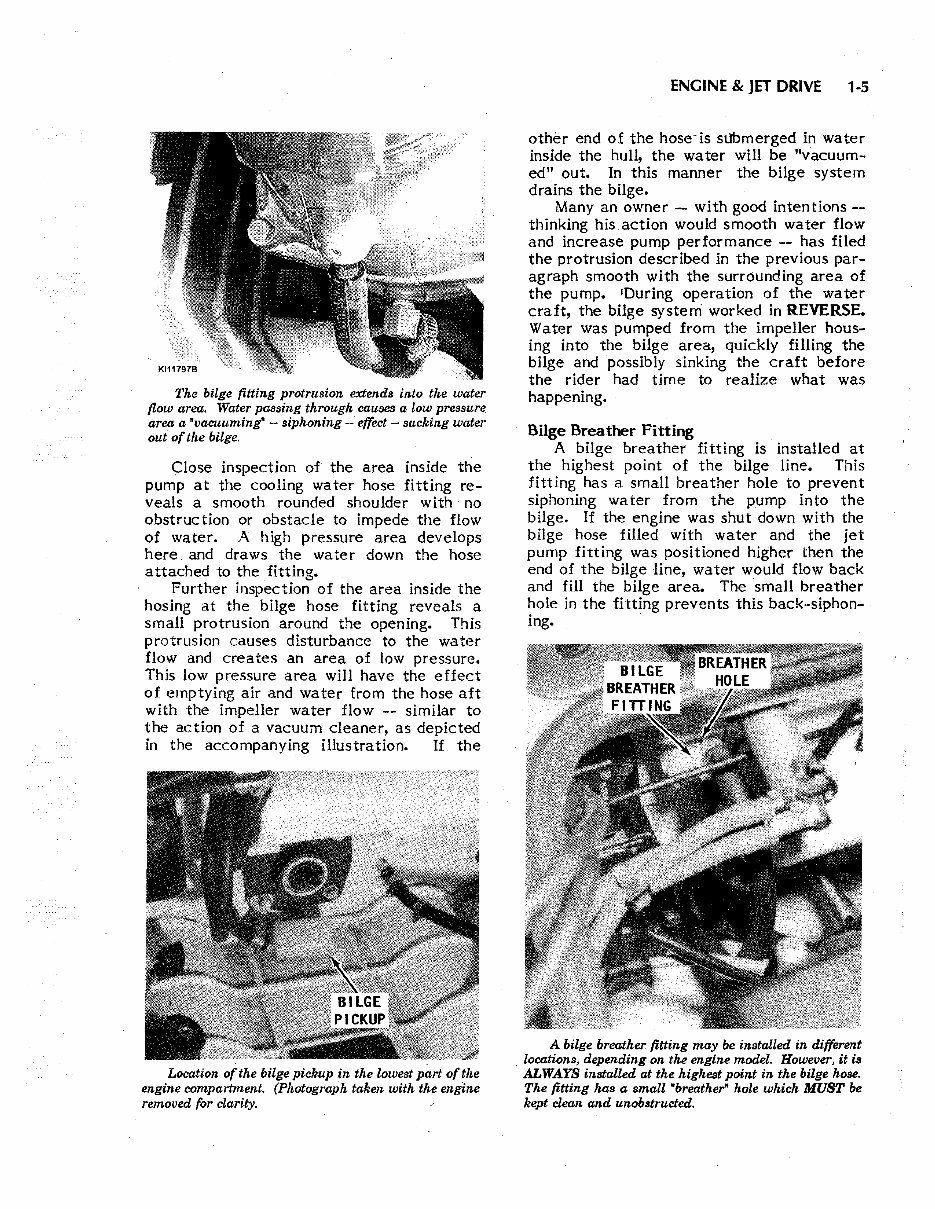
Bilge Breather Fitting
A bilge breather fitting is installed at
the highest point of the bilge line. This
fitting has a small breather hole to prevent
siphoning water from the pump into the
bilge. If the engine was shut down with the
bilge hose filled with water and the jet
pump fitting was positioned higher then the
end of the bilge line, water would flow back
and fill the bilge area. The small breather
hole in the fitting prevents this back-siphon-
ing. .
A bilge breather fitting may be installed in different
. locations, depending on the engine model. However, it is
ALWAYS installed at the highest point in the bilge hose.
The fitting has a small "breather" hole which MUST be
kept clean and unobstructed.
You're Reading a Preview
What's Included?
Fast Download Speeds
Online & Offline Access
Access PDF Contents & Bookmarks
Full Search Facility
Print one or all pages of your manual
$31.99
1992-1997 Kawasaki JS550 JF650 JL650 JS650 JS750 JH750 JT750 JH900 JT900 JH1100 JT1100 Jet Ski Watercraft Repair Manual
Viewed 16 Times Today

What's Included?
Fast Download Speeds
Online & Offline Access
Access PDF Contents & Bookmarks
Full Search Facility
Print one or all pages of your manual
$31.99

Secure transaction
What's Included?
Fast Download Speeds
Online & Offline Access
Access PDF Contents & Bookmarks
Full Search Facility
Print one or all pages of your manual
- The manual covers the following machines: 1992-1997 KAWASAKI JS550 JF650 JL650 JS650 JS750 JH750 JT750 JH900 JT900 JH1100 JT1100 JETSKI PERSONAL WATERCRAFT.
- Instant access after payment.
- No software or complicated loading process, just plain, simple, and easy-to-use PDF files.
- GearHead Manuals is your only source for repair, service, and shop manuals.
- Our repair manual, owner's manuals, and parts catalogs contain all the information you'll need for repairs, parts lookup, or routine maintenance on your machine.
- You will have access to information regarding the following topics:
- General Information
- Routine Maintenance
- Engine Removal and Installation
- Fuel System
- Lubrication and Cooling System
- Engine Specifications
- Transmission, Drive Chain & Sprockets
- Steering System
- Shocks
- Body Work
- Intake & Exhaust
- Electrical System
- Advanced Troubleshooting
- And more!
- With our downloadable repair manual PDFs, find the page pertaining to your job, print it off, and start working on your machine without ruining your expensive paper shop manual with grease and dirt.
- If you're broken down on the trail or site and have a smartphone, our downloadable repair manuals provide an easy way to find your problem and repair it on the spot, minimizing downtime on the job site.
- All our repair manuals come with a Lifetime Protection Policy. If lost or damaged, simply contact us, and we'll replace it free of charge for life.
- We provide various repair service manuals, workshop manuals, repair manuals, owner's manuals, parts catalogs, and other various PDFs.
- All in an electronic PDF format.
- Manuals cover UTVs, motorcycles, ATVs, quads, snowmobiles, Seadoos, equipment, small engines, inboards, outboards, and more.
- Instant download with no shipping cost.
- Get a PDF so no waiting, repair it now.
- If you are looking for a specific manual and cannot find it, contact our customer support team via the CONTACT US LINK ABOVE with details of the required manual, and we will do our absolute best to find and list it for you.
- Instant download after payment. Thank you.


