I SECTION SUB-SECTION PAGE SAFETY NOTICE ............................................................................................................. II INTRODUCTION .............................................................................................................. III 01 MAINTENANCE 01 - Table of Contents ........................................................................................... 01-01-1 02 - Periodic Inspection Chart ............................................................................... 01-02-1 03 - Flushing and Lubrication ................................................................................ 01-03-1 04 - Water-Flooded Engine ................................................................................... 01-04-1 05 - Storage .......................................................................................................... 01-05-1 02 TROUBLESHOOTING ........................................................................................................................................ 02-01-1 03 ENGINE 01 - Table of Contents ........................................................................................... 03-01-1 02 - Engine Leak Test............................................................................................ 03-02-1 03 - Removal and Installation ................................................................................ 03-03-1 04 - Magneto System ........................................................................................... 03-04-1 05 - Top End .......................................................................................................... 03-05-1 06 - Bottom End.................................................................................................... 03-06-1 07 - Rotary Valve ................................................................................................... 03-07-1 08 - Exhaust System............................................................................................. 03-08-1 04 COOLING SYSTEM 01 - Table of Contents ........................................................................................... 04-01-1 02 - Components .................................................................................................. 04-02-1 03 - Circuit............................................................................................................. 04-03-1 05 FUEL SYSTEM 01 - Table of Contents ........................................................................................... 05-01-1 02 - Fuel Circuit ..................................................................................................... 05-02-1 03 - Air Intake........................................................................................................ 05-03-1 04 - Carburetors .................................................................................................... 05-04-1 06 LUBRICATION SYSTEM 01 - Table of Contents ........................................................................................... 06-01-1 02 - Oil Injection System....................................................................................... 06-02-1 03 - Oil Injection Pump ......................................................................................... 06-03-1 07 ELECTRICAL SYSTEM 01 - Table of Contents ........................................................................................... 07-01-1 02 - Ignition System.............................................................................................. 07-02-1 03 - Charging System ........................................................................................... 07-03-1 04 - Starting System ............................................................................................. 07-04-1 05 - Instruments and Accessories ........................................................................ 07-05-1 06 - Digitally Encoded Security System ................................................................ 07-06-1 08 PROPULSION SYSTEM 01 - Table of Contents ........................................................................................... 08-01-1 02 - Jet Pump ....................................................................................................... 08-02-1 03 - Drive System ................................................................................................. 08-03-1 04 - Reverse System ............................................................................................ 08-04-1 05 - Variable Trim System ..................................................................................... 08-05-1 09 STEERING SYSTEM 01 - Table of Contents ........................................................................................... 09-01-1 02 - SP and SPX Models ....................................................................................... 09-02-1 03 - GTS Model ..................................................................................................... 09-03-1 04 - GS, GSI, GSX, GTI and GTX Models .............................................................. 09-04-1 05 - XP and HX Models ......................................................................................... 09-05-1 06 - Alignment ...................................................................................................... 09-06-1 10 SUSPENSION 01 - Table of Contents ........................................................................................... 10-01-1 02 - Direct Action Suspension .............................................................................. 10-02-1 11 HULL/BODY 01 - Table of Contents ........................................................................................... 11-01-1 02 - Adjustment and Repair .................................................................................. 11-02-1 12 TECHNICAL DATA 01 - SP and SPX Models ....................................................................................... 12-01-1 02 - GS and GSI Models ....................................................................................... 12-02-1 03 - GSX Model ..................................................................................................... 12-03-1 04 - GTS Model ..................................................................................................... 12-04-1 05 - GTI and GTX Models...................................................................................... 12-05-1 06 - HX and XP Models ......................................................................................... 12-06-1 13 WIRING DIAGRAMS.......................................................................................................................................... 13-01-1 TABLE OF CONTENTS www.SeaDooManuals.net
II SAFETY NOTICE This manual was primarily published to be used by watercraft technicians trained by the manufacturer who are already familiar with all service and maintenance procedures relating to Bombardier made Sea- Doo watercraft. Please note that the instructions will apply only if proper hand tools and special service tools are used. It is understood that this manual may be translated into another language. In the event of any discrepan- cy, the English version shall prevail. The content depicts parts and/or procedures applicable to the particular product at its time of manufac- ture. It does not include dealer modifications, whether authorized or not by Bombardier, after manufac- turing the product. The use of Bombardier parts is most strongly recommended when considering replacement of any com- ponent. Dealer and / or distributor assistance should be sought in case of doubt. Torque wrench tightening specifications must be strictly adhered to. Locking devices (ex.: locking disk, lock nut) must be installed or replaced with new ones, where specified. If the efficiency of a locking device is impaired, it must be renewed. This manual emphasizes particular information denoted by the wording and symbols; NOTE: Indicates supplementary information needed to fully complete an instruction. Although the mere reading of such information does not eliminate the hazard, your understanding of the information will promote its correct use. Always use common shop safety practice. This information relates to the preparation and use of Bombardier watercraft and has been utilized safely and effectively by Bombardier Inc. However, Bombardier Inc. disclaims liability for all damages and/or injuries resulting from the improper use of the contents. We strongly recommend that any services be carried out and/or verified by a highly skilled professional technician. It is understood that certain modifi- cations may render use of the watercraft illegal under existing federal, provincial and state regulations. ◆ WARNING Identifies an instruction which, if not followed, could cause serious personal injury including possibility of death. - CAUTION Denotes an instruction which, if not followed, could severely damage watercraft components. SAFETY NOTICE www.SeaDooManuals.net
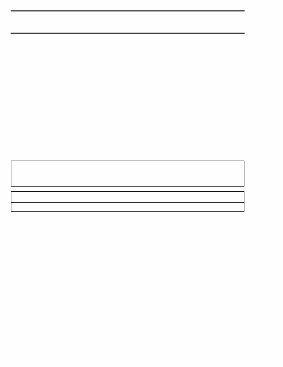
III INTRODUCTION This Shop Manual covers BOMBARDIER made SEA-DOO ® watercraft models SP 5879, SPX 5834/5661, XP 5662, GS 5621, GSI 5622, GSX 5624, GTS 5818, GTI 5641, GTX 5642 and HX 5882. HULL IDENTIFICATION NUMBER (H.I.N.) SP, SPX, GTS and HX Models It is located at right rear side of hull. 1. Hull Identification Number (H.I.N.) XP, GS, GSI, GSX, GTI and GTX Models It is located on floorboard at the rear of the water- craft. 1. Hull Identification Number (H.I.N.) All Models The Hull Identification Number is composed of 9 digits: ENGINE IDENTIFICATION NUMBER (H.I.N.) 717 Engines The Engine Identification Number is located on the upper side of the magneto housing. TYPICAL 1. Engine Identification Number (E.I.N.) F01L45A 1 F07A01A 1 Z Z N 1 2 3 4 5 L 4 9 5 Model year Serial number* *A letter may also be used as a digit. F00A0CA Month of production Year of production *A letter may also be used as a digit. 1 F01D01A 1997 BOMBARDIER WATERCRAFT SHOP MANUAL www.SeaDooManuals.net
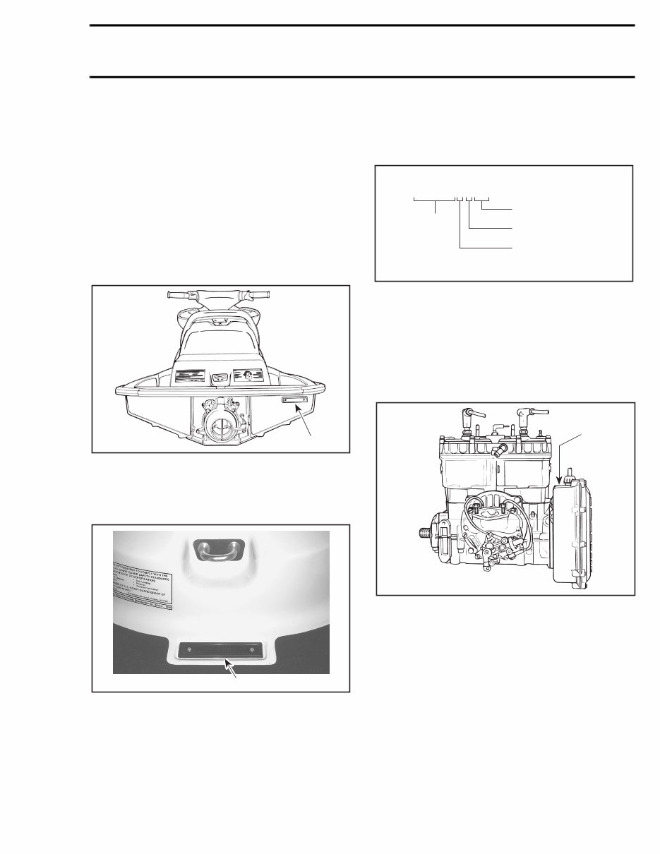
IV 787 Engine The Engine Identification Number is located on the crankcase on PTO side. 1. Engine Identification Number (E.I.N.) ARRANGEMENT OF THIS MANUAL The manual is divided into 13 major sections: 01 MAINTENANCE 02 TROUBLESHOOTING 03 ENGINE 04 COOLING SYSTEM 05 FUEL SYSTEM 06 LUBRICATION SYSTEM 07 ELECTRICAL SYSTEM 08 PROPULSION SYSTEM 09 STEERING SYSTEM 10 SUSPENSION 11 HULL/BODY 12 TECHNICAL DATA 13 WIRING DIAGRAMS Several sections are divided in various sub-sections. There is a table of contents at the beginning of many sections. F01D87A 1 1997 BOMBARDIER WATERCRAFT SHOP MANUAL www.SeaDooManuals.net
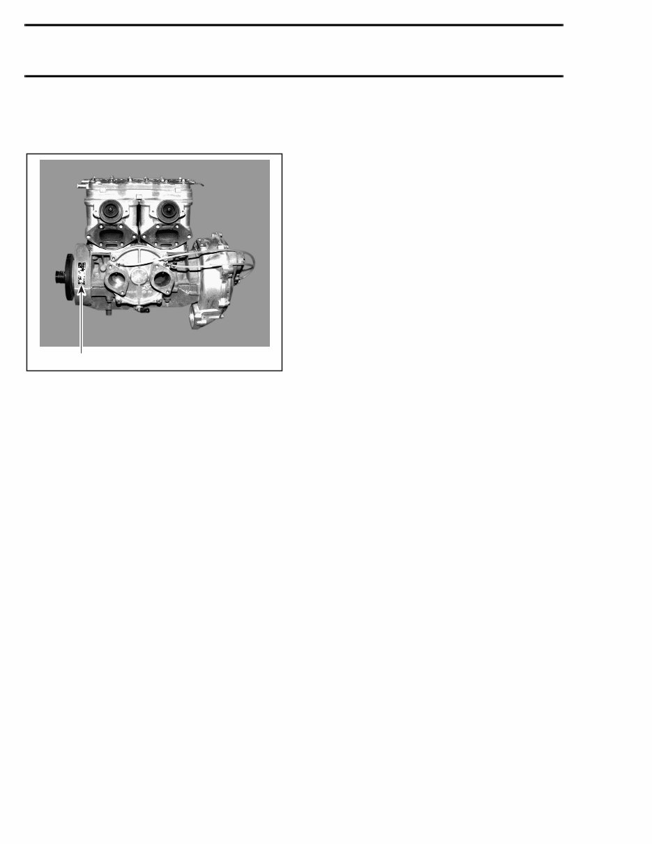
V Section 03 ENGINE Sub-Section 04 (MAGNETO SYSTEM) MAGNETO SYSTEM 717 Engine 03-04-1 F01D4WS 12 11 5 N•m (44 lbf•in) 13 9 N•m (80 lbf•in) Loctite 242 4 6 8 Loctite 242 7 6 N•m (53 lbf•in) Loctite 242 6 N•m (53 lbf•in) 9 Loctite 242 5 6 N•m (53 lbf•in) 3 14 Loctite 242 4 Loctite 648 10 15 145 N•m (107 lbf•ft) Anti-seize lubricant 2 9 N•m (80 lbf•in) 1 Page heading indicates section and sub-section detailed. Tightening torque nearby fastener. In this case, nut must be torqued to 145 N•m (107 lbf•ft). Exploded view assits you in identifying parts and related positions. TYPICAL PAGE F01A09S Illustration number for publishing process. Sub-section title indicates beginning of the sub-section. Dotted box contains parts of a particular model or an exploded view. Page numbering system: 03: ENGINE section 04: MAGNETO SYSTEM sub-section 1: First page of this sub-section Italic sub-tiltle above exploded view indicate pertaining models. Drop represents a liquid product to be applied to a surface. In this case Loctite 242 to screw threads. Bold face number indicates special procedure concerning this part. Pay attention to torque specifi- cations. Some of these are in lbf•in instead of lbf•ft. Use appro- priate torque wrench. CAUTION ▼ 1997 BOMBARDIER WATERCRAFT SHOP MANUAL www.SeaDooManuals.net
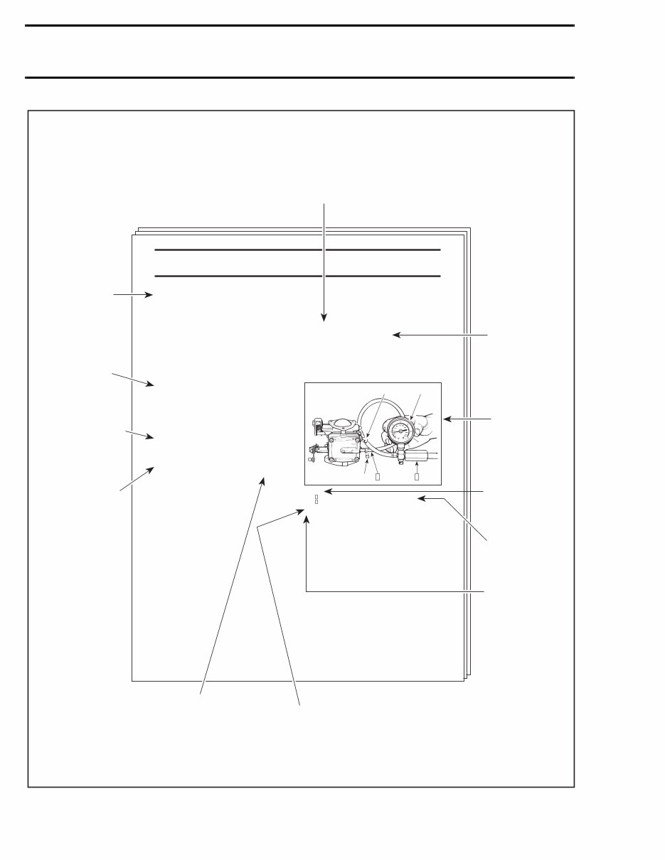
VI 1 2 Section 06 FUEL SYSTEM Sub-Section 03 (CARBURETORS) 06-03-4 Step : Install pump gauge tester to pulse nipple Step : Pump tester until it reaches the desired pressure 1. Fuel outlet nipple 2. Fuel inlet nipple A. 28 kPa (4 PSI) 3, Diaphragm XP Model Only CARBURETOR REMOVAL Inspect parts for corrosion dammage (shaft, butterfly, spring screw, check valve housing, etc.). PUMP DIAPHRAGM LEAK TEST TYPICAL To remove carburetors from engine, proceed as fol- lows: Remove air vent tube support. Unlock retaining slides holding air intake silencer base. Remove air intake silencer base from watercraft. Remove screws holding flame arrester base support to cylinder head cover. Unscrew base retaining screws then remove base from carburetors and move to front of watercraft. Turn the valve to OFF position. NOTE: For fuel line removal, use pliers (P/N 295 000 054). Disconnect pulse line from fuel pump. Disconnect fuel fuel supply line from fuel pump. Disconnect fuel return line. Disconnect oil injection pump cable, throttle cable and choke cable. Remove screws no. 6 and lock washers no. 7 retaining carburetors. All Others Models Remove 4 bolts no. 8 and lock washers no. 12 from rotary valve cover then move carburetors and rotary valve cover on top of engine. NOTE: When removing rotary valve cover , pay attention that the rotary valve stay in place, other-wise it must be timed. Remove carburetors from intake manifold. Disconnect fuel bypass line between carburetors (twin carburetors). Remove carburetor(s) from rotary valve cover. DISASSEMBLY AND INSPECTION Using a suitable pump gauge tester, perform the fol- lowing test proceeding as follows: - Install pump gauge tester (P/N 295 000 083) on pulse nipple. - Pump tester until it reaches 28 kPa (4 PSI). Diaphragm must stand pressure for 10 seconds. If pressure drops, replace diaphragm. TYPICAL PAGE Sub-title with part number(s) from exploded view followed by part name(s). ''TYPICAL'' mention indicates a general view which does not represent full detail. Sub-sub-title in this case indicates that particular procedure for XP is finished, so from this point, all others models are concerned. Title in italic indicates a particular procedure concerning a model. Service tool to be used to perform a certain procedure. Title indicates main procedure to be carried-out. F01A0AS Sub-sub-title in capital indicates a particular testing, adjustment or repair procedure. Illustration always follows text it is pertained to. Numbers in a frame are used to give a sequence to be perfomed. Numbers are used for desciption of components. Letters are used for any measures. F01F0XB A 2 1 1 2 Bold numbers in the text refer to the parts shown in the exploded view at the beginning of the sub-section. 1997 BOMBARDIER WATERCRAFT SHOP MANUAL www.SeaDooManuals.net
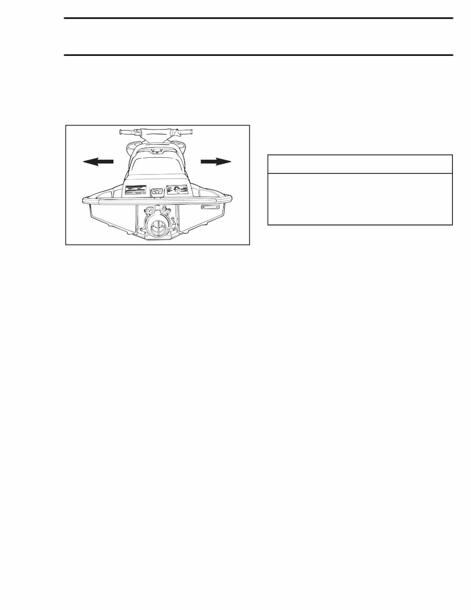
VII GENERAL INFORMATION The use of RIGHT and LEFT indications in the text, always refers to driving position (when sitting on watercraft). 1. Left (port) 2. Right (starboard) The information and component/system descrip- tions contained in this manual are correct at time of publication. Bombardier Inc. however, main- tains a policy of continuous improvement of its products without imposing upon itself any obliga- tion to install them on products previously manu- factured. Bombardier Inc. reserves the right at any time to discontinue or change specifications, designs, features, models or equipment without incurring obligation. This Shop Manual uses technical terms which may be different from the ones of the Parts Cata- logs. When ordering parts always refer to the specif- ic model Parts Catalogs. ILLUSTRATIONS AND PROCEDURES The illustrations show the typical construction of the different assemblies and, in all cases, may not reproduce the full detail or exact shape of the parts shown, however, they represent parts which have the same or a similar function. As many of the procedures in this manual are in- terrelated, we suggest, that before undertaking any task, you read and thoroughly understand the entire section or sub-section in which the proce- dure is contained. A number of procedures throughout the book re- quire the use of special tools. Before undertaking any procedure, be sure that you have on hand all the tools required, or approved equivalents. Technical Publications Bombardier Inc. Valcourt (Quebec), Canada F01L45B 1 2 - CAUTION These watercraft are designed with parts di- mensioned in both the metric and the impe- rial systems. When replacing fasteners, make sure to use only those recommended by Bombardier. 1997 BOMBARDIER WATERCRAFT SHOP MANUAL www.SeaDooManuals.net
The Seadoo GTX 5642 1997 Factory Service Repair Manual is a comprehensive resource for all your repair and adjustment needs for the Seadoo GTX 5642 1997. It serves as a valuable reference for both professional mechanics and DIY enthusiasts, offering detailed explanations for installation, removal, disassembly, assembly, repair, and check procedures in a clear and sequential manner.
This manual is known by various names, including Seadoo GTX 5642 1997 service manual, repair manual, workshop manual, and shop manual. Rest assured, all these names refer to the same manual.
Upon purchase, you can immediately access the manual, allowing you to get the job done without delay. The manual is organized into chapters, each covering essential aspects of the Seadoo GTX 5642 1997:
Maintenance
Troubleshooting
Engine
Cooling system
Fuel system
Lubrication system
Electrical system
Propulsion system
Steering system
Suspension
Hull/Body
Technical data
Wiring diagrams
Each chapter is further divided into sections, with each section containing sub-sections. The manual includes exploded diagrams at the beginning of each removal and disassembly section to aid in part identification and procedure clarification. It is available in PDF format, allowing for easy printing of specific pages or the entire manual as needed.
Recently Viewed
5,521,897Happy Clients
2,594,462eManuals
1,120,453Trusted Sellers
15Years in Business
Price:
Actual Price:
Seadoo GTX 5642 1997 Factory Service Repair Manual