I SECTION SUBSECTION PAGE SAFETY NOTICE ................................................................................................................................... III WHAT’S NEW ....................................................................................................................................... IV INTRODUCTION ................................................................................................................................... V 01 SERVICE TOOLS AND PRODUCTS 01 - Mandatory service tools ............................................................ 01-01-1 02 - Optional service tools................................................................ 01-02-1 03 - Service products ....................................................................... 01-03-1 02 MAINTENANCE 01 - Table of contents ...................................................................... 02-01-1 02 - Periodic inspection chart ........................................................... 02-02-1 03 - Flushing and lubrication............................................................. 02-03-1 04 - Water-flooded engine................................................................ 02-04-1 05 - Storage ...................................................................................... 02-05-1 03 TROUBLESHOOTING 01 - Troubleshooting ........................................................................ 03-01-1 04 ENGINE 01 - Table of contents ...................................................................... 04-01-1 02 - Leak test ................................................................................... 04-02-1 03 - Removal and installation ........................................................... 04-03-1 04 - Magneto system ....................................................................... 04-04-1 05 - Top end ..................................................................................... 04-05-1 06 - Bottom end ............................................................................... 04-06-1 07 - Rotary valve............................................................................... 04-07-1 08 - Exhaust system......................................................................... 04-08-1 05 COOLING SYSTEM 01 - Table of contents ...................................................................... 05-01-1 02 - Circuit, components and care ................................................... 05-02-1 06 FUEL SYSTEM 01 - Table of contents ...................................................................... 06-01-1 02 - Fuel circuit ................................................................................. 06-02-1 03 - Air intake ................................................................................... 06-03-1 04 - Carburetor ................................................................................. 06-04-1 07 LUBRICATION SYSTEM 01 - Table of contents ...................................................................... 07-01-1 02 - Oil injection system................................................................... 07-02-1 03 - Oil injection pump ..................................................................... 07-03-1 08 ELECTRICAL SYSTEM 01 - Table of contents ...................................................................... 08-01-1 02 - Ignition system.......................................................................... 08-02-1 03 - Charging system ....................................................................... 08-03-1 04 - Starting system ......................................................................... 08-04-1 05 - Instruments and accessories .................................................... 08-05-1 06 - Digitally encoded security system ............................................ 08-06-1 09 PROPULSION SYSTEM 01 - Table of contents ...................................................................... 09-01-1 02 - Jet pump ................................................................................... 09-02-1 03 - Drive system ............................................................................. 09-03-1 04 - Reverse system ........................................................................ 09-04-1 05 - Variable trim system ................................................................. 09-05-1 TABLE OF CONTENTS www.SeaDooManuals.net
II 10 STEERING SYSTEM 01 - Table of contents ...................................................................... 10-01-1 02 - SPX model ................................................................................ 10-02-1 03 - GTS model ................................................................................ 10-03-1 04 - GS, GSX Limited, GTI and GTX Limited .................................... 10-04-1 05 - XP Limited ................................................................................ 10-05-1 06 - Alignment ................................................................................. 10-06-1 11 SUSPENSION 01 - Table of contents ...................................................................... 11-01-1 02 - Direct action suspension .......................................................... 11-02-1 12 HULL/BODY 01 - Table of contents ...................................................................... 12-01-1 02 - Adjustment and repair .............................................................. 12-02-1 13 TECHNICAL DATA 01 - SPX model ................................................................................ 13-01-1 02 - GS and GSX Limited ................................................................. 13-02-1 03 - XP Limited ................................................................................ 13-03-1 04 - GTS model ................................................................................ 13-04-1 05 - GTI and GTX Limited................................................................. 13-05-1 14 WIRING DIAGRAMS 01 - Wiring diagrams ........................................................................ 14-01-1 TABLE OF CONTENTS www.SeaDooManuals.net
III SAFETY NOTICE 0 This manual was primarily published to be used by watercraft technicians trained by the manufactur- er who are already familiar with all service and maintenance procedures relating to Bombardier made Sea-Doo watercraft. Please note that the instructions will apply only if proper hand tools and special service tools are used. It is understood that this manual may be translated into another language. In the event of any discrepan- cy, the English version shall prevail. The content depicts parts and/or procedures applicable to the particular product at its time of manufac- ture. It does not include dealer modifications, whether authorized or not by Bombardier, after manufac- turing the product. The use of Bombardier parts is most strongly recommended when considering replacement of any com- ponent. Dealer and/or distributor assistance should be sought in case of doubt. Torque wrench tightening specifications must be strictly adhered to. Locking devices (ex.: locking disk, lock nut) must be installed or replaced with new ones, where specified. If the efficiency of a locking device is impaired, it must be renewed. This manual emphasizes particular information denoted by the wording and symbols: NOTE: Indicates supplementary information needed to fully complete an instruction. Although the mere reading of such information does not eliminate the hazard, your understanding of the information will promote its correct use. Always use common shop safety practice. This information relates to the preparation and use of Bombardier watercraft and has been utilized safely and effectively by Bombardier Inc. However, Bombardier Inc. disclaims liability for all damages and/or injuries resulting from the improper use of the contents. We strongly recommend that any services be carried out and/or verified by a highly skilled professional technician. It is understood that certain modifi- cations may render use of the watercraft illegal under existing federal, provincial and state regulations. ◆ WARNING Identifies an instruction which, if not followed, could cause serious personal injury including possibility of death. - CAUTION Denotes an instruction which, if not followed, could severely damage watercraft components. SAFETY NOTICE www.SeaDooManuals.net
IV WHAT’S NEW 0 SERVICE TOOLS AND PRODUCTS 01 • Complete new section. MAGNETO SYSTEM 04-04 • New procedure to lock crankshaft on the 947 engine. REMOVAL AND INSTALLATION 04-03 • New service tool for engine alignment procedure. TOP END 04-05 • New service tool to extract the piston pin for all engines. • New piston/cylinder wall and ring end gap clearances. • New service tool to install dogleg circlip on the 947 engine. • New RAVE valve adjustment on the 787 engine. BOTTOM END 04-06 • New service tools for PTO flywheel removal and installation on the 947 engine. CARBURETOR 06-04 • Carburetors on the 947 engine are rotated 180°. There is a new calibration and the diaphragms are opened all the time to the atmosphere. There is no more need for a throttle position switch, amplifier and solenoid. • Use of Loctite 242 (blue) to carburetor mounting screws is replaced by Loctite 577 on all models. OIL INJECTION PUMP 07-03 • New oil injection pump cable for the 947 engine. IGNITION SYSTEM 08-03 • New testing procedures using a multimeter. CHARGING SYSTEM 08-04 • New testing procedures using a multimeter. WHAT’S NEW www.SeaDooManuals.net
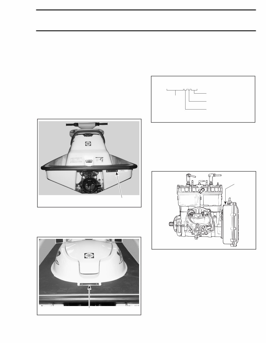
V INTRODUCTION 0 This Shop Manual covers BOMBARDIER made SEA-DOO ® watercraft models SPX 5838/5839, GS 5626/5844, GSX Limited 5629/5845, XP Limit- ed 5665/5667, GTS 5819, GTI 5836/5841and GTX Limited 5837/5842. HULL IDENTIFICATION NUMBER (H.I.N.) SPX and GTS Models It is located at right hand rear side of hull. 1. Hull Identification Number (H.I.N.) All Other Models It is located on floorboard at the rear of the water- craft. 1. Hull Identification Number (H.I.N.) All Models The Hull Identification Number is composed of 9 digits: ENGINE IDENTIFICATION NUMBER (E.I.N.) 717 Engine The Engine Identification Number is located on the upper side of the magneto housing. TYPICAL 1. Engine Identification Number (E.I.N.) F01L8XA 1 F08L0QA 1 Z Z N 1 2 3 4 5 L 4 9 5 Model year Serial number* *A letter may also be used as a digit. F00A0CA Month of production Year of production *A letter may also be used as a digit. 1 F01D01A INTRODUCTION www.SeaDooManuals.net
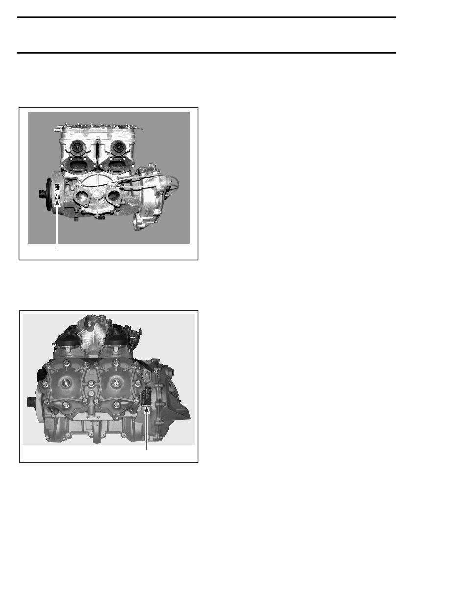
VI 787 Engine The Engine Identification Number is located on the upper crankcase on PTO side. 1. Engine Identification Number (E.I.N.) 947 Engine The Engine Identification Number is located on the upper crankcase on MAGNETO side. 1. Engine Identification Number (E.I.N.) ARRANGEMENT OF THIS MANUAL The manual is divided into 14 major sections: 01 SERVICE TOOLS AND PRODUCTS 02 MAINTENANCE 03 TROUBLESHOOTING 04 ENGINE 05 COOLING SYSTEM 06 FUEL SYSTEM 07 LUBRICATION SYSTEM 08 ELECTRICAL SYSTEM 09 PROPULSION SYSTEM 10 STEERING SYSTEM 11 SUSPENSION 12 HULL/BODY 13 TECHNICAL DATA 14 WIRING DIAGRAMS Several sections are divided in various subsec- tions. There is a table of contents at the beginning of many sections. F01D87A 1 F06D15A 1 INTRODUCTION www.SeaDooManuals.net
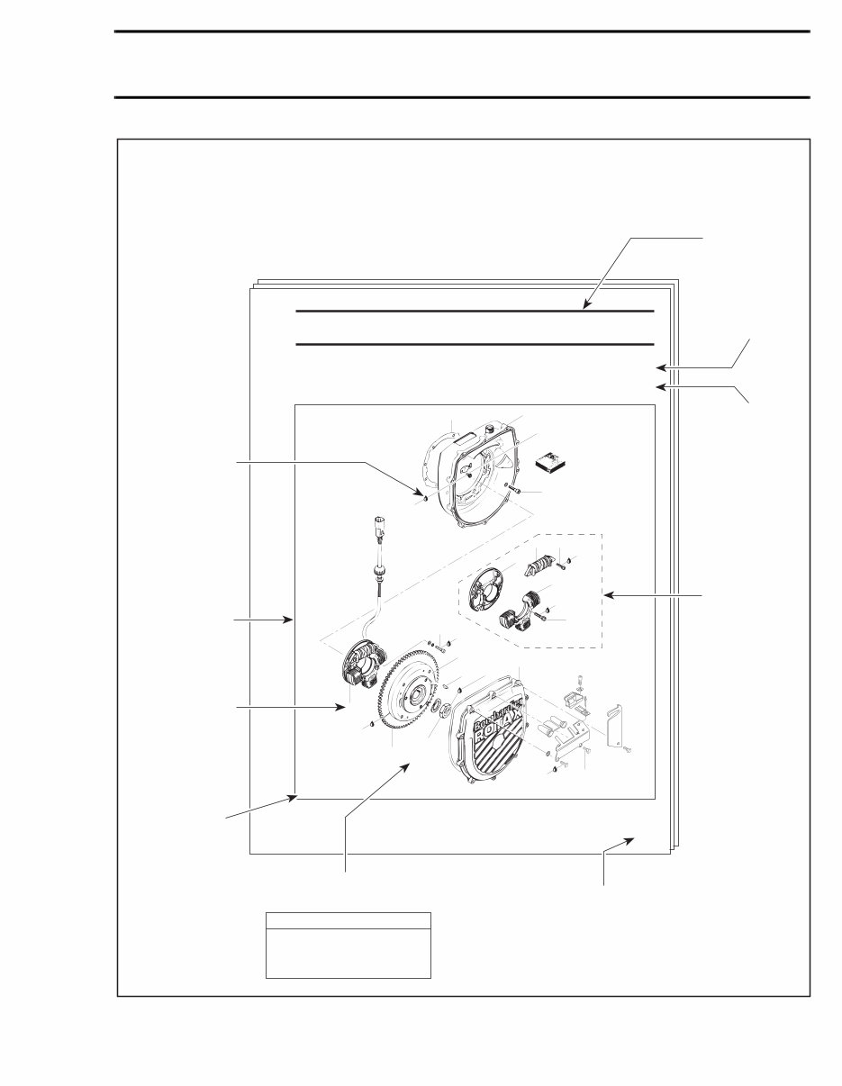
VII Section 03 ENGINE Subsection 04 (MAGNETO SYSTEM) MAGNETO SYSTEM 717 Engine 03-04-1 F01D4WS 12 11 5 N•m (44 lbf•in) 13 9 N•m (80 lbf•in) Loctite 242 4 6 8 Loctite 242 7 6 N•m (53 lbf•in) Loctite 242 6 N•m (53 lbf•in) 9 Loctite 242 5 6 N•m (53 lbf•in) 3 14 Loctite 242 4 Loctite 648 10 15 145 N•m (107 lbf•ft) Anti-seize lubricant 2 9 N•m (80 lbf•in) 1 Page heading indicates section and subsection detailed. Tightening torque nearby fastener. In this case, nut must be torqued to 145 N•m (107 lbf•ft). Exploded view assits you in identifying parts and related positions. TYPICAL PAGE F01A09S Illustration number for publishing process. Subsection title indicates beginning of the subsection. Dotted box contains parts of a particular model or an exploded view. Page numbering system: 03: ENGINE section 04: MAGNETO SYSTEM subsection 1: First page of this subsection Italic sub-title above exploded view indicate pertaining models. Drop represents a liquid product to be applied to a surface. In this case Loctite 242 to screw threads. Bold face number indicates special procedure concerning this part. Pay attention to torque specifi- cations. Some of these are in lbf•in instead of lbf•ft. Use appro- priate torque wrench. CAUTION ▼ INTRODUCTION www.SeaDooManuals.net
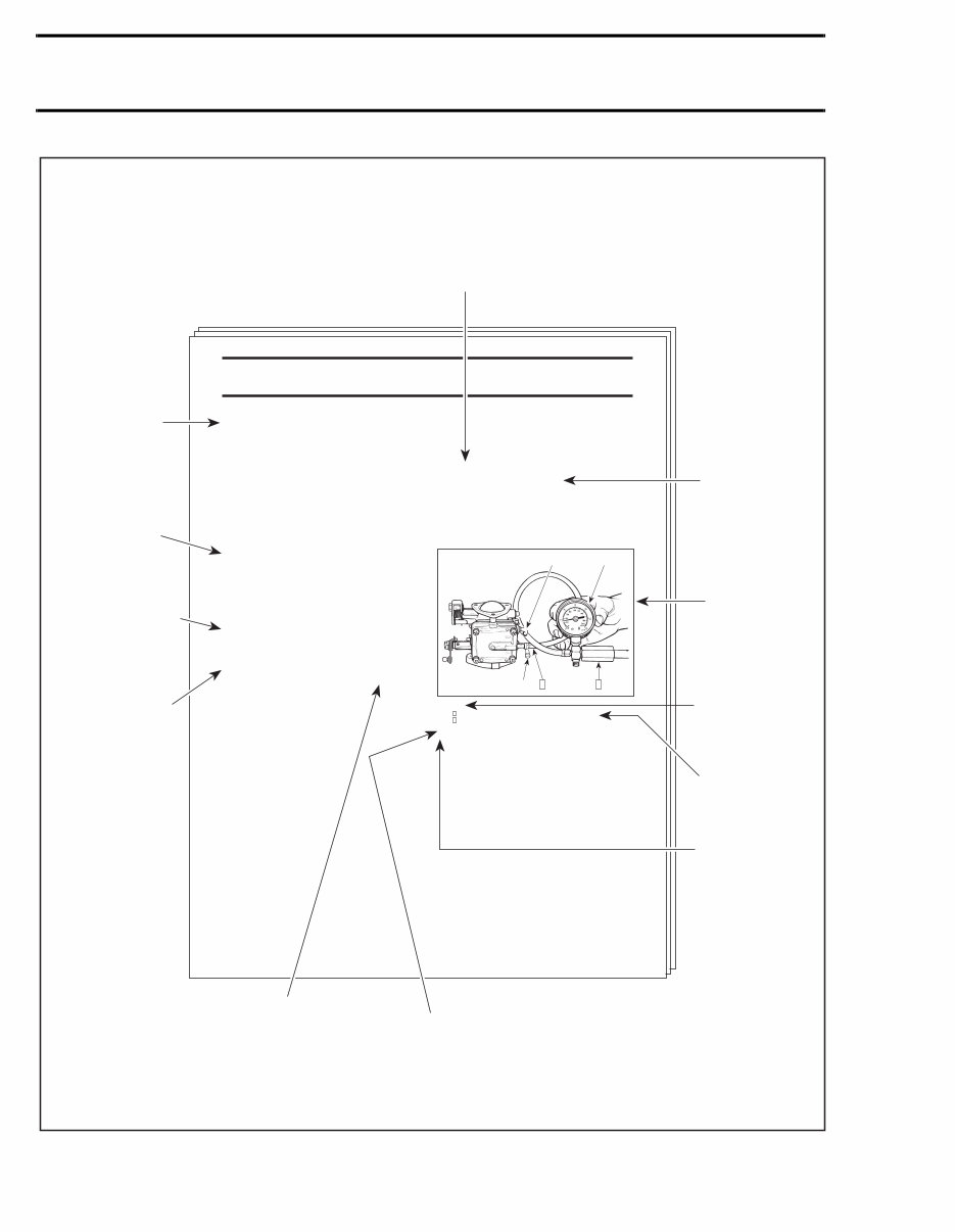
VIII 1 2 Section 06 FUEL SYSTEM Subsection 03 (CARBURETORS) 06-03-4 Step : Install pump gauge tester to pulse nipple Step : Pump tester until it reaches the desired pressure 1. Fuel outlet nipple 2. Fuel inlet nipple A. 28 kPa (4 PSI) 3, Diaphragm XP Model Only CARBURETOR REMOVAL Inspect parts for corrosion dammage (shaft, butterfly, spring screw, check valve housing, etc.). PUMP DIAPHRAGM LEAK TEST TYPICAL To remove carburetors from engine, proceed as fol- lows: Remove air vent tube support. Unlock retaining slides holding air intake silencer base. Remove air intake silencer base from watercraft. Remove screws holding flame arrester base support to cylinder head cover. Unscrew base retaining screws then remove base from carburetors and move to front of watercraft. Turn the valve to OFF position. NOTE: For fuel line removal, use pliers (P/N 295 000 054). Disconnect pulse line from fuel pump. Disconnect fuel fuel supply line from fuel pump. Disconnect fuel return line. Disconnect oil injection pump cable, throttle cable and choke cable. Remove screws no. 6 and lock washers no. 7 retaining carburetors. All Others Models Remove 4 bolts no. 8 and lock washers no. 12 from rotary valve cover then move carburetors and rotary valve cover on top of engine. NOTE: When removing rotary valve cover , pay attention that the rotary valve stay in place, other-wise it must be timed. Remove carburetors from intake manifold. Disconnect fuel bypass line between carburetors (twin carburetors). Remove carburetor(s) from rotary valve cover. DISASSEMBLY AND INSPECTION Using a suitable pump gauge tester, perform the fol- lowing test proceeding as follows: - Install pump gauge tester (P/N 295 000 083) on pulse nipple. - Pump tester until it reaches 28 kPa (4 PSI). Diaphragm must stand pressure for 10 seconds. If pressure drops, replace diaphragm. TYPICAL PAGE Sub-title with part number(s) from exploded view followed by part name(s). "TYPICAL" mention indicates a general view which does not represent full detail. Sub-sub-title in this case indicates that particular procedure for XP is finished, so from this point, all others models are concerned. Title in italic indicates a particular procedure concerning a model. Service tool to be used to perform a certain procedure. Title indicates main procedure to be carried-out. F01A0AS Sub-sub-title in capital indicates a particular testing, adjustment or repair procedure. Illustration always follows text it is pertained to. Numbers in a frame are used to give a sequence to be perfomed. Numbers are used for description of components. Letters are used for any measures. F01F0XB A 2 1 1 2 Bold numbers in the text refer to the parts shown in the exploded view at the beginning of the subsection. INTRODUTION www.SeaDooManuals.net
Get instant access to the Complete Factory Service Repair Workshop Manual without any extra fees or expiry dates. This Professional Manual is suitable for both professional Mechanics and Technicians, as well as DIY enthusiasts. It covers all repairs, servicing, and troubleshooting procedures with highly detailed step-by-step instructions, exploded diagrams, and pictures. The manual is compatible with all Windows and MAC computers and can be accessed on multiple devices without any limitations or trial periods. You have the flexibility to print out a single page or the entire manual as per your requirement. There's no need to worry about renewal fees or expiration, as this is the FULL Manual that can be used for life. Click the button to get started.