

Sea-Doo Challenger 1800 1997 Service Repair Manual
What's Included?
Fast Download Speeds
Online & Offline Access
Access PDF Contents & Bookmarks
Full Search Facility
Print one or all pages of your manual


1997
Shop Manual
Volume 2
Speedster, Challenger/1800
R
219 100 059

Legal deposit:
National Library of Quebec
1
st
trimester 1997
National Library of Canada
All rights reserved. No parts of this manual may be repro-
duced in any form without the prior written permission of
Bombardier Inc.
©
Bombardier Inc. 1997
Printed in Canada
®
*Registered trademarks of Bombardier Inc.
Loctite
®
is a trademark of Corporation.
Snap-on
®
is a trademark of Snap-on Tools Corporation.
Gelcote
®
is a trademark of Gelcote International Limited.

I
SECTION SUB-SECTION PAGE
SAFETY NOTICE .................................................................................................................................. III
INTRODUCTION ................................................................................................................................... IV
01 MAINTENANCE 01 – Table of Contents ..................................................................... 01-01-1
02 – Periodic Inspection Chart ......................................................... 01-02-1
03 – Flushing and Care ..................................................................... 01-03-1
04 – Water-Flooded Engine .............................................................. 01-04-1
05 – Storage ..................................................................................... 01-05-1
02 TROUBLESHOOTING ................................................................................................................ 02-01-1
03 ENGINE 01 – Table of Contents ..................................................................... 03-01-1
02 – Leak Test .................................................................................. 03-02-1
03 – Removal and Installation .......................................................... 03-03-1
04 – Magneto System...................................................................... 03-04-1
05 – Top End .................................................................................... 03-05-1
06 – Bottom End .............................................................................. 03-06-1
07 – Rotary Valve ............................................................................. 03-07-1
08 – Exhaust System ....................................................................... 03-08-1
04 COOLING SYSTEM 01 – Table of Contents ..................................................................... 04-01-1
02 – Components ............................................................................. 04-02-1
03 – Circuit ....................................................................................... 04-03-1
05 FUEL SYSTEM 01 – Table of Contents ..................................................................... 05-01-1
02 – Fuel Circuit ............................................................................... 05-02-1
03 – Air Intake .................................................................................. 05-03-1
04 – Carburetors............................................................................... 05-04-1
06 LUBRICATION
SYSTEM
01 – Table of Contents ..................................................................... 06-01-1
02 – Oil Injection Reservoir .............................................................. 06-02-1
03 – Oil Injection Pump .................................................................... 06-03-1
07 ELECTRICAL 01 – Table of Contents ..................................................................... 07-01-1
02 – Overview .................................................................................. 07-02-1
03 – Ignition System ........................................................................ 07-03-1
04 – Spark Plugs............................................................................... 07-04-1
05 – The DESS (Digitally Encoded Security System) ....................... 07-05-1
06 – MPEM (Multi-Purpose Electronic Module) ............................... 07-06-1
07 – Charging System ...................................................................... 07-07-1
08 – Starting System........................................................................ 07-08-1
09 – Instruments and Accessories ................................................... 07-09-1
TABLE OF CONTENTS

II
SECTION SUB-SECTION PAGE
08 PROPULSION AND
DRIVE SYSTEMS
01 – Table of Contents..................................................................... 08-01-1
02 – Jet Pump.................................................................................. 08-02-1
03 – Drive System ........................................................................... 08-03-1
04 – Reverse System....................................................................... 08-04-1
05 – Weedless System.................................................................... 08-05-1
06 – Variable Trim System (VTS)...................................................... 08-06-1
09 STEERING SYSTEM 01 – Table of Contents..................................................................... 09-01-1
02 – Steering System ...................................................................... 09-02-1
03 – Alignment................................................................................. 09-03-1
04 – Throttle/Shifter/VTS Controller ................................................. 09-04-1
10 HULL/DECK 01 – Table of Contents..................................................................... 10-01-1
02 – Components ............................................................................ 10-02-1
03 – Hull and Deck Repair................................................................ 10-03-1
04 – Painting .................................................................................... 10-04-1
11 TECHNICAL DATA ..................................................................................................................... 11-01-1
12 WIRING DIAGRAMS.................................................................................................................. 12-01-1
TABLE OF CONTENTS
III
SAFETY NOTICE
This manual was primarily published to be used by jet boat technicians trained by the manufacturer who
are already familiar with all service and maintenance procedures relating to Bombardier made Sea-Doo
jet boat.
Please note that the instructions will apply only if proper hand tools and special service tools are used.
It is understood that this manual may be translated into local language upon certain conditions and fur-
thermore agreed that in the event of any discrepancy among the two versions, the English version shall
prevail.
The content depicts parts and/or procedures applicable to the particular product at its time of manufac-
ture. It does not include dealer modifications, whether authorized or not by Bombardier, after manufac-
turing the product.
The use of Bombardier parts is most strongly recommended when considering replacement of any com-
ponent. Dealer and/or distributor assistance should be sought in case of doubt.
Torque wrench tightening specifications must be strictly adhered to. Locking devices (ex.: locking disk,
lock nut) must be installed or replaced with new ones, where specified. If the efficiency of a locking
device is impaired, it must be renewed.
This manual emphasizes particular information denoted by the wording and symbols:
NOTE: Indicates supplementary information needed to fully complete an instruction.
Although the mere reading of such information does not eliminate the hazard, your understanding of the
information will promote its correct use. Always use common shop safety practice.
This information relates to the preparation and use of Bombardier jet boat and has been utilized safely
and effectively by Bombardier Inc. However, Bombardier Inc. disclaims liability for all damages and/or
injuries resulting from the improper use of the contents. We strongly recommend that any services be
carried out and/or verified by a highly skilled professional technician. It is understood that certain modifi-
cations may render use of the boat illegal under existing federal, provincial and state regulations.
◆
WARNING
Identifies an instruction which, if not followed, could cause serious personal injury including
possibility of death.
-
CAUTION
Denotes an instruction which, if not followed, could severely damage boat components.
SAFETY NOTICE
IV
INTRODUCTION
This Shop Manual covers the following BOMBAR-
DIER made SEA-DOO
®
jet boats.
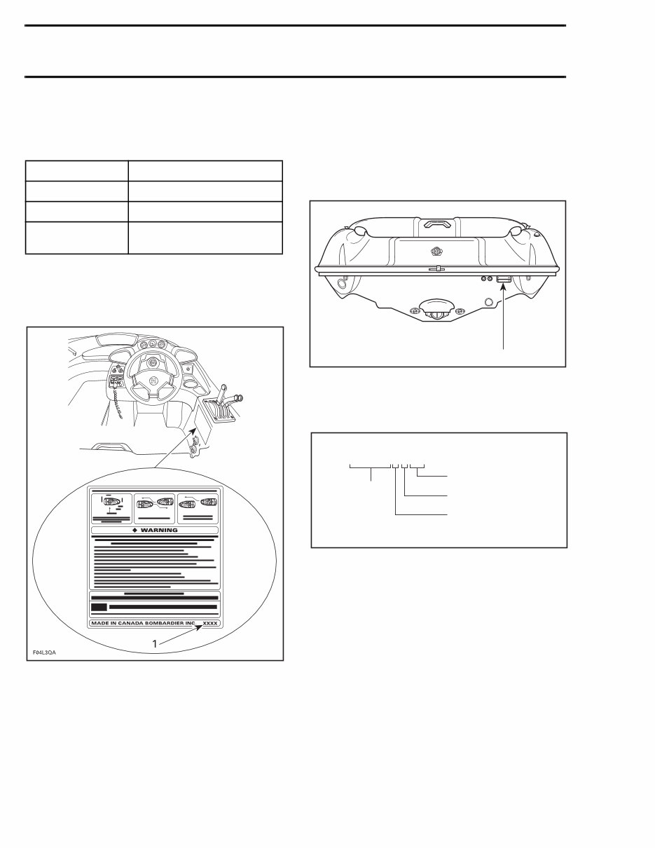
BOAT MODEL NUMBER
The jet boat model number can be found on RH
side of operator position.
TYPICAL
1. Model number
HULL IDENTIFICATION NUMBER
(H.I.N.)
The Hull Identification Number (H.I.N.) is located
at right hand rear side of hull.
TYPICAL
1. Hull Identification Number (H.I.N.)
Refer to the illustration for a description of the se-
rial number.
Some boats may have a serial number beginning
with CEC. CEC boats are manufactured in USA
and ZZN boats are manufactured in Canada.
MODEL MODEL NUMBER
SPEEDSTER 5602/5608
CHALLENGER 5603/5606
CHALLENGER
1800
5600/5601
F04L2SB
1
Z Z N 1 2 3 4 5 L 4 9 5
Model year
Serial
number*
*A letter may also be used as a digit.
F00A0CA
Month of production
Year of production
*A letter may also be used as a digit.
1997 BOMBARDIER JET BOAT
SHOP MANUAL
V
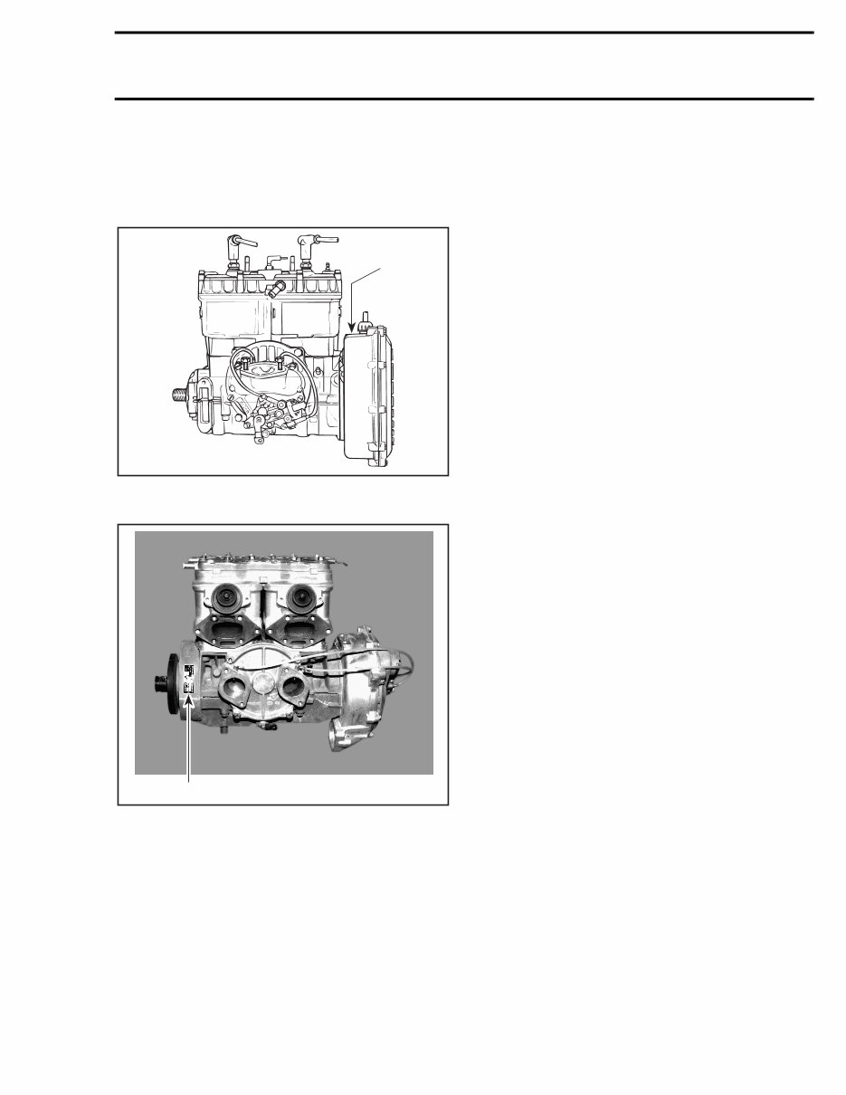
ENGINE IDENTIFICATION
NUMBER (E.I.N.)
It is located on the upper side of the magneto
housing.
TYPICAL — 717 ENGINE
1. Engine Identification Number (E.I.N.)
787 ENGINE
1. Engine Identification Number (E.I.N.)
ARRANGEMENT OF THIS
MANUAL
The manual is divided into 12 major sections:
01 MAINTENANCE
02 TROUBLESHOOTING
03 ENGINE
04 COOLING SYSTEM
05 FUEL SYSTEM
06 LUBRICATION SYSTEM
07 ELECTRICAL
08 PROPULSION SYSTEM
09 STEERING SYSTEM
10 HULL/DECK
11 TECHNICAL DATA
12 WIRING DIAGRAMS
Each section is divided in various sub-sections,
and again, each sub-section has one or more divi-
sion. A table of contents is included at the begin-
ning of most sections.
1
F01D01A
F01D87A
1
1997 BOMBARDIER JET BOAT
SHOP MANUAL
VI
Section 03 ENGINE
Sub-Section 04 (MAGNETO SYSTEM)
MAGNETO SYSTEM
717 Engine
03-04-1
F01D4WS
12 11
5 N•m
(44 lbf•in)
13
9 N•m
(80 lbf•in)
Loctite
242
4
6 8
Loctite
242
7
6 N•m
(53 lbf•in)
Loctite
242
6 N•m
(53 lbf•in)
9
Loctite
242
5
6 N•m
(53 lbf•in)
3
14
Loctite
242
4
Loctite
648
10
15
145 N•m
(107 lbf•ft)
Anti-seize
lubricant
2
9 N•m
(80 lbf•in)
1
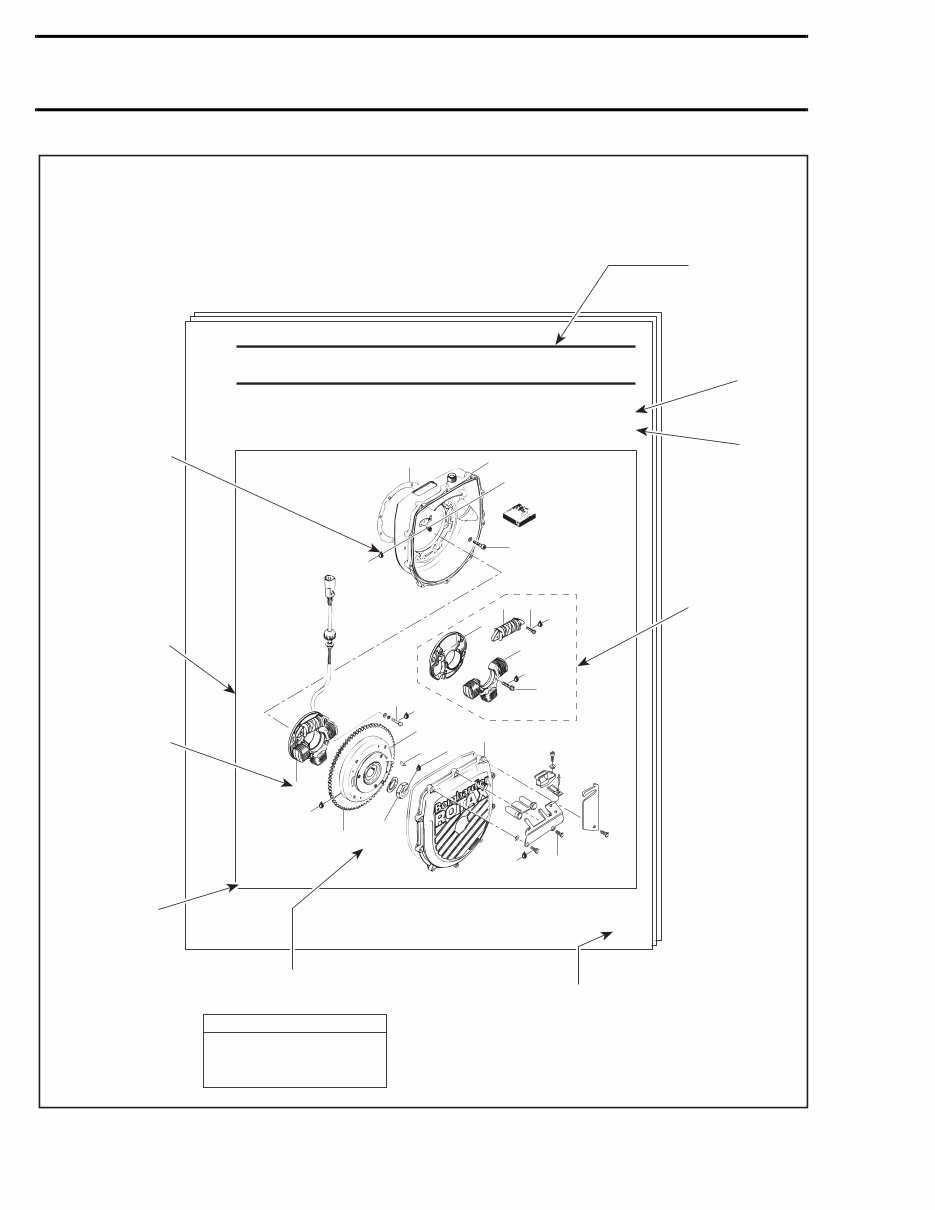
Page heading
indicates section
and sub-section
detailed.
Tightening torque nearby fastener.
In this case, nut must be torqued to
145 N•m (107 lbf•ft).
Exploded view assists
you in identifying
parts and related
positions.
TYPICAL PAGE
F04A09S
Illustration number
for publishing
process.
Sub-section title
indicates
beginning of the
sub-section.
Dotted box
contains parts of
a particular
model or an
exploded view.
Page numbering system:
03: ENGINE section
04: MAGNETO SYSTEM sub-section
1: First page of this sub-section
Italic sub-title
above exploded
view indicate
pertaining models.
Drop represents a
liquid product to be
applied to a surface.
In this case Loctite
242 to screw
threads.
Bold face number
indicates special
procedure
concerning this part.
Pay attention to torque specifi-
cations. Some of these are in
lbf•in instead of lbf•ft. Use appro-
priate torque wrench.
CAUTION ▼
1997 BOMBARDIER JET BOAT
SHOP MANUAL
VII
1
2
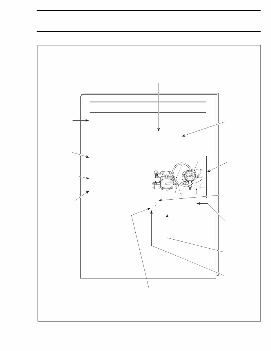
Section 06 FUEL SYSTEM
Sub-Section 03 (CARBURETORS)
06-03-4
Step : Install pump gauge tester to pulse nipple
Step : Pump tester until it reaches the desired pressure
1. Fuel outlet nipple
2. Fuel inlet nipple
A. 28 kPa (4 PSI)
Diaphragm
Challenger Model Only
CARBURETOR REMOVAL
Inspect parts for corrosion dammage (shaft, butterfly,
spring screw, check valve housing, etc.).
Pump Diaphragm Leak Test
TYPICAL
To remove carburetors from engine, proceed as fol-
lows:
Remove air vent tube support.
Unlock retaining slides holding air intake silencer base.
Remove air intake silencer base from watercraft.
Remove screws holding flame arrester base support
to cylinder head cover.
Unscrew base retaining screws then remove base from
carburetors and move to front of watercraft.
Turn the valve to OFF position.
NOTE: For fuel line removal, use pliers (P/N 295 000
054).
Disconnect pulse line from fuel pump.
Disconnect fuel fuel supply line from fuel pump.
Disconnect fuel return line.
Disconnect oil injection pump cable, throttle cable and
choke cable.
Remove screws and lock washers retaining carburetors.
Remove carburetors from intake manifold.
All Others Models
Remove 4 bolts and lock washers from rotary valve
cover then move carburetors and rotary valve cover on
top of engine.
NOTE: When removing rotary valve cover , pay attention
that the rotary valve stay in place, otherwise it must be
timed.
Remove carburetors from intake manifold.
Disconnect fuel bypass line between carburetors (twin
carburetors).
Remove carburetor(s) from rotary valve cover.
DISASSEMBLY AND INSPECTION
Using a suitable pump gauge tester, perform the fol-
lowing test proceeding as follows:
- Install pump gauge tester (P/N 295 000 083) on pulse
nipple.
- Pump tester until it reaches 28 kPa (4 PSI).
Diaphragm no. 3 must stand pressure for 10 seconds.
If pressure drops, replace diaphragm.
TYPICAL PAGE
Sub-title indicates a
particular procedure for
the named part.
''TYPICAL'' caption
indicates a general
view which does not
represent full detail.
Italic bold face
setting in this case
indicates that
particular procedure
for Challenger is
finished, so from this
point, all others
models are
concerned.
Italic bold face setting
indicates a particular
procedure concerning
a model.
Service tool to be
used to perform a
certain procedure.
Title indicates main
procedure to be
carried-out.
F04A08S
Sub-sub-title
indicates a
particular testing,
adjustment or
repair procedure.
Illustration
always follows
text it is
pertained to.
Numbers in a frame
are used to give a
sequence to be
perfomed for above
illustration.
Numbers are used
for description of
components for
above illustration.
Letters are used for
any measures for
above illustration.
F01F0XB
A
2
1
1 2
Number: following
part name refers to
exploded view at
beginning of
sub-section.
1997 BOMBARDIER JET BOAT
SHOP MANUAL
You're Reading a Preview
What's Included?
Fast Download Speeds
Online & Offline Access
Access PDF Contents & Bookmarks
Full Search Facility
Print one or all pages of your manual
$41.99
Viewed 22 Times Today


Secure transaction
What's Included?
Fast Download Speeds
Online & Offline Access
Access PDF Contents & Bookmarks
Full Search Facility
Print one or all pages of your manual
$41.99
The Sea-Doo Challenger 1800 1997 Service Repair Manual is a comprehensive factory manual designed for the maintenance and repair of the Sea-Doo Challenger 1800 watercraft. It is an invaluable resource for both professional mechanics and DIY enthusiasts.
- Complete and searchable for easy navigation
- Includes detailed information on maintenance, troubleshooting, engine, cooling system, fuel system, lubrication system, electrical components, propulsion and drive system, steering system, hull, technical data, and wiring diagrams
- Available in PDF format
- Language: English
- Compatible with Win/Linux/MAC operating systems
- Instant delivery


