2005
Vehicle Shop Manual
4-TEC Series
www.SeaDooManuals.net
Legal deposit:
National Library of Quebec
National Library of Canada 2005
All rights reserved. No parts of this manual may be reproduced in any form without the prior written
permission of Bombardier Recreational Products Inc. (BRP)
©
Bombardier Recreational Products Inc. (BRP) 2005
Technical Publications
Bombardier Recreational Products Inc. (BRP)
Valcourt (Quebec) Canada
Printed in Canada
®TM
Registered trademarks of Bombardier Recreational Products Inc. (BRP) or its affiliates.
* Trademark of Bombardier Inc. used under license.
SEA-DOO
®
BOMBARDIER-ROTAX
®
BOMBARDIER LUBE
®
Sea-Doo
®
Learning Key
TM
DESS
TM
Rotax
®
O.P.A.S.
TM
TOPS
TM
This document contains the trademarks of the following companies:
Knight’s Spray-Nine
†
is a trademark of Korkay System Ltd
GTX
†
is a trademark of Castrol Ltd. Used under license
Loctite
®
is a trademark of Loctite Corporation
Snap-on
®
is a trademark of Snap-on Tools Corporation
Gelcote
®
is a trademark of Gelcote International Limited
Molykote
©
is a trademark of Dow Corning Corporation
AMP
©
is a trademark of Tyco Electronics Corporation
www.SeaDooManuals.net
TABLE OF CONTENTS
SAFETY NOTICE ................................................................................... VI
INTRODUCTION ................................................................................... VII
GENERAL INFORMATION ......................................................................................... VII
ARRANGEMENT OF THIS MANUAL ........................................................................... VIII
ABBREVIATIONS USED IN THIS MANUAL ................................................................... VIII
ILLUSTRATIONS AND PROCEDURES .......................................................................... IX
ENGINE EMISSIONS INFORMATION ........................................................................... XII
SELF-LOCKING FASTENERS PROCEDURE .................................................................... XII
LOCTITE APPLICATION PROCEDURE .......................................................................... XIII
TIGHTENING TORQUES ......................................................................................... XVI
01 MAINTENANCE
01 – MAINTENANCE CHART ....................................................................................... 1
02 – PRESEASON PREPARATION ................................................................................. 3
03 – STORAGE PROCEDURES ..................................................................................... 5
PROPULSION SYSTEM ............................................................................................... 5
FUEL SYSTEM ......................................................................................................... 5
ENGINE OIL AND FILTER REPLACEMENT ......................................................................... 5
OPENED LOOP COOLING SYSTEM ................................................................................ 5
CLOSED LOOP COOLING SYSTEM (ENGINE) ..................................................................... 8
ENGINE LUBRICATION ............................................................................................... 8
THROTTLE BODY LUBRICATION .................................................................................... 8
ANTIFREEZING PROTECTION ....................................................................................... 8
BATTERY ............................................................................................................... 9
WATERCRAFT CLEANING ............................................................................................ 9
ANTICORROSION TREATMENT ..................................................................................... 9
CHECKLIST ........................................................................................................... 10
04 – SPECIAL PROCEDURES ..................................................................................... 11
TOWING THE WATERCRAFT IN WATER ........................................................................... 11
SUBMERGED WATERCRAFT ....................................................................................... 12
WATER-FLOODED ENGINE ......................................................................................... 12
02 TROUBLESHOOTING
01 – TROUBLESHOOTING CHART .............................................................................. 15
ENGINE WILL NOT START .......................................................................................... 15
ENGINE HARD TO START ........................................................................................... 17
ENGINE STARTS BUT RUNS ONLY AT IDLE SPEED .............................................................. 18
ENGINE MISFIRES, RUNS IRREGULARLY ......................................................................... 18
ENGINE CONTINUALLY BACKFIRES ............................................................................... 19
ENGINE DETONATION OR PINGING ............................................................................... 19
ENGINE LACKS ACCELERATION OR POWER .................................................................... 20
ENGINE STOPS RUNNING .......................................................................................... 20
ENGINE CANNOT REACH MAXIMUM RPM ...................................................................... 21
ENGINE RUNS TOO FAST (VEHICLE CANNOT REACH ITS TOP SPEED) ....................................... 21
ENGINE OVERHEATS ................................................................................................ 22
ENGINE SMOKE IN THE EXHAUST ................................................................................ 22
LOW OR NO ENGINE OIL PRESSURE ............................................................................. 23
ENGINE OIL CONTAMINATION (MILKY) ........................................................................... 23
UNUSUAL ENGINE NOISE AND/OR VIBRATION ................................................................. 24
INAPPROPRIATE SPEEDOMETER READING ..................................................................... 24
ABNORMAL NOISE FROM PROPULSION SYSTEM .............................................................. 24
I
www.SeaDooManuals.net
TABLE OF CONTENTS
03 ENGINE SYSTEM
01 – AIR INTAKE SYSTEM ........................................................................................ 27
INSPECTION .......................................................................................................... 30
REMOVAL ............................................................................................................ 30
INSTALLATION ....................................................................................................... 31
02 – LUBRICATION SYSTEM ..................................................................................... 33
GENERAL ............................................................................................................. 33
OIL LEVEL VERIFICATION ........................................................................................... 33
OIL CHANGE ......................................................................................................... 34
OIL TYPE AND SYSTEM CAPACITY ................................................................................ 35
OIL FILTER ............................................................................................................ 35
03 – COOLING SYSTEM .......................................................................................... 37
CLOSED LOOP COOLING SYSTEM (ENGINE) .......................................................... 38
CIRCUIT ............................................................................................................... 39
COOLING SYSTEM LEAK TEST ..................................................................................... 39
INSPECTION .......................................................................................................... 40
COOLANT REPLACEMENT ......................................................................................... 40
CARE .................................................................................................................. 42
TECHNICAL SPECIFICATIONS ...................................................................................... 42
OPENED LOOP COOLING SYSTEM (EXHAUST SYSTEM) ............................................ 43
CIRCUIT ............................................................................................................... 45
CARE .................................................................................................................. 46
TECHNICAL SPECIFICATIONS ...................................................................................... 47
04 – EXHAUST SYSTEM .......................................................................................... 49
EXHAUST PIPE ....................................................................................................... 51
EXHAUST MANIFOLD ............................................................................................... 54
MUFFLER ............................................................................................................. 55
RESONATOR ......................................................................................................... 56
EXHAUST OUTLET ................................................................................................... 56
05 – REMOVAL AND INSTALLATION ........................................................................... 59
ENGINE REMOVAL .................................................................................................. 59
CLEANING ............................................................................................................ 63
INSTALLATION ....................................................................................................... 63
04 ENGINE MANAGEMENT (1503 4-TEC)
01 – OVERVIEW .................................................................................................... 67
OPERATING PRINCIPLE ..................................................................................... 68
AIR INDUCTION ...................................................................................................... 68
FUEL SYSTEM ........................................................................................................ 70
ELECTRICAL SYSTEM ............................................................................................... 70
ENGINE MANAGEMENT SYSTEM (EMS) ............................................................... 72
EMS — ENGINE MANAGEMENT SYSTEM FUNCTIONS ......................................................... 74
02 – DIAGNOSTIC PROCEDURES ............................................................................... 79
GENERAL ............................................................................................................. 79
SELF-DIAGNOSTIC MODE .......................................................................................... 81
ENGINE MANAGEMENT SYSTEM FAULT CODES ................................................................ 82
VCK (VEHICLE COMMUNICATION KIT) .......................................................................... 105
03 – COMPONENT INSPECTION, REPLACEMENT AND ADJUSTMENT ................................ 107
GENERAL ..................................................................................................... 107
FUEL SYSTEM ...................................................................................................... 107
ELECTRICAL SYSTEM ............................................................................................. 108
TESTING PROCEDURES ................................................................................... 111
II
www.SeaDooManuals.net
TABLE OF CONTENTS
IDLE SPEED ........................................................................................................ 111
IGNITION TIMING .................................................................................................. 111
SAFETY LANYARD SWITCH VERIFICATION ..................................................................... 111
ECM AND MPEM .................................................................................................. 112
ENGINE WIRING HARNESS ....................................................................................... 113
FUEL INJECTOR ................................................................................................... 115
THROTTLE BODY .................................................................................................. 117
THROTTLE POSITION SENSOR (TPS) ............................................................................ 120
IDLE BYPASS VALVE ............................................................................................... 122
CRANKSHAFT POSITION SENSOR (CPS) ........................................................................ 122
CAMSHAFT POSITION SENSOR (CAPS) ......................................................................... 123
MANIFOLD AIR TEMPERATURE SENSOR (MATS) ............................................................. 124
COOLANT TEMPERATURE SENSOR (CTS) ...................................................................... 125
MANIFOLD AIR PRESSURE SENSOR (MAPS) .................................................................. 125
EXHAUST GAS TEMPERATURE SENSOR (EGTS) ............................................................... 126
KNOCK SENSOR (KS) .............................................................................................. 127
OIL PRESSURE SENSOR (OPS) .................................................................................. 128
TOPS VALVE ........................................................................................................ 128
OIL SEPARATOR PRESSURE SENSOR (OSPS) ................................................................. 129
TOPS SWITCH ...................................................................................................... 130
05 FUEL SYSTEM
01 – FUEL TANK AND FUEL PUMP ............................................................................ 133
GENERAL ........................................................................................................... 135
REMOVAL .......................................................................................................... 136
INSPECTION ........................................................................................................ 137
INSTALLATION ..................................................................................................... 139
TESTING PROCEDURES .......................................................................................... 140
06 ELECTRICAL SYSTEM
01 – IGNITION SYSTEM ......................................................................................... 145
GENERAL ........................................................................................................... 147
QUICK TEST WITH B.U.D.S ....................................................................................... 147
VOLTAGE TEST ..................................................................................................... 147
IGNITION COIL ..................................................................................................... 148
SPARK PLUGS ...................................................................................................... 149
IGNITION TIMING ................................................................................................. 149
02 – CHARGING SYSTEM ....................................................................................... 151
GENERAL ..................................................................................................... 153
TESTING PROCEDURE ..................................................................................... 153
RECTIFIER/REGULATOR .......................................................................................... 154
STATOR ............................................................................................................. 155
BATTERY ............................................................................................................ 157
03 – STARTING SYSTEM ........................................................................................ 163
STARTING SYSTEM TROUBLESHOOTING ...................................................................... 166
GENERAL ........................................................................................................... 167
STARTER REMOVAL ............................................................................................... 168
STARTER DISASSEMBLY .......................................................................................... 168
STARTER CLEANING .............................................................................................. 169
STARTER INSPECTION ............................................................................................ 170
STARTER ASSEMBLY .............................................................................................. 170
STARTER INSTALLATION ......................................................................................... 170
III
www.SeaDooManuals.net
TABLE OF CONTENTS
STARTER SPECIFICATION ........................................................................................ 171
04 – INSTRUMENTS AND ACCESSORIES .................................................................... 173
GENERAL ........................................................................................................... 173
COMPONENT DESCRIPTION ..................................................................................... 173
PROCEDURES ...................................................................................................... 177
07 PROPULSION
01 – JET PUMP .................................................................................................... 183
GENERAL ........................................................................................................... 186
JET PUMP INSPECTION ON WATERCRAFT ..................................................................... 186
REMOVAL .......................................................................................................... 187
DISASSEMBLY ..................................................................................................... 190
CLEANING .......................................................................................................... 193
PARTS INSPECTION ............................................................................................... 193
ASSEMBLY ......................................................................................................... 194
PUMP PRESSURIZATION ......................................................................................... 199
INSTALLATION ..................................................................................................... 199
02 – DRIVE SYSTEM .............................................................................................. 203
GENERAL ........................................................................................................... 205
REMOVAL .......................................................................................................... 205
INSPECTION ........................................................................................................ 208
INSTALLATION ..................................................................................................... 209
LUBRICATION ...................................................................................................... 213
03 – REVERSE SYSTEM ......................................................................................... 215
DISASSEMBLY ..................................................................................................... 217
INSPECTION ........................................................................................................ 219
ASSEMBLY ......................................................................................................... 219
ADJUSTMENT ...................................................................................................... 219
04 – VARIABLE TRIM SYSTEM ................................................................................. 221
GENERAL ........................................................................................................... 223
REMOVAL .......................................................................................................... 223
DISASSEMBLY ..................................................................................................... 223
INSPECTION ........................................................................................................ 224
ASSEMBLY ......................................................................................................... 224
INSTALLATION ..................................................................................................... 224
ADJUSTMENT ...................................................................................................... 225
08 STEERING SYSTEM
01 – STEERING SYSTEM ........................................................................................ 227
DISASSEMBLY ..................................................................................................... 229
ASSEMBLY ......................................................................................................... 234
ALIGNMENT ........................................................................................................ 236
02 – OFF-POWER ASSISTED STEERING SYSTEM (O.P.A.S.) .............................................. 239
GENERAL ........................................................................................................... 242
SIDE VANE .......................................................................................................... 242
CYLINDER SUPPORT .............................................................................................. 243
TIE ROD ............................................................................................................. 246
SEALED TUBE ...................................................................................................... 246
FILTER ............................................................................................................... 247
VALVE ............................................................................................................... 247
WATER HOSE ...................................................................................................... 248
CROSS SUPPORT PLATE ......................................................................................... 248
IV
www.SeaDooManuals.net
TABLE OF CONTENTS
09 HULL/BODY
01 – ADJUSTMENT AND REPAIR .............................................................................. 251
GENERAL ........................................................................................................... 262
GLOVE BOX ........................................................................................................ 262
ENGINE COVER .................................................................................................... 263
SEAT ADJUSTMENT ............................................................................................... 263
STORAGE COMPARTMENT INNER SHELL ..................................................................... 264
STORAGE COVER SHOCK ........................................................................................ 269
STORAGE COMPARTMENT COVER ADJUSTMENT ........................................................... 270
MIRROR ............................................................................................................ 270
CLUSTER ........................................................................................................... 271
DEFLECTOR AND/OR UPPER GRID .............................................................................. 271
SIDE MOLDING .................................................................................................... 272
INLET GRATE ....................................................................................................... 272
RIDING PLATE ...................................................................................................... 273
JET PUMP SUPPORT .............................................................................................. 274
DRAIN PLUG INSTALLATION ..................................................................................... 275
SEAT COVER REPLACEMENT .................................................................................... 276
BUMPER REPLACEMENT ......................................................................................... 276
WAKE PYLON ...................................................................................................... 276
SPONSON REPLACEMENT ....................................................................................... 278
SPONSON ADAPTOR .............................................................................................. 278
BAILER PICK-UPS INSPECTION .................................................................................. 278
DECALS REPLACEMENT .......................................................................................... 279
HULL AND BODY REPAIR ......................................................................................... 280
TOOLS AND MATERIALS LIST ................................................................................... 282
10 TECHNICAL SPECIFICATIONS
01 – GTX, WAKE AND GTX SC MODELS ..................................................................... 283
02 – GTX LIMITED AND RXT MODELS ........................................................................ 287
03 – RXP MODELS ................................................................................................ 291
11 ELECTRICAL CONNECTORS AND WIRING DIAGRAMS
01 – ELECTRICAL CONNECTORS .............................................................................. 295
DEUTSCH CONNECTORS ......................................................................................... 295
PACKARD CONNECTOR .......................................................................................... 298
AMP CONNECTOR ................................................................................................ 298
ECM CONNECTORS ............................................................................................... 302
BATTERY AND STARTER CABLE TERMINALS .................................................................. 305
02 – WIRING DIAGRAMS ........................................................................................ 307
WIRE COLOR CODES ............................................................................................. 307
WIRE DIGIT CODES ............................................................................................... 307
V
www.SeaDooManuals.net
SAFETY NOTICE
SAFETY NOTICE
This manual has been prepared as a guide to correctly service and repair 2005 SEA-DOO watercraft as
describe in the model list in the INTRODUCTION.
This edition was primarily published to be used by watercraft mechanical technicians who are already fa-
miliar with all service procedures relating to BRP made watercraft. Mechanical technicians should attend
training courses given by BRP Training Dept.
Please note that the instructions will apply only if proper hand tools and special service tools are used.
This VEHICLE SHOP MANUAL uses technical terms which may be slightly different from the ones used
in the Parts Catalog.
It is understood that this manual may be translated into another language. In the event of any discrepan-
cy, the English version shall prevail.
The content depicts parts and/or procedures applicable to the particular product at time of writing. Ser-
vice and Warranty Bulletins may be published to update the content of this manual. Make sure to read
and understand these.
In addition, the sole purpose of the illustrations throughout the manual, is to assist identification of the
general configuration of the parts. They are not to be interpreted as technical drawings or exact replicas
of the parts.
The use of BRP parts is most strongly recommended when considering replacement of any component.
Dealer and/or distributor assistance should be sought in case of doubt.
The engines and the corresponding components identified in this document should not be utilized on
product(s) other than those mentioned in this document.
WARNING
Unless otherwise specified, engine should be turned OFF and cold for all maintenance and repair
procedures.
This manual emphasizes particular information denoted by the wording and symbols:
WARNING
Identifies an instruction which, if not followed, could cause serious personal injury including pos-
sibility of death.
CAUTION: Denotes an instruction which, if not followed, could severely damage vehicle compo-
nents.
NOTE: Indicates supplementary information needed to fully complete an instruction.
Although the mere reading of such information does not eliminate the hazard, your understanding of the
information will promote its correct use. Always use common shop safety practice.
BRP disclaims liability for all damages and/or injuries resulting from the improper use of the contents.
We strongly recommend that any services be carried out and/or verified by a highly skilled professional
mechanic. It is understood that certain modifications may render use of the vehicle illegal under existing
federal, provincial and state regulations.
VI
smr2005-002
www.SeaDooManuals.net
INTRODUCTION
INTRODUCTION
GENERAL INFORMATION
This VEHICLE SHOP MANUAL covers the following BRP made SEA-DOO
®
2005 watercraft models. It
should be used in conjunction with the 1503 4-TEC ENGINE SHOP MANUAL .
MODEL COLOR ENGINE MODEL NUMBER
GTX Twilight Blue Pearl 1503 Naturally Aspirated 145A, 145B
GTX Limited Midnight Black Pearl 1503 Supercharged Intercooled 185A, 185B
GTX Supercharged Twilight Blue Pearl 1503 Supercharged 165A
RXP Apple Green 1503 Supercharged Intercooled 215A, 215B
RXP Viper Red Metallic 1503 Supercharged Intercooled 215C, 215D
RXT Apple Green 1503 Supercharged Intercooled 175A, 175B
RXT Viper Red Metallic 1503 Supercharged Intercooled 175C, 175D
WAKE Viper Red 1503 Naturally Aspirated 155A, 155B
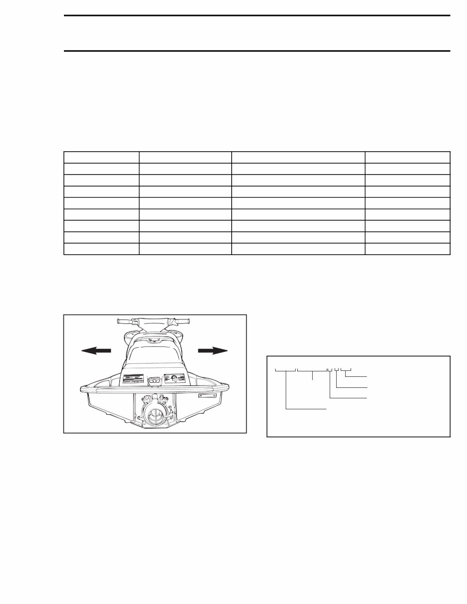
The use of RIGHT (starboard) and LEFT (port) indi-
cations in the text, always refers to driving position
(when sitting on watercraft).
Besides, in the marine industry, FRONT is called
BOW and REAR is called STERN.
F01L45B
1 2
1. Left (port)
2. Right (starboard)
The information and component/system descrip-
tions contained in this manual are correct at time
of writing. BRP however, maintains a policy of
continuous improvement of its products without
imposing upon itself any obligation to install them
on products previously manufactured.
BRP reserves the right at any time to discontinue
or change specifications, designs, features, mod-
els or equipment without incurring obligation.
This VEHICLE SHOP MANUAL uses technical
terms which may be different from the ones of
the PARTS CATALOGS .
When ordering parts always refer to the specific
model PARTS CATALOGS .
Hull Identification Number (H.I.N.)
The Hull Identification Number is composed of 12
digits:
smr05-002-001_aen
smr2005-002 VII
www.SeaDooManuals.net
You're Reading a Preview
What's Included?
Lifetime Access
Access PDF Contents & Bookmarks
Print one or all pages of your manual