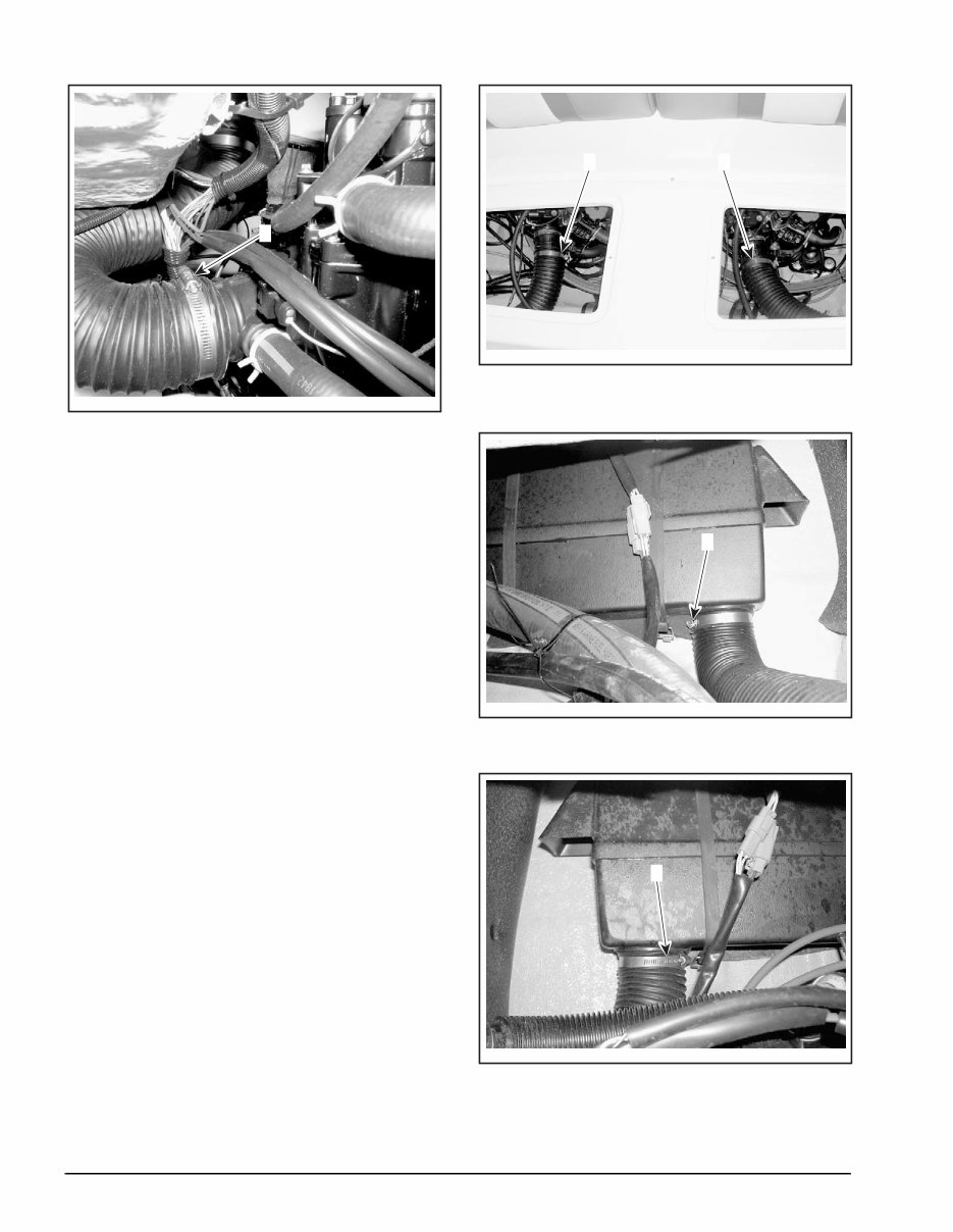
Page 2 of 4 2004-1 TYPICAL — SPORTSTER 4-TEC 1. Loosen this clamp and remove air intake hose from engine fitting Remove original hose from engine compartment. Put retained clamps onto and install new intake hose. Tighten clamps until hose is firmly secured. Reinstall engine access cover tray and close en- gine compartment cover. Speedster 200 The Speedster 200 will require two pieces cut, one each to replace the existing port and starboard air intake hoses. Cut the port hose to 1020 mm (40.2 in). Cut the starboard hose to 930 mm (36.6 in). Open engine compartment cover. Remove engine access cover tray. Lift and remove rear seat cushions. Remove two screws from each storage tub and remove both storage tubs. Loosen clamps and remove air intake hoses from each engine and air box fitting. Save clamps for reinstallation. TYPICAL — SPEEDSTER 200 1. Loosen this clamp and remove hose from starboard engine fitting 2. Loosen this clamp and remove hose from port engine fitting TYPICAL — PORT AIR BOX 1. Loosen this clamp and remove hose from port air box TYPICAL — STARBOARD AIR BOX 1. Loosen this clamp and remove hose from starboard air box
2004-1 Page 3 of 4 Remove original hoses from engine compart- ment. Put clamps onto new 1020 mm (40.2 in) port in- take hose and install. Put clamps onto new 930 mm (36.6 in) starboard intake hose and install. Tighten clamps until each hose end is firmly se- cured. Reinstall storage tubs and replace cushions. Reinstall engine access cover tray. Close engine compartment cover. WARRANTY Submit a warranty claim using the following infor- mation: For models 5768 and 5770 Sportster 4-TEC For model 5773 Speedster 200 For claiming procedure, refer to the Dealer/Distributor Warranty Guide. Do not return parts. Retain per Warranty Guide. Submit a warranty claim on the BOSSWeb™ web- site or on a Campaign Claim Form (P/N 484 070 300). If a paper warranty claim is used, send claim to: USA DEALERS Shipping address is: Bombardier Recreational Products 7575 Bombardier Court Wausau, WI 54401 ATTN: WARRANTY CANADIAN DEALERS Shipping address is: Bombardier Warranty Parts Center 565 de la Montagne Valcourt, QC J0E 2L0 Campaign Number 2003-0004 Claim Type 07 Flat Rate Time 0.3 hour Expiration Date September 20, 2004 Campaign Number 2004-0001 Claim Type 07 Flat Rate Time 0.4 hour Expiration Date September 20, 2004
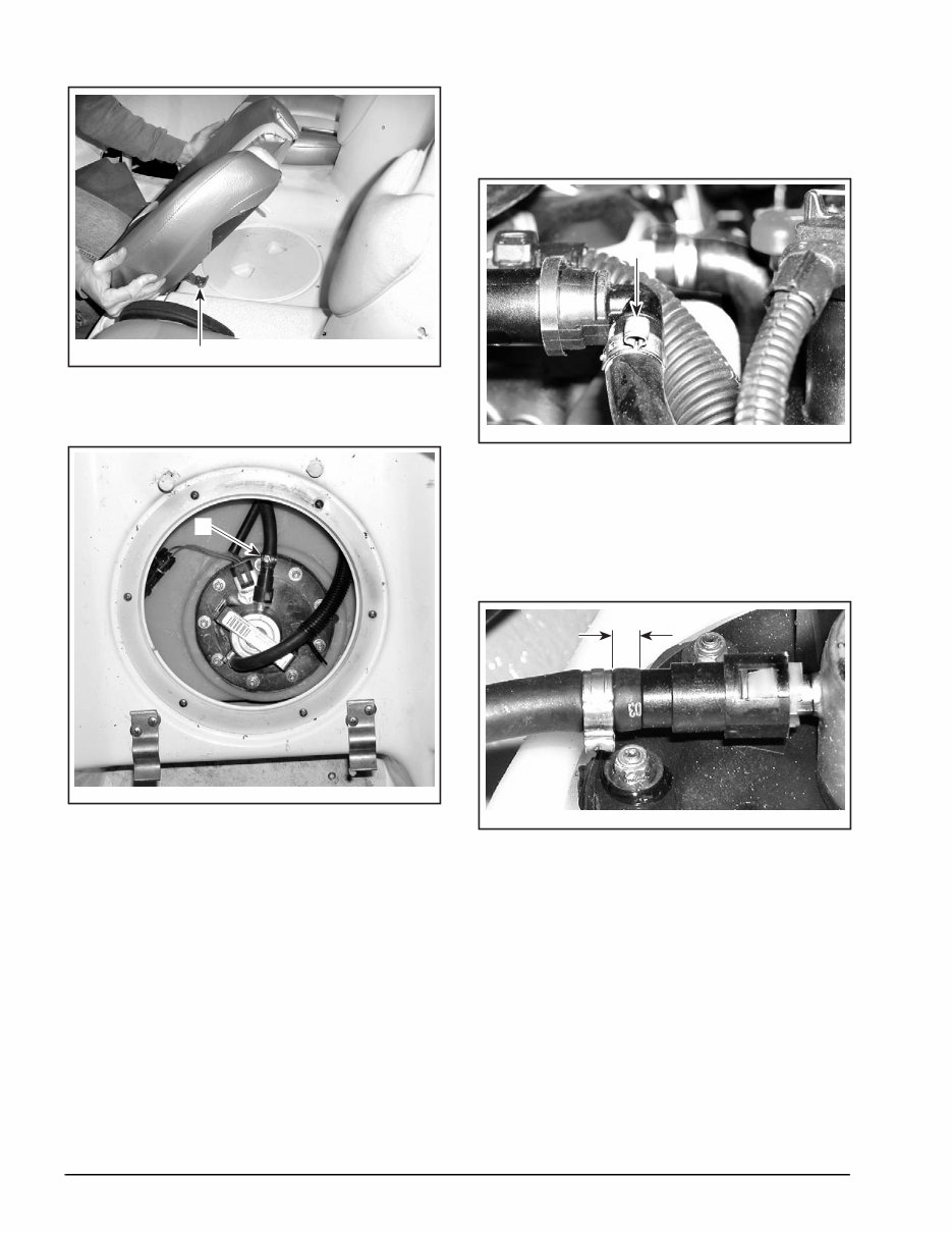
Page 2 of 9 2004-2 1. S-clip Remove access cover and inspect clamp at fuel pump module. TYPICAL 1. Inspect this clamp Remove dipstick and fuel rail cover from engine. Reinstall dipstick. From inside engine compartment, inspect clamp on fitting at fuel rail. TYPICAL 1. Inspect this clamp Fuel Line Clamp Inspection Inspect clamps on both ends of fuel supply line. Each clamp must be positioned 3 - 7 mm (0.12 - 0.28 in) from the end of the hose. Clamps either too close or too far from the ends must be replaced. TYPICAL A. 3 - 7 mm (0.12 - 0.28 in)
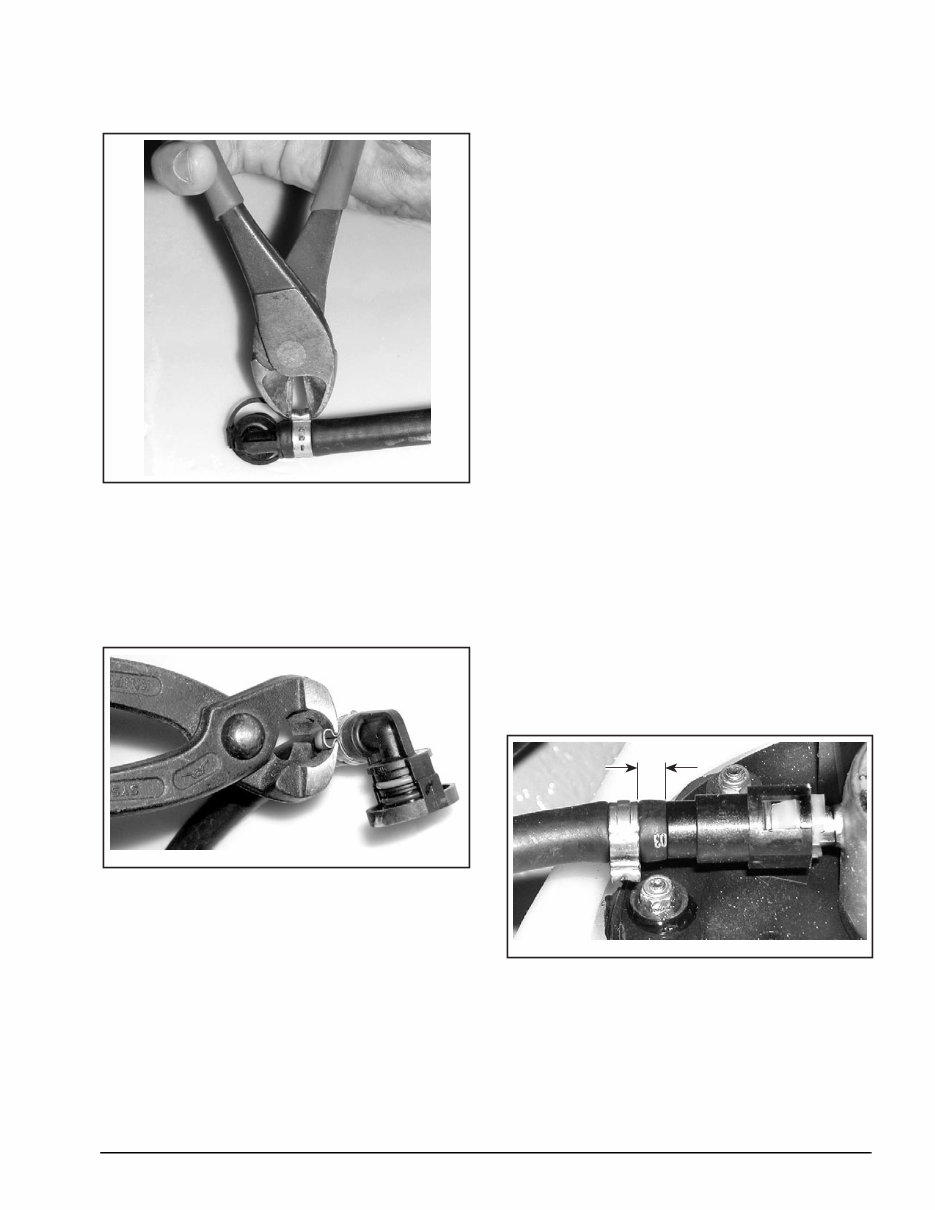
2004-2 Page 3 of 9 Clamp Replacement Release clamp(s) using cutters. TYPICAL — USE CUTTERS AS SHOWN NOTE: Before attempting to remove hose from nipple, remove fitting from fuel rail or fuel pump module to prevent damage to nipple or fitting. Remove fitting from hose and slide on new clamp(s). Reinstall fitting into hose and position and tighten clamp(s) as described above. TYPICAL — INSTALL CLAMP NOTE: Oetiker pliers (P/N 295 000 070) must be used for proper installation. Reattach fitting to fuel rail or fuel pump (whichever was removed). Turn battery switch to ON position. Install lanyard to allow fuel pump to pressurize fuel line. Check for leaks around hose ends and fit- tings. Remove and install lanyard several times while looking for leaks. Repair all leaks and re-test as necessary. Install access cover. Add new darts (P/N 293 730 021) to seat cushion and slide cushion rearward onto S-clips. Push rear sides of cushion down to engage darts in holes. Remove dipstick and reinstall fuel rail cover. Reinstall dipstick. Reinstall engine compartment storage tray and close engine cover to complete procedure. Speedster 200 Open engine compartment cover and remove en- gine compartment storage tray. Remove dipstick and fuel rail cover from each engine. Reinstall dipsticks. Turn battery switch to OFF position. Unsnap, lift and remove rear seat cushions. Remove two screws from each rear storage tub and remove both tubs. Fuel Line Clamp Inspection From rear storage tub openings, inspect clamps on both ends of fuel supply line for each engine. All clamps must be positioned 3 - 7 mm (0.12 - 0.28 in) from the end of hose. Clamps either too close or too far from the ends must be replaced. TYPICAL A. 3 - 7 mm (0.12 - 0.28 in)
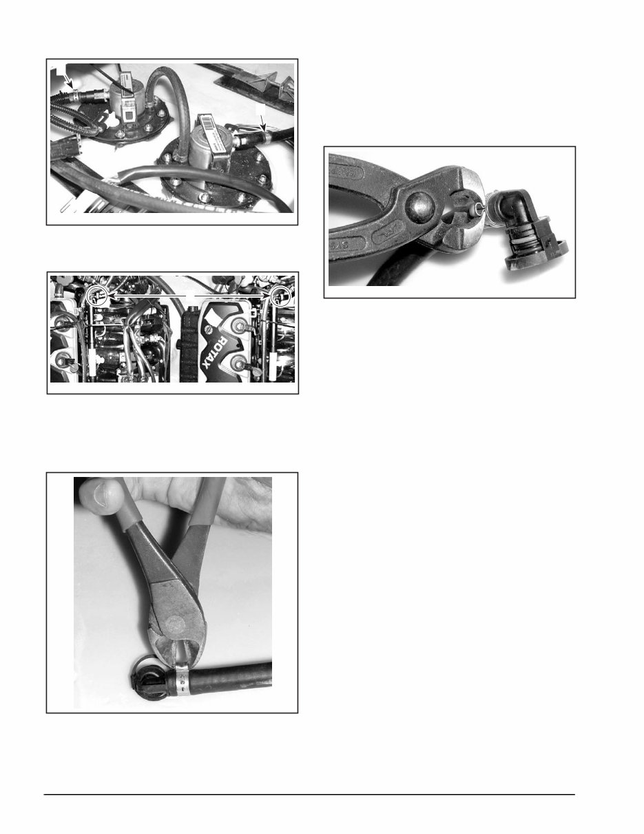
Page 4 of 9 2004-2 TYPICAL — SPEEDSTER 200 1. Inspect this clamp at port engine fuel pump 2. Inspect this clamp at starboard engine fuel pump TYPICAL — SPEEDSTER 200 1. Inspect these clamps on fuel rail fuel hose assembly at each engine Clamp Replacement Release clamp(s) using cutter. TYPICAL — USE CUTTERS AS SHOWN NOTE: Before attempting to remove hose from nipple, remove fitting from fuel rail or fuel pump module to prevent damage to nipple or fitting. Remove fitting from hose and slide on new clamp(s). Reinstall fitting into hose and position and tighten clamp(s) as described above. TYPICAL — INSTALL CLAMP NOTE: Oetiker pliers (P/N 295 000 070) must be used for proper installation. Reattach fitting to fuel rail(s) or fuel pump(s). Turn battery switch to ON position. Install lanyard to allow fuel pumps to pressurize fuel lines. Check for leaks around hose ends and fittings. Remove and install lanyard several times while looking for leaks. Repair all leaks and re-test as necessary. Reinstall storage tubs with retaining screws and slide cushions into position and snap in place. Remove dipsticks and reinstall fuel rail covers. Reinstall dipsticks. Reinstall engine compartment storage tray and close engine cover to complete procedure.
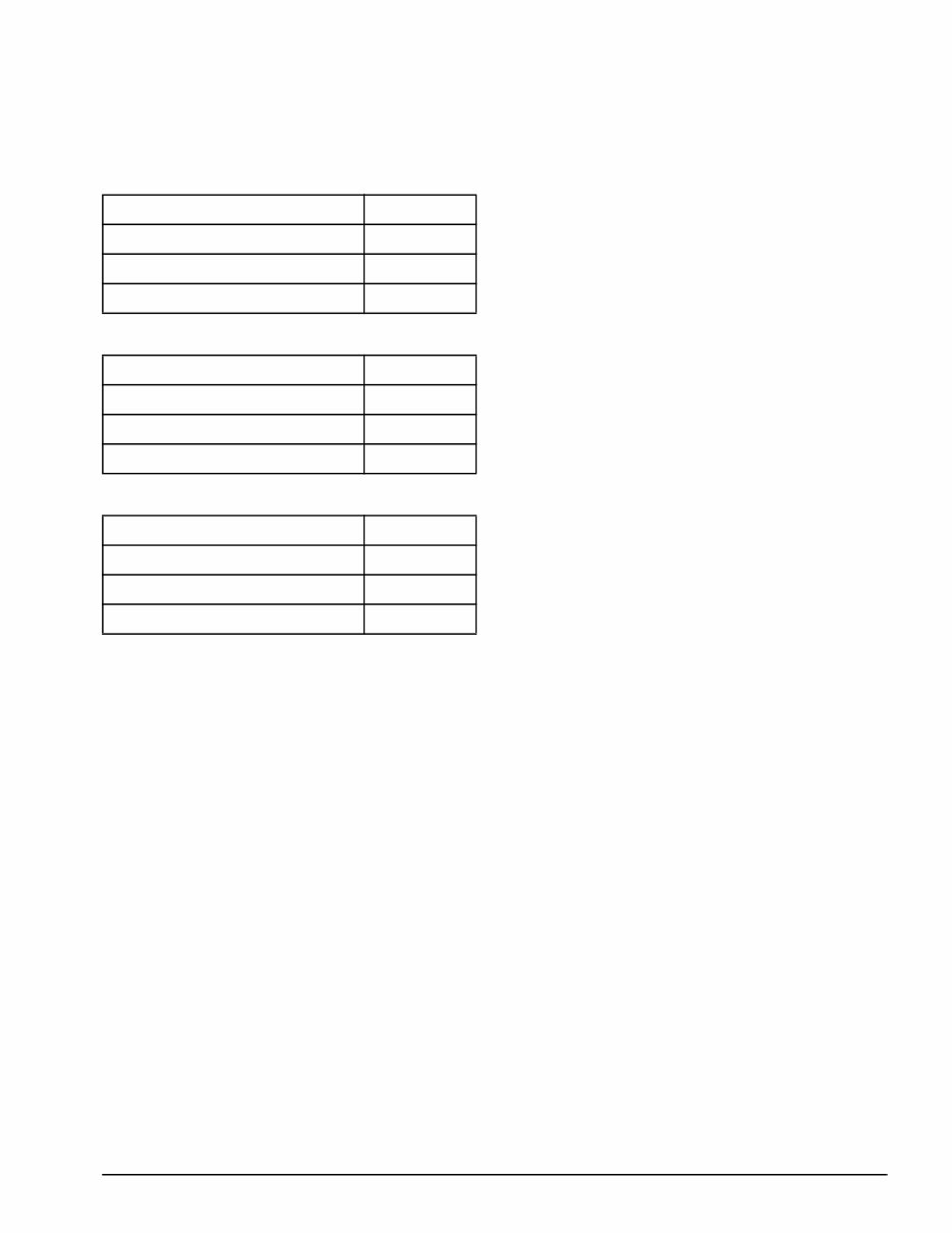
2004-2 Page 5 of 9 WARRANTY Submit a warranty claim using the following infor- mation: For 2003 Sportster 4-TEC For 2004 Sportster 4-TEC For 2004 Speedster 200 NOTE: Reimbursement for two darts (P/N 293 730 021) is included in labor time for all Sportster 4-TEC inspections. NOTE: For replacement of clamps, both Inspect and Repair boxes must be checked on the claim. Flat rate times will be added together. For claiming procedure, refer to the Dealer War- ranty Guide. NOTE: No part return is required for this campaign. Campaign Number 2003-0005 Claim Type 07 Flat Rate Time – Inspection 0.3 Flat Rate Time – Replacement 0.1 Campaign Number 2004-0003 Claim Type 07 Flat Rate Time – Inspection 0.3 Flat Rate Time – Replacement 0.1 Campaign Number 2004-0003 Claim Type 07 Flat Rate Time – Inspection 0.3 Flat Rate Time – Replacement 0.2
Upon purchasing this manual, you will receive a .PDF file containing an email contact. After contacting us, you will receive a reply with a link to access the manual for your 2004 BOMBARDIER SEA-DOO SPORTSER 4-TEC.
This comprehensive manual covers every aspect of your machine, providing detailed instructions for tasks ranging from simple maintenance, such as an oil change, to more complex procedures like a transmission swap. With hundreds of pages, it includes numerous illustrations to assist you and easy-to-understand text throughout.
The manual features a convenient search function, allowing you to quickly find the information you need, and you can easily print out specific pages as required. It serves as a Factory Service Repair Manual, offering step-by-step guidance on maintenance and repair fundamentals, empowering both professional mechanics and DIY enthusiasts with the knowledge required to effectively maintain and repair their machine.
Our commitment extends beyond providing a high-quality service manual; we also ensure excellent customer service, guaranteeing your satisfaction with your purchase.
Recently Viewed
5,521,897Happy Clients
2,594,462eManuals
1,120,453Trusted Sellers
15Years in Business
Price:
Actual Price:
2004 BOMBARDIER SEA-DOO SPORTSER 4-TEC Factory Service & Work Shop Manual