Perform an antifreeze density test. For the coolant replacement procedure, refer to the appropriate SHOP MANUAL. CAUTION: Improper antifreeze mixture might allow freezing of the liquid in the cooling system if vehicle is stored in area where freezing point is reached. This would seriously damage the engine. Failure to replace the antifreeze for storage may allow its degradation that could result in poor cooling when engine will be used. ENGINE LUBRICATION Fogging of the engine is recommended at the end of the season and before any extended storage period to provide additional corrosion protection. The goal is to lubricate the engine intake valves, the cylinders and the exhaust valves. To fog the engine , proceed as follows: Remove the two bolts that hold the fuel rail on. Remove the rail along with the three fuel injectors. Spray liberally BOMBARDIER LUBE lubricant into the intake ports. Ensure enough BOMBARDIER LUBE is sprayed in the intake ports so when the engine is cranked the exhaust valves will be fully lubricated. Crank engine several times while keeping throttle fully depressed (drown engine mode) to distribute lubricant in cylinders, on intake valves and exhaust valves. Carefully inspect O-rings condition before reinstalling fuel injectors. Replace O-rings with new ones if damaged. Lubricate O-rings with injection oil prior to installing. Reinstall the injectors. Apply Loctite † 243 (P/N 293 800 060) and torque the two bolts that hold the fuel rail on to 10 N•m (89 lbf•in). Make sure there is no leak at injectors when cranking the engine in the upcoming steps. WARNING If a leak is present, immediately stop the engine. Do not start engine until the leak is repaired. WARNING At preseason preparation, ensure to perform a fuel pressure test and ensure there is no leak. Also run engine and check for leaks. Refer to ENGINE MANAGEMENT section in SHOP MANUAL. THROTTLE BODY LUBRICATION Vehicles Without Throttle Body Quick Lubrication Kit Lubricate the throttle body to prevent corrosion on external and internal parts especially if the craft is used in salt water. Remove the air intake hose from throttle body. Open the throttle body valve by pressing slightly the throttle lever and spray BOMBARDIER LUBE lubricant (P/N 293 600 016) through the throttle body bore to lubricate valve mechanism. Spray generously the external parts of throttle body. Install air intake hose. NOTE: A throttle body optional quick lubrication kit can be purchased (P/N 295 501 048) to facilitate maintenance by creating a direct access to the throttle body valve mechanism. Vehicles With Throttle Body Quick Lubrication Kit Late production vehicles are equipped with a throttle body quick lubrication kit. Their location may be different depending on the model, but they all can be easily located with the seat removed. † Loctite is a registered trademark of Loctite Corporation. 2/ 4 2006-15 Service
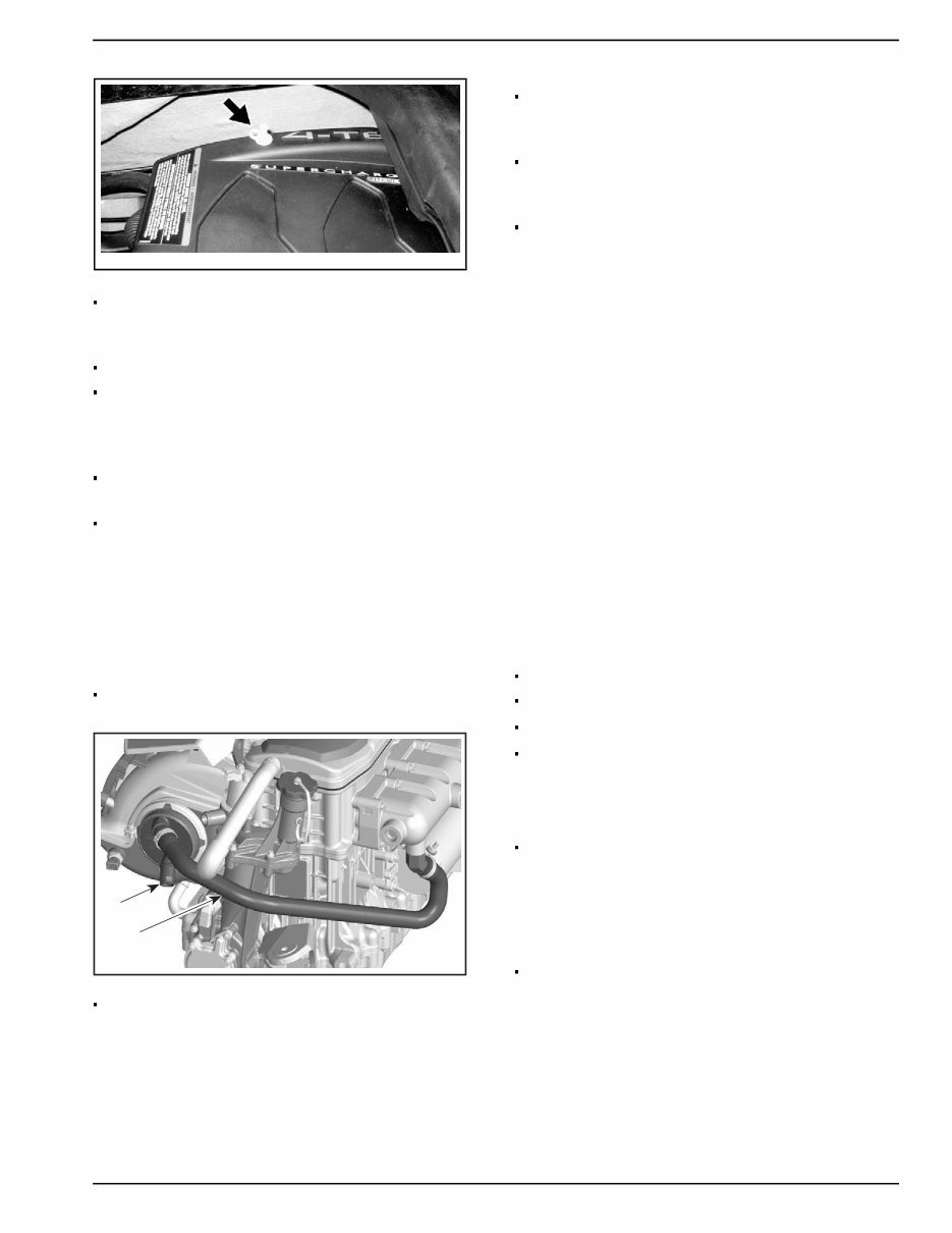
ssi2006-013-011_a Lubricate the throttle body to prevent corrosion on external and internal parts especially if the craft is used in salt water. Remove the throttle body lubrication fitting cap. Open the throttle body valve by pressing slightly the throttle lever and spray BOMBARDIER LUBE lubricant (P/N 293 600 016) through the fitting to lubricate valve mechanism. Spray generously the external parts of throttle body. Close the throttle body lubrication fitting cap. INTERCOOLER AND EXHAUST MANIFOLD ANTIFREEZE PROTECTION The intercooler and manifold are not self draining; they need the following protection. With the vehicle leveled, remove both intercooler hoses [1] and [ 2] . Let the intercooler drain and at the same time position the bottom hose as low as possible into the bilge to drain as much water from the exhaust manifold, then reconnect the bottom hose. Connect an extra piece of hose to the upper intercooler nipple and pour approximately 200 mL (6.76 oz U.S.) of antifreeze into the intercooler. Then pour approximately 300 mL (10.14 oz U.S.) of antifreeze into the upper Intercooler hose, toward the exhaust manifold. Reconnect the intercooler upper hose. CAUTION: Failure to pour antifreeze into the intercooler and exhaust manifold, may cause severe damage to these components. CAUTION: Use only undiluted antifreeze (100% concentration). The premixed antifreeze available from BRP is NOT suitable for this particular application. Its concentration will be reduced when mixed with remaining water trapped in water jackets. NOTE: Antifreeze must be compatible with internal combustion aluminum engines. It is recommended to use biodegradable antifreeze. This will contribute to protect the environment. Recreational vehicle (RV) antifreeze can be used. NOTE: The engine will not have to run during this operation but should have been ran before, to exhaust as much water as possible, from cooling system components. BATTERY Remove Clean Charge Store Refer to CHARGING SYSTEM in SHOP MANUAL. WATERCRAFT CLEANING Clean the bilge with hot water and mild detergent or with bilge cleaner. Rinse thoroughly. Lift front end of watercraft to completely drain bilge. If any repairs are needed to body or to the hull, touch up paint and Gelcote †† repair kits are available. Replace damaged labels/decals. Wash the body with soap and water solution (use mild detergent only). Rinse thoroughly with fresh water. Remove marine organisms from the hull. Apply a nonabrasive wax. †† Gelcote is a registered trademark of Gelcote International. Service 2006-15 3/ 4
CAUTION: Never clean fiberglass and plastic parts with strong detergent, degreasing agent, paint thinner, acetone, etc. If the watercraft is to be stored outside, cover it with an opaque tarpaulin to prevent sun rays and grime from affecting the plastic components, watercraft finish as well as preventing dust accumulation. CAUTION: The watercraft must never be Ieft in water for storage. Never leave the watercraft stored in direct sunlight. ANTICORROSION TREATMENT Wipe off any residual water in the engine compartment. Spray BOMBARDIER LUBE lubricant over all metallic components in engine compartment. Lubricate the throttle cable with BOMBARDIER LUBE lubricant. Apply an anticorrosion product (P/N 219 700 304) on drive shaft. Refer to PROPULSION is appropriate SHOP MANUAL. NOTE: The seat should be partially left opened during storage. This will avoid engine compartment condensation and possible corrosion. CHECK LIST OPERATION ✔ Propulsion System Fuel System Engine Oil and Filter Change Exhaust Cooling System Flushing Close Loop Cooling System (engine) Engine Lubrication Throttle Body Lubrication Intercooler and Exhaust Manifold Antifreeze Protection Battery Watercraft Cleaning Anticorrosion Treatment 4/ 4 2006-15 Service
SPORTSTER 4-TEC – 03/2003 219 301 590 A1 PARTS CATALOG CATALOGUE DE PIÈCES 2003 2003 2003 2003 2003 SPORTSTER 4-TEC JCP-0301 (DB) WARNING For user safety, marine Rotax engines designed for Sea-Doo Sport Boats must not be used to power products other than Sea-Doo Sport Boats. AVERTISSEMENT Pour la sécurité des utilisateurs, les moteurs nautiques Rotax conçus pour les bateaux sport Sea-Doo ne doivent pas être utilisés pour des fins autres que de faire fonctionner les bateaux Sport Sea-Doo. Bombardier Inc. et ses filiales se dégagent de toute responsabilité pouvant découler des utilisations autres que celle prescrite. Les concessionnaires qui ne se conforment pas à cet avis peuvent être tenus responsables financièrement advenant des blessures. Bombardier Inc. se réserve le droit d’effectuer des changements dans le dessin et les caractéristiques de ses véhicules et/ou d’y effectuer des apports ou des améliorations, cela sans s’engager d’aucune façon à effectuer lesdites opérations sur les véhicules déjà fabriqués. Bombardier Inc. and its subsidiaries denies any responsibility for any usage other than the one prescribed. Dealers that do not follow this practice may be financially liable should injury occur. Bombardier Inc. reserves the right at any time to discontinue or change specifications, designs, features, models or equipment without incurring obligation.
SPORTSTER 4-TEC – 03/2003 219 301 590 A2 PARTS CATALOG / CATALOGUE DE PIÈCES The illustrations figuring in this parts catalog show typical construction of the different assemblies and, in all cases, may not reproduce the full detail or exact shape of the parts shown. However, they represent parts which have the same or similar function. Les illustrations contenues dans ce catalogue indiquent la disposition des pièces les unes par rapport aux autres. Il est donc possible qu’elles ne rendent pas compte de la forme exacte de ces pièces ainsi que de leurs détails de fabrication. Ces illustrations ont pour but d’identifier des pièces qui remplissent la même fonction ou une fonction identique. SYMBOLS USED IN THIS CATALOG @ In «Quantity» column means «Use as Required». Opt In «Quantity» column means «Optional». N In «Numerical» column means «New Parts». — XXX — Parts marked with «XXX» are not available as spare parts. - A bold description indicates that several parts are included in this item. SYMBOLES UTILISÉS DANS CE CATALOGUE @ Dans la colonne «Quantité» signifie «Au besoin». Opt Dans la colonne «Quantité» signifie «En option». N Dans la colonne «Numérique» signifie «Nouvelle pièce». — XXX — Les articles marqués d’un «XXX» ne sont pas disponibles comme pièces de remplacement. - Une description en caractère gras signifie qu’il y a plus d’une pièce dans cet item. 2003 Sport Boats Model/ Modèle bateaux sport Vehicle Codification/ Code du véhicule Rotax Engine Type/ Type de moteur Rotax SPORTSTER 4-TEC WITH TOWER/ SPORTSTER 4-TEC AVEC TOUR 5768 «1503» SPORTSTER 4-TEC 5770 «1503»
SPORTSTER 4-TEC – 03/2003 219 301 590 A3 TABLE OF CONTENTS TABLE DES MATIÈRES ENGINE MOTEUR Engine Block ............................................................ Bloc moteur ............................................................ A4, A5 A4, A5 A4, A5 A4, A5 A4, A5 Crankshaft, Piston and Balance Shaft ...................... Vilebrequin, piston et arbre de balancement ............ A6 A6 A6 A6 A6 Cylinder Head .......................................................... Tête de cylindre ....................................................... A7, A8 A7, A8 A7, A8 A7, A8 A7, A8 PTO Cover and Magneto .......................................... Couvercle PDM et magnéto .................................... A9, A10 A9, A10 A9, A10 A9, A10 A9, A10 Oil Separator ............................................................ Séparateur d’huile .................................................... A11 A11 A11 A11 A11 Air Intake Manifold ................................................... Collecteur d’admission d’air .................................... A12 A12 A12 A12 A12 Engine Wiring Harness ............................................. Câblage de fils du moteur ........................................ B1 B1 B1 B1 B1 Engine Support and Air Intake .................................. Support moteur et admission d’air ........................... B2 B2 B2 B2 B2 Exhaust System ...................................................... Système échappement ........................................... B3 B3 B3 B3 B3 ELECTRICAL SYSTEM SYSTÈME ÉLECTRIQUE Electrical System ..................................................... Système électrique ................................................. B4 B4 B4 B4 B4 Electrical Accessories - 1 ........................................ Accessoires électriques - 1 ..................................... B5, B6 B5, B6 B5, B6 B5, B6 B5, B6 Electrical Accessories - 2 ........................................ Accessoires électriques - 2 ..................................... B7, B8 B7, B8 B7, B8 B7, B8 B7, B8 Engine Harness ........................................................ Câblage de moteur .................................................. B9, B10 B9, B10 B9, B10 B9, B10 B9, B10 COOLING SYSTEM SYSTÈME DE REFROIDISSEMENT Cooling System ....................................................... Système de refroidissement ................................... B11 B11 B11 B11 B11 FUEL SYSTEM SYSTÈME D’ALIMENTATION Fuel System ............................................................. Système d'alimentation .......................................... B12, C1 B12, C1 B12, C1 B12, C1 B12, C1 PROPULSION AND DRIVE SYSTEMS SYSTÈME D’ENTRAÎNEMENT ET DE PROPULSION Propulsion System ................................................... Système de propulsion ............................................ C2, C3 C2, C3 C2, C3 C2, C3 C2, C3 Pump ystem ............................................................ Système de pompe ................................................ C4 C4 C4 C4 C4 Reverse ................................................................... Marche arrière ......................................................... C5 C5 C5 C5 C5 Control Handle ......................................................... Manettes de contrôle .............................................. C6, C7 C6, C7 C6, C7 C6, C7 C6, C7 STEERING SYSTEM SYSTÈME DE DIRECTION Steering System ...................................................... Système de direction .............................................. C8 C8 C8 C8 C8 HULL AND BODY COQUE ET PONT Hull - 1 ..................................................................... Coque - 1 ................................................................ C9 C9 C9 C9 C9 Hull - 2 ..................................................................... Coque - 2 ................................................................ C10 C10 C10 C10 C10 Lower Hull ................................................................ Coque inférieure ...................................................... C11 C11 C11 C11 C11 Rear Ladder ............................................................. Échelle arrière ......................................................... C12 C12 C12 C12 C12 Engine Compartment ............................................... Compartiment moteur ............................................. D1 D1 D1 D1 D1 Central Cover and Accessories ................................ Couvercle central et accessoires ............................. D2 D2 D2 D2 D2 Body and Accessories ............................................. Carrosserie et accessoires ...................................... D3, D4 D3, D4 D3, D4 D3, D4 D3, D4 Tower and Bimini Top ............................................... Tour et toit bimini ..................................................... D5 D5 D5 D5 D5 Front Storage Compartment ..................................... Compartiment à bagages avant .............................. D6 D6 D6 D6 D6 Seats ....................................................................... Sièges ..................................................................... D7 D7 D7 D7 D7 Decals ..................................................................... Décalques ............................................................... D8 D8 D8 D8 D8 DOCUMENTATIONS DOCUMENTATIONS Numerical Index ....................................................... Index numérique ..................................................... D9 D9 D9 D9 D9 D10 D10 D10 D10 D10 New Parts ................................................................ Nouvelles pièces ..................................................... D10 D10 D10 D10 D10
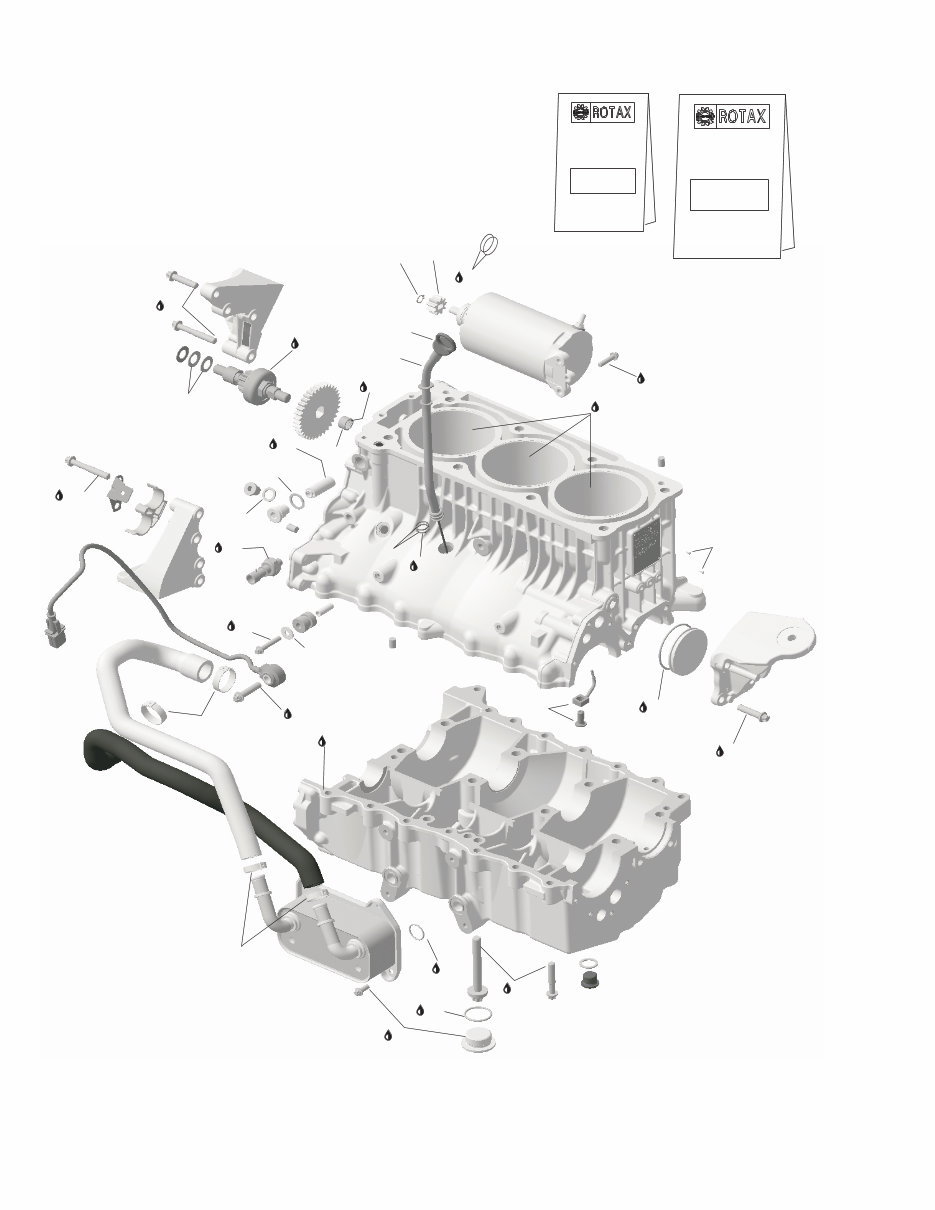
SPORTSTER 4-TEC – 03/2003 219 301 590 A4 SPORTSTER 4-TEC (5770) SPORTSTER 4-TEC (5768) ENGINE/ MOTEUR ENGINE BLOCK/ BLOC MOTEUR N 1 N 1 N 1 N 1 N 1 è 8 420 888 812 Engine Block Ass’y Engine Block Ass’y Engine Block Ass’y Engine Block Ass’y Engine Block Ass’y ................................ ................................ ................................ ................................ ................................ Bloc moteur ass. Bloc moteur ass. Bloc moteur ass. Bloc moteur ass. Bloc moteur ass. ................................... ................................... ................................... ................................... ................................... 1 1 2 420 632 010 Pin M8 x 12 .............................................. Goupille M8 x 12 ..................................... 6 6 N 3 N 3 N 3 N 3 N 3 420 956 775 Oil Hole Adaptor ...................................... Obturateur d’ouverture d’huile ............... 3 3 N 4 N 4 N 4 N 4 N 4 420 430 623 Gasket Ring ............................................. Anneau étanche ..................................... 1 1 N 5 N 5 N 5 N 5 N 5 420 240 233 Plug Screw M16 ..................................... Vis d’obturation M16 .............................. 1 1 6 420 250 015 Sealing Ring ............................................ Anneau étanche ..................................... 1 1 N 7 N 7 N 7 N 7 N 7 420 841 923 Plug Screw M12 ..................................... Vis d’obturation M12 .............................. 1 1 N 8 N 8 N 8 N 8 N 8 420 641 120 Torx Screw M10 X 82 ............................. Vis hexalobulaire M10 x 82 ................... 8 8 N 9 N 9 N 9 N 9 N 9 420 641 203 Torx Flanged Screw M8 x 45 ...................... Vis hexalobulaire à épaulement M8 x 45 ..... 15 15 N 10 N 10 N 10 N 10 N 10 è 11 11 11 11 11 420 641 170 Plug Screw M30 x 1.5 Plug Screw M30 x 1.5 Plug Screw M30 x 1.5 Plug Screw M30 x 1.5 Plug Screw M30 x 1.5 .......................... .......................... .......................... .......................... .......................... Vis d’obturation M30 x 1.5 Vis d’obturation M30 x 1.5 Vis d’obturation M30 x 1.5 Vis d’obturation M30 x 1.5 Vis d’obturation M30 x 1.5 ................. ................. ................. ................. ................. 8 8 N 11 N 11 N 11 N 11 N 11 420 631 300 O-Ring ...................................................... Joint torique ............................................ 8 8 N 12 N 12 N 12 N 12 N 12 420 249 073 Grooved Pin ............................................. Goupille cannellée .................................. 2 2 N 13 N 13 N 13 N 13 N 13 420 430 405 O-Ring ...................................................... Joint torique ............................................ 1 1 N 14 N 14 N 14 N 14 N 14 420 660 110 Plug Cover ............................................... Couvercle d’obturation ........................... 1 1 N 15 N 15 N 15 N 15 N 15 420 811 790 Front Engine Bracket .............................. Support moteur avant ............................ 1 1 N 16 N 16 N 16 N 16 N 16 420 641 188 Torx Flanged Screw M8 x 35 ...................... Vis hexalobulaire à épaulement M8 x 35 ..... 4 4 N 17 N 17 N 17 N 17 N 17 420 811 785 Engine Bracket PTO (Exhaust) ................ Support moteur PDM échappement ..... 1 1 N 18 N 18 N 18 N 18 N 18 420 641 188 Torx Flanged Screw M8 x 35 ...................... Vis hexalobulaire à épaulement M8 x 35 ..... 2 2 N 19 N 19 N 19 N 19 N 19 420 641 213 Torx Flanged Screw M8 x 55 ...................... Vis hexalobulaire à épaulement M8 x 55 ..... 2 2 N 20 N 20 N 20 N 20 N 20 420 811 780 Engine Bracket PTO (Intake) ................... Support moteur PDM admission ............ 1 1 N 21 N 21 N 21 N 21 N 21 420 851 740 Retaining Plate ....................................... Plaque de retenue .................................. 1 1 N 22 N 22 N 22 N 22 N 22 420 641 213 Torx Flanged Screw M8 x 55 ...................... Vis hexalobulaire à épaulement M8 x 55 ..... 4 4 N 23 N 23 N 23 N 23 N 23 420 660 290 Hose Bracket ........................................... Support de boyau ................................... 1 1 N 24 N 24 N 24 N 24 N 24 420 236 252 Chain Tensioner ...................................... Tendeur de chaîne .................................. 1 1 N 25 N 25 N 25 N 25 N 25 420 430 623 Gasket Ring ............................................. Anneau étanche ..................................... 1 1 N 26 N 26 N 26 N 26 N 26 420 640 453 Plug Screw M16 ..................................... Vis d’obturation M16 .............................. 1 1 N 27 N 27 N 27 N 27 N 27 420 847 970 Spacer ..................................................... Entretoise ................................................ 2 2 N 28 N 28 N 28 N 28 N 28 420 660 090 Rubber Bracket ....................................... Support de caoutchouc .......................... 2 2 N 29 N 29 N 29 N 29 N 29 420 827 968 Flat Washer 6.4 mm ................................ Rondelle plate 6.4 mm ........................... 2 2 30 30 30 30 30 420 641 258 Torx Flanged Screw M6 x 35 ................. Vis hexalobulaire à épaulement M6 x 35 . 2 2 N 31 N 31 N 31 N 31 N 31 420 256 777 Oil Pressure Switch ................................. Interrupteur de pression d’huile ............ 1 1 N 32 N 32 N 32 N 32 N 32 420 664 030 Knock Sensor .......................................... Capteur de détonation ........................... 1 1 N 33 N 33 N 33 N 33 N 33 420 641 188 Torx Flanged Screw M8 x 35 ...................... Vis hexalobulaire à épaulement M8 x 35 ..... 1 1 N 34 N 34 N 34 N 34 N 34 420 888 850 Oil Radiator .............................................. Radiateur d’huile .................................... 1 1 N 35 N 35 N 35 N 35 N 35 420 250 055 O-Ring ...................................................... Joint torique ............................................ 2 2 N 36 N 36 N 36 N 36 N 36 420 641 048 Torx Flanged Screw M6 x 16 ................. Vis hexalobulaire à épaulement M6 x 16 . 4 4 N 37 N 37 N 37 N 37 N 37 420 922 796 Formed Hose ........................................... Boyau formé ............................................ 1 1 N 38 N 38 N 38 N 38 N 38 420 922 791 Formed Hose ........................................... Boyau formé ............................................ 1 1 N 39 N 39 N 39 N 39 N 39 420 851 663 Gear Clamp .............................................. Bride de serrage ..................................... 2 2 N 40 N 40 N 40 N 40 N 40 420 851 673 Gear Clamp .............................................. Bride de serrage ..................................... 2 2
Upon purchasing this manual, you will receive a .PDF file containing an email address for further assistance. After contacting the provided email, you will receive a reply with a link to access the manual for your 2001 Sea Doo PWC Personal watercraft.
This comprehensive manual covers every aspect of your machine, providing detailed guidance on every nut and bolt. With its extensive content spanning hundreds of pages, it equips you to address a wide range of issues, from routine maintenance tasks like oil changes to more complex procedures such as transmission swaps. The manual includes numerous illustrations to assist you in your work, accompanied by easily understandable text.
Utilize the search function to navigate the manual efficiently and print the necessary pages as needed. This Factory Service Repair Manual serves as a thorough guide, walking you through the essential principles of maintenance and repair in a step-by-step manner, imparting the expertise that factory-trained technicians possess. By leveraging the insights within this service repair manual, any owner can confidently make informed decisions regarding the upkeep and repair of their machine.
Our commitment extends beyond providing a high-quality service manual; we also offer exceptional customer service, ensuring your satisfaction is guaranteed.
Recently Viewed
5,521,897Happy Clients
2,594,462eManuals
1,120,453Trusted Sellers
15Years in Business
Price:
Actual Price:
2001 Sea Doo PWC Personals Factory Service & Work Shop Manual