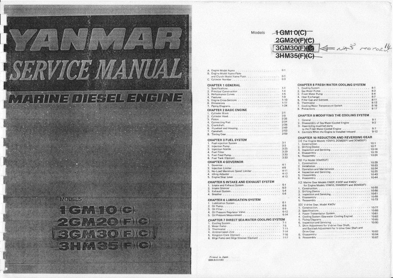
Models A- Engine N4odel Name B. Engine Model Name Plate and Clutch Model Name Plate. C. Cylinder Number CHAPTER 1 GENERAL 1- Sp6itications 2. Principal Construction . 3. Performance Cures. . . . 4. F€tur6 5. Engine Cr6-S€1ions 6. Oimensions 7. Piping Diagrams. CHAPTER 2 BASIC ENGINE 1. CylinderBl@k ......... 2. Cylinder H@d . 3. Piston. . 4. ConnstingRod. ..... ... 5. Cranksha{t. 6. Flywh€l and Housing . . . . 7. Camshaft. 8. Timiog G€r . CHAPTER 3 FUEL SYSTEM '1. Fuel ini*lion Systm . . . . 2. Inietion Pump 3. Ini€lion Nozzle. 4. Fuel Filter 5. Fuel F@d Pump. 6- FuelTank (Oprion). . CHAPTER 4 GOVERNOR 1. Gowrnor. 2. Inietion Limiter.. 3- No-Load Maximum Speed Limiter 4. ldling Adjuster 5. Engine Stop Lffr . . . CHAPTER 5 INTAKE AND EXHAUST SYSTEM 1. Inbke and Exhaust Sys€m CHAPTER 8 FRESH WATER COOLING SYSTEM 1. Coolingsystem ... . 8-1 2. SeiwaterPump. ..-.- ..... 83 3. Fr6hwaterPump .... , .... 8{ 4. H€tExchaoger . ... - ...... 8-7 5.Filtercapandsubtank.... ... 8-1'l 6'Them*tat ""' 8-13 ?. CoolingwaterTemperatu.eswitch. ...... 8-16 g'Pr*autions ""' 8-17 CHAPTER 9 MODIFYING THE COOLING SYSTEM 1. General ?. Disasmbly ol S@ Water-C@led e"gi"" . . . . 3. A$embling modified pars to the Fr6h Water-Cooled Engine 4. CautioN whs the Engire is Install€d Inb@rd . ^/4-S' n- --n!p 9-1 9-2 9-7 9-12 o-1 0-1 0-3 '| "1 14 1-5 1-9 1-10 1-17 t-24 . 2-1 . 2-9 . 2-24 . 2-U . 234 . 249 . 2-53 5-1 5-3 s4 56 6-r 6-5 6,9 6-12 6-14 CHAPTER IO REDUCTION AND REVERSING GEAR lAl For Engine Models 1GMl0,2GM2O(F) and 3GM3O(FI l.Co6truction. ..... 10-1 3-29 4-9 4-11 4-12 4-13 2. Shifiing Dwice 3- Insprction and S€ryicing. 4. Disasmblv 5. P€smbly Drive Gear . 8- Disasembly 9. R€ssmbly .10-7 . 10-14 10-24 . lo-50 . 1056 . 10€1 . 1068 .10-73 lBl ForModel3GM35(F| l.construction ""'1G29 2. lnsbll€tion .""'10-33 3- OrrationandMainrenane ... - 1034 4. l6Btionandsewicing. -. ...1G35 5. oisa$emblv """1040 6. ReawblY ""-'10.44 [Cl Marire Ger Models KM2P. KN'!3Psnd KM3V tor Engine Models lGMlO,2GM2O(F} and 3GM3O(F) 2. Intake Silencg 3. Exhaust Svstm. 4. Br€ther CHAPTER 6 LUBRICATION SYSTEM 1. Lublication System. 2. Oil Pume. 3. Oil Filrer. 4. Oil Pr6uie RegulatorValve. 5. Oil Pr6ure M€suremqi CHAPTER 7 DIRECT SEA.WATER COOLING SYSTEM 'L Coctruction. .. 2- ShiftingDwice..... 3. Insp€ction and Sedicing 4. Dis$mbly 5. Rea$emblv IDl Vdrive G€r, Model KM3V l. Construction. 2. Speifications 3. P@er Transmission System . ...-1C77 .-..10€o .... 10€1 4. Anticorr6ionzink. . . . . . . . . 5. King6tonc@k(Optionl ...... 6- Bilge Pump and Bilge Srrairer (Optionl 7-^ 7 -11 ...... 7-14 ...... 7_16 4. Coolingsystem{S€-watercoolingEnginet. . . . . . . . . 1O€2 5. Piping Diagrams. " 1O€5 6. InsFtionandsedicing.. ." 1G9O 7. Shim Adjusrmfft for Vdriw Gear Shaft, and gacklashAdiustment for Vdrive G€r Shaft and .... 1G92 .... 10-94 . .. . 10€7 1- Cooling System . 2. water Pump . 3. Therm6tat ... Pintcd in Jw 0000404136r
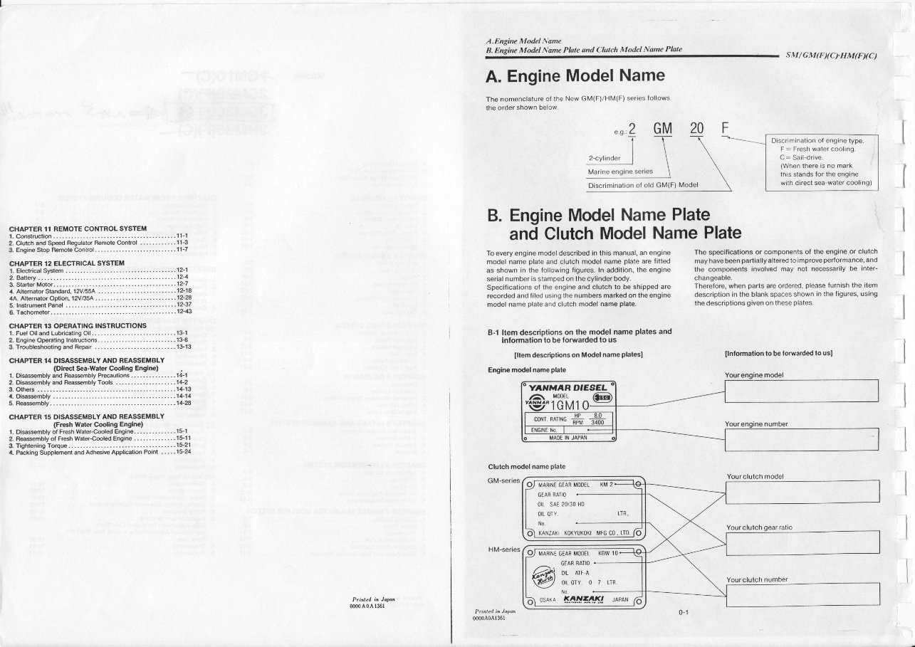
A.Engine Model Name B. Engine Model Name Phle ond Clulch Model Name Plale SM/GM(F)(C).HM(F)(C) A. EngineModel Name The nomenclatureoJ the New GM(F)/HM(F) series lollows the order shown below. ".n.'2 I 2-cylinder I Marine engine seraes GM 20 F Discriminationof old GM(F) Model B. Engine ModelNamePlate To every engine model described in this manual, an engine model name plate and clutch model name plate are litted as shown in the following figures. In addition, the engine serial number is stampedon the cylinder body. Specificationsof the engine and clutch to be shipped are recorded and liled using the numbers marked on the engine model name plate and clulch model name plale. B-1 ltem descriptions on lhe model name plales and infomation lo be lorwarded to us fllem descriptions on Model name phlest The specilications or components of the engine or clutch may have been partiallyaltered to improve performance, and the components involved may not necessarily be inter- changeable. Therefore, when parts are ordered, please furnish the ilem description in the blank spacesshown in the ligures, using the descriptionsgiven on these plates. llnlomation to b€ lorwarded to usl and ClutchModelNamePlate Clulch model name olate GM-series HM-series Ptided it Jw 0000 A0 A l36l 0000A0A136r C'{APTER 11 REMOTE CONTROL SYSTEM t. Construction .... . . .. . .. . .. . .. ... . '11-1 2. Clutch andSp€ed Regulatq Rmote Control, . . .. -.. . ... 1 1-3 3. Eogire Stop Remote Control ... .. . .. .... . .. ... .. . -. . -. . 1 1-7 CflAPTER 12 ELECTRICAL SYSTEM '1. Electdelsystem ............ -.'..12-1 2 Battery.- ........ ...... -- ........ 12-4 3 startqMotor"'" '"""'"'"'"12-7 4. AttemtorStandard, 12Vl55A ... - ........... - - ......... '12-18 4A.Altermtor Opli6, 12VB5A -. .. . ..... -. -.. -. .. . .. -.. .. 12-m 5. l6trumtPaoef ....... --- ........ 12-37 6. Tachomets ...... .. - - ............ 12-43 CfIAPTER 13 OP€RATING INSTRUCTIONS t- Fuel Oil andLubd€ting Oil ........ - ................... 13-1 2. engire Opeating Instructions ........... - .... -., ....... 13-8 3 Troubleshobting and Fepair . . . - . . . . . . ,. . . . . . , . . . . . - . . - 1&13 CIIAPTER 14 DISASSEI,IBLY ANO REASSEMALY (Dlr€ct Seawattr Cooling Engln€) '1. Disasmbly and R@mbly Pr@utions . . - .... .. ... ... 1.1-1 2. Diwmbly a.rd R€sbly T@ls ....... ..... .. . .. . -. 1+2 3. Oihe6 .. .. . . .... . -. .. - -. .. . .. ... 1+13 a. Oisasmbly -. -. .. . .. ....... ... ... 1+14 5. R€smbly. . -. . - .. . .. . -. -. ... ... 1+28 iffi,rroP MARINE GEAR MOOEL KM 2 orL sAE 20i 30 H0 OIL OTY LTR. KANZAKI KOKYUKOKI MFG CO,. LTD MAffINE GEAfl MODEL KBW 10 6d';: :::: @;ioi, ^o , ,,, osaxa l!.Ll!!f!!J uenru Yourclutch gear ratio
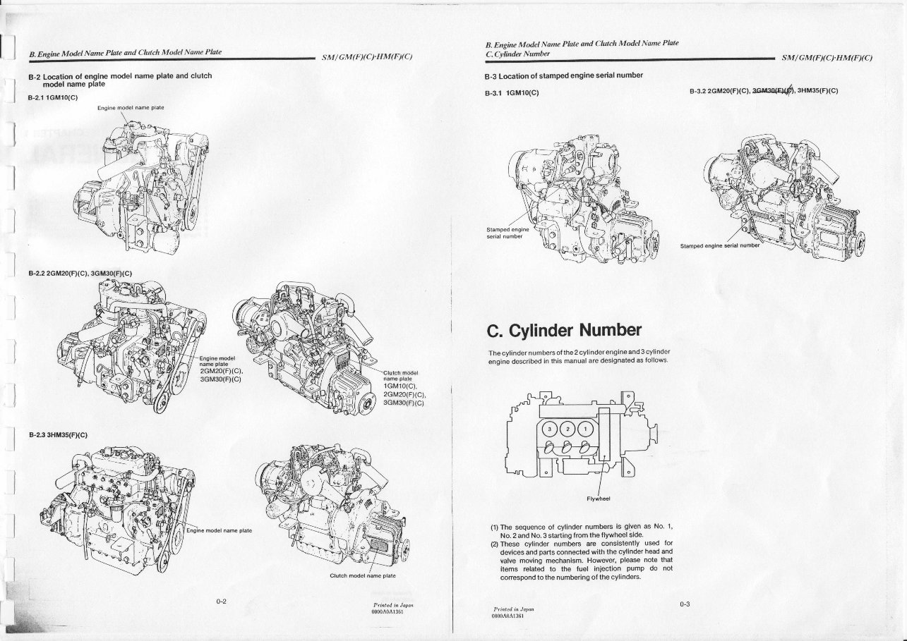
Engine model 6ame Plate B. Engine Mdel Nane Plate md Cfulch Model Nme Phle 8.2 Location ol engine model name plate and clulch model name Plate B-2"1 1GM10(C) sM/GM(F)(cIHM(F)(c) mdel model nare Plate 2GM20(F)(C), 3GM3o(F)(C) nare plate 1GM10(C), 2GM20(F)(c), 3GM30(F)(C) B-23 3HU35(FXC) 00004041361 model name plal€ B. Engine Modet Nme Phte ond Cfulch Modcl Nune Plale C.Cylinder Numbet sM/GM(F)(C).HM(F)(C) 8.3 Location ol stamped engine serial number B-3.1 1GM10(c) C. Gylinder Number The cylinder numbers oI the 2 cylinder engine and 3 cylinder engine describ€d in lhis manual are designated as follows. (1) The sequence of cylinder numbers is given as No. 1, No. 2 and No. 3 starting lrom the flywheel side. (2) These cylinder numbers are consistently used lor devices and parts connected with the cylinder head and valve moving mechanism- However, please note that items related to the luel iniection pumP d0 not conespond to the numbering ot the cylinders. 0000404r361 s-3.2 2cM2o(FX c I, aru2uqpt$ sHMss(FXc)
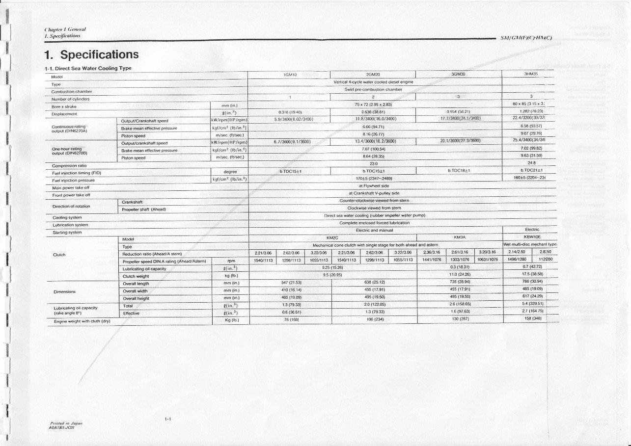
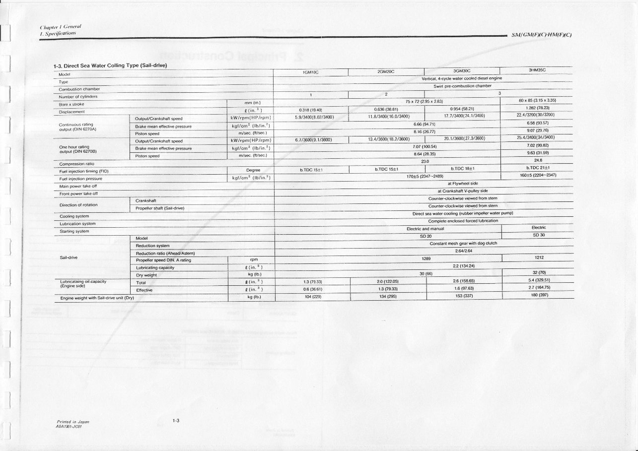
('hapter I Central l - Specifczlious 1. Specifications 1-1- Oirect Sea Water Cooling TYPe silt/G^t(F)(cltttt{c) 80 x 85 (3 15 x 3: 't.2€.2 l.74.231 22.413200(&1321 6.58 (93.57) 9.07 (29.76) 25.41W(U/U\ 7.02 (9!).82) I 63 (3r.sgl 24.8 b.Toc2lal 1@X5lU4-2! Combustid chadber Venial 4rycle water c@led diesel engire 75 x 72 (2.95 x 2.83) 0.99 (58 2r) 0.316 (19 40) 17 .1 /3&(24.1/34fnl 6.66 (94 71) 20.r /3mo(27.3/3600) kgf/cm2 (tb/in.2) broclsrllb.Toclsrllb.TDc18al M6hanical core clutch with single stage tor both ah€d aod astern Popeller sp€ed DIN.A ating (Ah€d/Astern) r1.0 (24.261 ?a5 €ar4) 455 (11r1) 4s5(r7.91) 410 (r6 14) r.6 (97.631 r3o (287) I I I t I ) I I I Numbe. of cylindeG Bore x slroke Oispl&ment Cdrian|ff6tng outplt (OlN6270Al O€ hor rafing outpd (OlN6270Bl Cofrpa6is (atro F@l iniectiq timing (FlO) F(Fl ini€lon pr6u@ Main @rer take off Frodt pwer take ofl f).redim ol ,obri6 C@ling system Lubra(5tion systs Sla.ting system cI|11sions Lubri@ling oil €pacity (rake angleS"l Engi@ reighr with cluth (dry) Printed in Japan a0At$tJc0l t, t at Flywhel side at Crankshaft V-pulley side Cdntsrl€tli* vi,ew€d tam stern Cl@kwis viered kom stc.rn Dir6l *a water c@liog (.ubber impeller water pump) Complete ercklsed forced lubri€tion E|ectric KBWl0€ multk i$ rehanl type rr2980 17.5 (3t1.58) 786 ($.94) 485 (19.0S) 617(24.29) i 2.7 116l.751 158 (348)
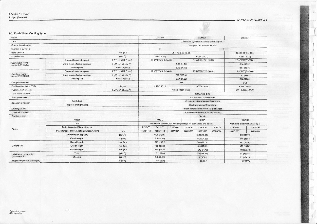
Chapler I Oeneral l. Specifiealions SIVI / G IVI( FXC T IT M ( FXC ) 1-2. Fresh Waler Coollng Typ€ Model Type Cmbustion chamber Numbs ol cytindeG Bore x sl(oke Oisplacemenl Conlin!@s .ating output (DlN 62704) Lukicaring ol €prcity (rake angle 8P) Ore h@r Gt,ng outpul (OlN 62708) Coooa6sion aatio Fuel inieclion liming (FlO) F@l iniecti$ p.6su.e Maio porer lake ofl Frmt rcwe( take ofi Di.€tion ol otation C@lidg systm Lub.kFtir synm Starting system OiMsions Engine reighr with clutch (dry Printed in Japan A0At$t-Jc0l Veni@l 4qcle wats @led die$l 6gire Swid o.rcombustron chambcr 80 x 85 (3.15 x 3.35) |.242Fazil 22.4/32$(g/32co) 6.58 (93.s7) 9.07 (29.761 2s.u3m(ut3