


-( £ It IJ
" .& f
-I-
1ft
-t '"
q
SERVICE MANUAL
Univarsal
MARINE DIESEL ENGINES
M·25XPB
M·35B
M·40B
PUBLICATION NO. 200554
1st Edition/January 2001
WESTERBEKE CORPORATION. MYLES STANDISH INDUSTRIAL PARK
150 JOHN HANCOCK ROAD, TAUNTON, MA 02780-7319 U.S.A.
TEL: (508)823-7677' FAX: (508)884-9688· WEBSITE: WWW.WESTERBEKE.COM
IIIMMA Member National Marine Manufacturers Association
.,.,.,.,
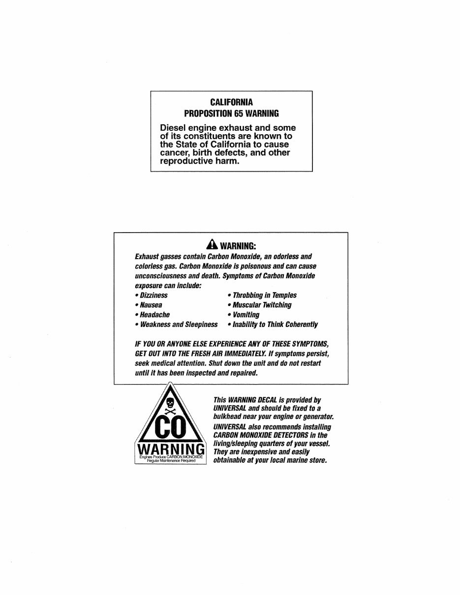
CALIFORNIA
PROPOSITION 65 WARNING
Diesel engine exhaust and some
of its constituents are known to
the State of California to cause
cancer, birth defects, and other
reproductive harm.
A WARNING:
Exhaust gasses contain Carbon Monoxide, an odorless and
colorless gas. Carbon Monoxide is poisonous and can cause
unconsciousness and death. Symptoms of Carbon Monoxide
exposure can Include:
- Dizziness
-Nausea
-Headache
- Throbbing in Temples
- Muscular Twitching
- Vomiting
- Weakness and Sleepiness - Inability to Think Coherently
IF YOU OR ANYONE ELSE EXPERIENCE ANY OF THESE SYMPTOMS,
GET OUT INTO THE FRESH AIR IMMEDIATELY. If symptoms persist,
seek medical attention. Shut down the unit and do not restart
until it has been inspected and repaired.
WARNING
Engines Pn:xIJce CARBON MONOXIDE
Regular Maintenance Required
This WARNING DECAL is provided by
UNIVERSAL and should be fixed to a
bulkhead near your engine or generator.
UNIVERSAL also recommends installing
CARBON MONOXIDE DETECTORS in the
living/sleeping quarters of your vessel.
They are inexpensive and easily
obtainable at your local marine store.
SAFETY INSTRUCTIONS
INTRODUCTION
Read these safety instructions carefully before servicing your
engine. Most accidents are caused by failure to follow
fundamental rules and precautions. Know when dangerous
conditions exist and take the necessary precautions to protect
yourself, your personnel, and your machinery.
The following safety instructions are in compliance with the
American Boat and Yacht Council (ABYC) standards.
PREVENT ELECTRIC SHOCK
A WARNING: Do not touch AC electrical connections
while engine is running, or when connected to shore
power. Lethallloltage is present at these connections!
• Do not operate this m.achinery without electrical
enclosures and covers in place.
• Shut off electrical power before accessing electrical
equipment.
• Use insulated mats whenever working on electrical
equipment.
• Make sure your clothing and skin are dry, not damp
(particularly shoes) when handling electrical equipment.
• Remove wristwatch and all jewelry when working on
electrical equipment.
• Do not connect utility shore power to vessel's AC
circuits, except through a ship-to-shore double throw
transfer switch. Damage to vessel's AC generator may
result if this procedure is not followed.
• Electrical shock results from handling a charged capaci-
tor. Discharge capacitor by shorting terminals together
with an insulated tool.
PREVENT BURNS - HOT ENGINE
A WARNING: Do not touch hot engine parts or
exhaust system components. A running engine gets
lIery hot!
• Always check the engine coolant level at the coolant
recovery tank.
A WARNING: Steam can cause injury or death!
• In case of an engine overheat, allow the engine to cool
before touching the engine or checking the coolant.
PREVENT BURNS - FIRE
A WARNING: Fire can cause injury or death!
• Prevent flash fires. Do not smoke or permit flames or
sparks to occur near the carburetor, fuel line, filter, fuel
pump, or other potential sources of spilled fuel or fuel
vapors. Use a suitable container to catch all fuel when
removing the fuel line, carburetor, or fuel filters.
• Do not operate with a Coast Guard Approved flame
arrester removed. Backfire can cause severe injury or
death.
• Do not operate with the air cleaner/silencer removed.
Backfire can cause severe injury or death.
• Do not smoke or permit flames or sparks to occur near
the fuel system. Keep the compartment and the engine
clean and free of debris to minimize the chance of fire.
Wipe up all spilled fuel and engine oil.
• Be aware - diesel fuel will burn.
PREVENT BURNS - EXPLOSION
A WARNING: Explosions from fuelllapors can cause
injury or death!
• Follow re-fueling safety instructions. Keep the vessel's
hatches closed when fueling. Open and ventilate cabin
after fueling. Check below for fumes/vapor before run-
ning the blower. Run the blower for four minutes before
starting your engine.
• All fuel vapors are highly explosive. Use extreme care
when handling and storing fuels. Store fuel in a well-ven-
tilated area away from spark-producing equipment and
out of the reach of children.
• Do not fill the fuel tank(s) while the engine is running.
• Shut off the fuel service valve at the engine when servicing
the fuel system. Take care in catching any fuel that might
spill. DO NOT allow any smoking, open flames, or other
. sources of fire near the fuel system or engine when servic-
ing. Ensure proper ventilation exists when servicing the
fuel system.
• Do not alter or modify the fuel system.
• Be sure all fuel supplies have a positive shutoff valve.
• Be certain fuel line fittings are adequately tightened and
free of leaks.
• Make sure a fire extinguisher is installed nearby and is
properly maintained. Be familiar with its proper use.
Extinguishers rated ABC by the NFPA are appropriate
for all applications encountered in this environment.
SAFETY INSTRUCTIONS
ACCIDENTAL STARTING
A WARNING: Accidental starting can cause injury
or death!
• Disconnect the battery cables before servicing the engine.
Remove the negative lead first and reconnect it last.
• Make certain all personnel are clear of the engine before
starting.
• Make certain all covers, guards, and hatches are re-
installed before starting the engine.
BATTERY EXPLOSION
A WARNING: Battery explosion can cause injury
or death!
• Do not smoke or allow an open flame near the battery
being serviced. Lead acid batteries emit hydrogen, a
highly explosive gas, which can be ignited by electrical
arcing or by lit tobacco products. Shut off all electrical
equipment in the vicinity to prevent electrical arcing dur-
ing servicing.
• Never connect the negative (-) battery cable to the posi-
tive (+) connection terminal of the starter solenoid. Do
not test the battery condition by shorting the terminals
together. Sparks could ignite battery gases or fuel vapors.
Ventilate any compartment containing batteries to prevent
accumulation of explosive gases. To avoid sparks, do not
disturb the battery charger connections while the battery
is being charged.
• Avoid contacting the terminals with tools, etc., to prevent
bums or sparks that could cause an explosion. Remove
wristwatch, rings, and any other jewelry before handling
the battery.
• Always tum the battery charger off before disconnecting
the battery connections. To avoid sparks from an
accidental short circuit, always remove the negative lead
first and reconnect it last when servicing the battery.
BATTERY ACID
A WARNING: Sulfuric acid In batteries can cause
severe injury or death!
• When servicing the battery or checking the electrolyte
level, wear rubber gloves, a rubber apron, and eye protec-
tion. Batteries contain sulfuric acid which is destructive.
If it comes in contact with your skin, wash it off at once
with water. Acid may splash on the skin or into the eyes
inadvertently when removing electrolyte caps.
TOXIC EXHAUST GASES
A WARNING: Carbon monoxide (CO) is a deadly gas!
• Ensure that the exhaust system is adequate to expel gases
discharged from the engine. Check the exhaust system
regularly for leaks and make sure the exhaust manifolds
are securely attached and no warping exists. Pay close
attention to the manifold, water injection elbow, and
exhaust pipe nipple.
• Be sure the unit and its surroundings are well ventilated.
• In addition to routine inspection of the exhaust system,
install a carbon monoxide detector. Consult your boat
builder or dealer for installation of approved detectors.
• For additional information refer to ABYC T-22 (educa-
tional information on Carbon Monoxide).
A WARNING: Carbon monoxide (CO) is an invisible
odorless gas. Inhalation produces flu-like symptoms,
nausea or death!
• Do not use copper tubing in diesel exhaust systems. Diesel
fumes can rapidly destroy copper tubing in exhaust sys-
tems. Exhaust sulfur causes rapid deterioration of copper
tubing resulting in exhaust/water leakage.
• Do not install exhaust outlet where exhaust can be drawn
through portholes, vents, or air conditioners. If .the engine
exhaust discharge outlet is near the waterline, water could
enter the exhaust discharge outlet and close or restrict the
flow of exhaust. Avoid overloading the craft.
• Although diesel engine exhaust gases are not as 10xic as
exhaust fumes from gasoline engines, carbon monoxide
gas is present in diesel exhaust fumes. Some of the symp-
toms or signs of carbon monoxide inhalation or poisoning
are:
Dizziness
Headache
Nausea
Vomiting
Throbbing in temples
Muscular twitching
Weakness and sleepiness
Inability to think coherently
AVOID MOVING PARTS
A WARNING: Rotating parts can cause Injury
or death!
• Do not service the engine while it is running. If a situa-
tion arises in which it is absolutely necessary to make
operating adjustments, use extreme care to avoid touching
moving parts and hot exhaust system components.
SAFETY INSTRUCTIONS
• Do not wear loose clothing or jewelry when servicing
equipment; tie back long hair and avoid wearing loose
jackets, shirts, sleeves, rings, necklaces or bracelets that
could be caught in moving parts.
• Make sure all attaching hardware is properly tightened.
Keep protective shields and guards in their respective
places at all times.
• Do not check fluid levels or the drive belt's tension while
the engine is operating.
• Stay clear of the drive shaft and the transmission coupling
when the engine is running; hair and clothing can easily
be caught in these rotating parts.
HAZARDOUS NOISE
A WARNING: High noise levels can cause hearing
loss!
• Never operate an engine without its muffler installed.
• Do not run an engine with the air intake (silencer)
removed.
• Do not run engines for long periods with their enclosures
open.
A WARNING: Do not work on machinery when you are
mentally or physically incapacitated by fatigue!
OPERATORS MANUAL
Many of the preceding safety tips and warnings are repeated
in your Operators Manual along with other cautions and
notes to highlight critical information. Read your manual
carefully, maintain your equipment, and follow all safety
procedures.
ENGINE INSTALLATIONS
Preparations to install an engine should begin with a thor-
ough examination of the American Boat and Yacht Council's
(ABYC) standards. These standards are a combination of
sources including the USCG and the NFPA.
Sections of the ABYC standards of particular interest are:
H-2 Ventilation
P-l Exhaust systems
P-4 Inboard engines
E-9 DC Electrical systems
All installations must comply with the Federal Code of
Regulations (FCR).
iii
ABYC, NFPA AND USCG PUBLICATIONS FOR
INSTALLING DIESEL ENGINES
Read the following ABYC, NFPA and USCG publications
for safety codes and standards. Follow their recommenda-
tions when installing your engine.
ABYC (American Boat and Yacht Council)
Safety Standards for Small Craft
Order from:
ABYC
3069 Solomons Island Rd.
Edgewater, MD 21037
NFPA (National Fire Protection Association)
Fire Protection Standardfor Motor Craft
Order from:
NFPA
11 Tracy Drive
Avon Industrial Park
Avon, MA 02322
USCG (United States Coast Guard)
USCG 33CFR183
Order from:
U.S. Government Printing Office
Washington, D.C. 20404
INSTALLATION
When installing UNIVERSAL engines, it is important that strict attention be paid
to the following information:
CODES AND REGULATIONS
Federal regulations, ABYC guidelines and safety codes must be complied with
when installing engines and generators in a marine environment.
SIPHON-BREAK
For installations where the exhaust manifold/water-injected exhaust elbow is close
to or will be below the vessel's waterline, provisions must be made to install a
siphon-break in the raw water supply hose to the exhaust elbow. This hose must
be looped a minimum of 20 in (51 em) above the vessel's waterline. Failure to
use a siphon-break when the exhaust manifold injection pori is at or below the
load waterline will result in raw water damage to the engine and possible flood-
ing of the boat.
If you have any doubt about the position of the water-injected exhaust elbow rela-
tive to the vessel's waterline under any of the vessel's various operating conditions
or when the vessel is not underway, install a siphon-break. This precaution is
necessary to protect your engine.
NOTE: A siphon-break requires periodic inspection and cleaning to ensure proper
operation. Failure to properly maintain a siphon-break can result in catastrophic
engine damage. Consult the siphon-break manufacturer for a proper maintenance
schedule.
EXHAUST SYSTEM
The exhaust hose must be certified for marine use. The system must be designed
to prevent water from entering the exhaust under any sea conditions and at any
angle of the vessel's hull.
A detailed 40-page Marine Installation Manual covering gasoline and
diesel, engines and generators, is available from your UNIVERSAL dealer.
iv
TABLE OF CONTENTS
Introduction .......................................................................................................... 2
Parts Identification...................... :........................................................................ 3
Specifications ....................................................................................................... 4
Testing for OverhauL ........................................................................................... 6
Engine Troubleshooting ....................................................................................... 7
Service Standards ............................................................................................... 15
Engine Description............................................................................................. 18
Engine Disassembly & Reassembly................................................................... 21
Engine Service................................................................................................... 32
Engine Adjustments ........................................................................................... .43
Exhaust Manifold Service .................................................................................. 47
Lubrication System Description......................................................................... 48
Lubrication System Service............................................................................... 50
Cooling System Description.............................................................................. 52
Cooling System Service..................................................................................... 54
Fuel System Description.................................................................................... 56
Fuel System Disassembly & Reassembly.......................................................... 60
Fuel System Service........................................................................................... 61
Admiral Control PaneL ...................................................................................... 63
Captain Control PaneL ....................................................................................... 64
Control Panel Troubleshooting .......................................................................... 65
Glow Plug Service............................................................................................. 67
Starter Service.................................................................................................... 68
Mando Alternator Service.................................................................................. 72
Prestolite Alternator Service.............................................................................. 82
Wiring Diagram #39144 .................................................................................... 94
Wiring Schematic #39144 .................................................................................. 95
Wiring Diagram #200360 - Catalina yachts ..................................................... 96
Wiring Schematic #200360 - Catalina Yachts ................................................... 97
Hurth HBW Transmissions. ............. ........... .......... ........ .......... .............. ........... 98
Transmission Troubleshooting ......................................................................... 101
Special Tools .................................................................................................... 102
Torques ............................................................................................................. 104
Standard Hardware; Sealants & Lubricants ..................................................... 105
Metric Conversions .......................................................................................... 106
Standard and Metric Conversion Data............................................................. 107
Index ................................................................................................................. 108
it itUnlvarsal
32 1'&'i J @jijeiW3i-
1
INTRODUCTION
ENGINE OVERHAUL
This service manual contains detailed information relating
to the servicing and overhaul of the Universal M-25XPB,
M-35B and M-40B marine diesel engines. Information
about the construction and function of the various systems
and components can be found in the Description sections.
For the major engine overhaul procedure, refer to the
ENGINE DISASSEMBLY & REASSEMBLY and ENGINE
SERVICE sections. Additional service information for spe-
cific components and systems may be found by referring to
the TABLE OF CONTENTS and the INDEX. Refer also to
your UNIVERSAL parts Catalog.
These service procedures are intended for the guidance of
suitably equipped and staffed marine engine service and
rebuilding facilities, and should only be undertaken by such
facilities and their personnel.
The service information in this manual generally applies to
all three models covered by this manual. The individual
models will only be noted where information does not apply
to all three models.
PRODUCT SOFTWARE
Product software (tech data, parts lists, manuals, brochures
and catalogs) provided from sources other than UNIVER-
SAL are not within UNIVERSAL'S CONTROL.
UNIVERSAL CANNOT BE RESPONSIBLE FOR THE
CONTENT OF SUCH SOFTWARE, MAKES NO WAR-
RANTIES OR REPRESENTATIONS WITH RESPECT
THERETO, INCLUDING ACCURACY, TIMELINESS OR
COMPLETENESS THEREOF AND WILL IN NO EVENT
BE LIABLE FOR ANY TYPE OF DAMAGE OR INJURY
INCURRED IN CONNECTION WITH OR ARISING OUT
OF THE FURNISHING OR USE OF SUCH SOFTWARE.
UNIVERSAL customers should also keep in mind the time
span between printings of UNIVERSAL product software
and the unavoidable existence of earlier UNIVERSAL manu-
als. Product software provided with UNIVERSAL products,
whether from UNIVERSAL or other suppliers, must not and
cannot be relied upon exclusively as the definitive authority
on the respective product. It not only makes good sense but
is imperative that appropriate representatives of UNIVER-
SAL or the supplier in question be consulted to determine
the accuracy and currentness of the product software being
consulted by the customer.
NOTES, CAUTIONS AND WARNINGS
As this manual takes you through the service procedures
and troubleshooting of your marine engine, critical informa-
tion will be highlighted by NOTES, CAUTIONS, and WARN-
INGS. An explanation follows:
NOTE: An operating procedure essential to note.
A CAUTION: Procedures, which if not strictly
observed, can result in the damage or destruction of
your engine.
2
A WARNING: Procedures, which if not properly fol-
lowed, can result in personal injury or loss of life.
CUSTOMER IDENTIFICATION CARD
Customer Identification
UNIVERSAL OWNER
MAIN STREET
HOMETOWN, USA
Model M-358 Ser. #XXXX-D704
Expires 4/24/01
The UNIVERSAL engine serial number is an alphanumeric
number that can assist in determining the date of manufac-
ture of your UNIVERSAL engine. The manufacturer's date
code is placed at the end of the engine serial number and
consists of a character followed by three numbers. The
character indicates the decade (D=1990s, E=2000s), the first
number represents the year in the decade, and the second
and third numbers represent the month of manufacture.
ORDERING PARTS/SERIAL NUMBER LOCATION
Whenever replacement parts are needed, always provide
the engine model number and engine serial number as they
appear on the silver and black identification nameplate
located on the side of the engine's exhaust manifold. The
engine serial number can also be found stamped into the
engine block on the left side of the engine below the cylin-
der head cover. You must provide us with this information
so we may properly identify your engine. In addition,
include a complete part description and part number for
each part needed (see the separately furnished Parts List).
Also insist upon UNIVERSAL packaged parts because will
fit or generic parts are frequently not made to the same
specifications as original equipment.
NOTE: Component locations in this manual are referenced
from the front of the engine which is the pulley/drive belt
end. Left and right sides are determined as follows: imag-
ine straddling the engine, facing in the same direction as
the front of the engine: the left side is at your left, the right
side is at your right. The cylinder number sequence starts
with the No.1 cylinder located at the front of the engine.
TRANSMISSION
CONTROL
BRACKET
TRANSMISSION
CONTROL
BRACKET
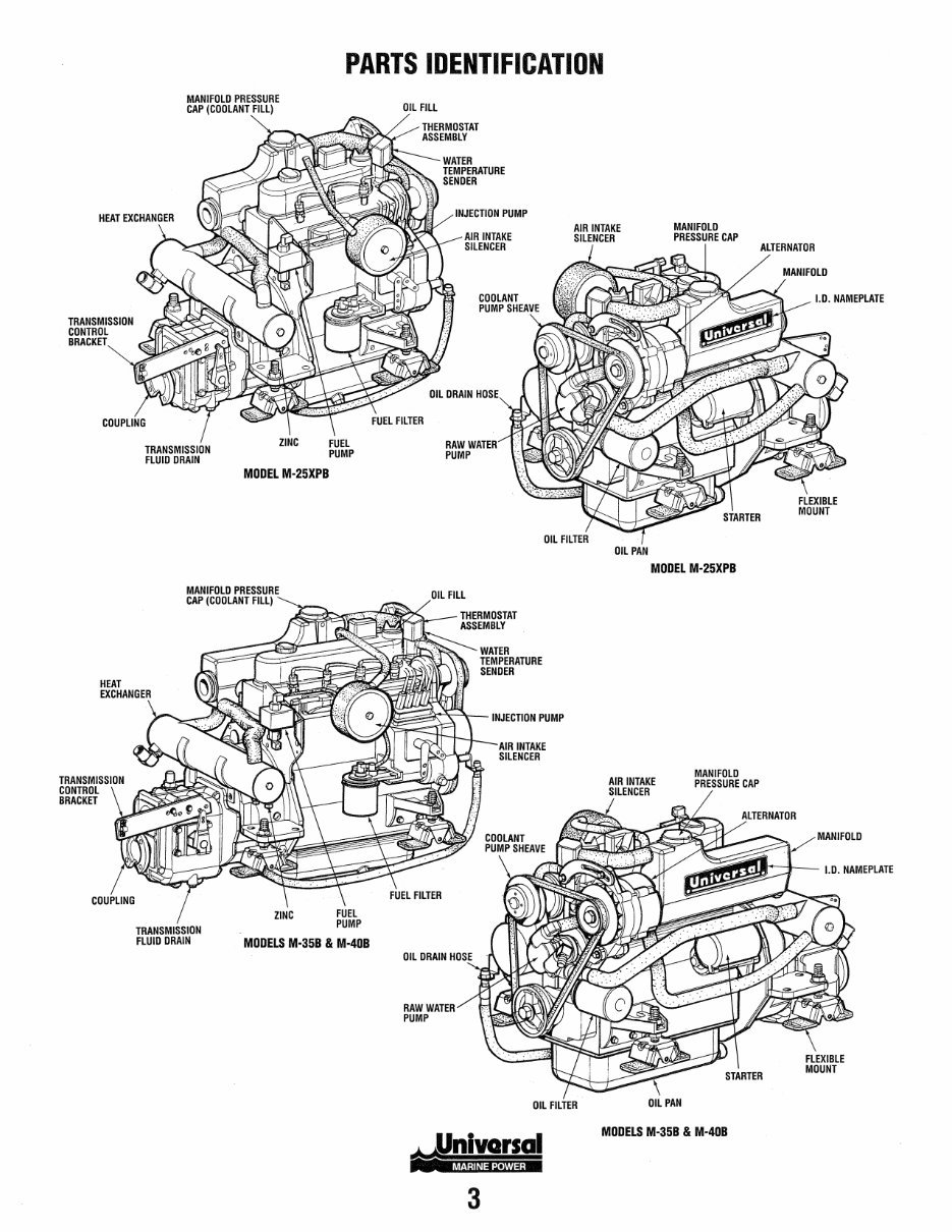
PARTS IDENTIFICATION
MANIFOLD PRESSURE
CAP (COOLANT FILL)
TRANSMISSION
FLUID DRAIN
MODEL M-25XPB
MANIFOLD PRESSURE
CAP (COOLANT FILL)
TRANSMISSION
FLUID DRAIN
MODELS M-35B & M-40B
OIL FILL
THERMOSTAT
ASSEMBLY
INJECTION PUMP
AIR INTAKE
SILENCER
RAW
PUMP
INJECTION PUMP
OIL DRAIN
RAW WATER
PUMP
AIR INTAKE
SILENCER
AIR INTAKE
SILENCER
OIL PAN
MANIFOLD
PRESSURE CAP
MODEL M-25XPB
AIR INTAKE
SILENCER
MANIFOLD
PRESSURE CAP
ALTERNATOR
I.D. NAMEPLATE
MANIFOLD
I.D. NAMEPLATE
OIL FILTER
OIL PAN
MODELS M-35B & M-40B
3
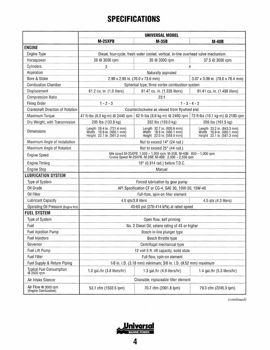
SPECIFICATIONS
UNIVERSAL MODEL
M-25XPB M·35B M-40B
ENGINE
Engine Type Diesel, four-cycle, fresh water cooled, vertical, in-line overhead valve mechanism
Horsepower 26 @ 3000 rpm 35 @ 3000 rpm 37.5 @ 3000 rpm
Cylinders 3
I
4
Aspiration Naturally aspirated
Bore & Stoke 2.99 x 2.90 in. (76.0 x 73.6 mm) 3.07 x 3.09 in. (78.0 x 78.4 mm)
Combustion Chamber Spherical type; three vortex combustion system
Displacement 61.2 cu. in. (1.0 liters) 81.47 cu. in. (1.335 liters) 91.41 cu. in. (1.498 liters)
Compression Ratio 23:1
Firing Order 1 - 2 - 3 1-3-4-2
Crankshaft Direction of Rotation Counterclockwise as viewed from flywheel end
Maximum Torque 47 ft-Ibs (6.5 kg-m) @ 2440 rpm 62 ft-Ibs (8.6 kg-m) @ 2460 rpm 73 ft-Ibs (10.1 kg-m) @ 2180 rpm
Dry Weight, with Transmission 295 Ibs (133.8 kg) 352 Ibs (159.0 kg) 356 Ibs (161.5 kg)
Dimensions
Length 28.4 in. 1721.4 mml Length 32.7 in. t 30 .6 mml Length 33.2 in. (843.3 mml
Width 18.9 in. 4BO.1 mm Width 1B.9 in. 480.1 mm Width 18.9 in. 14BO.1 mm
Height 22.1 in. 561.3 mm Height 22.0 in. 55B.9 mm Height 22.1 in. 561.3 mm
Maximum Angle of Installation Not to exceed 14° (24 rad.)
Maximum Angle of Rotation Not to exceed 25° (44 rad.)
Engine Speed
Idle speed M-25XPB: 1,000 - 1,200 rpm; M-35B, M-40B: BOO - 1,000 rpm
Cruise Speed M-25XPB, M-35B, M-40B: 2,000 - 2,500 rpm
Engine Timing 18° (0.314 rad.) before lD.C.
Engine Stop Manual
LUBRICATION SYSTEM
Type of System Forced lubrication by gear pump
Oil Grade API Specification CF or CG-4, SAE 30, 10W-30, 15W-40
Oil Filter Full-flow, spin-on filter element
Lubricant Capacity 4.0 qts/3.8 liters 4.5 qts (4.3 liters)
Operating Oil Pressure (Engine Hot) 40-60 psi (276-414 kPa) at rated speed
FUEL SYSTEM
Type of System Open flow, self priming
Fuel No.2 Diesel Oil, cetane rating of 45 or higher
Fuel Injection Pump Bosch in-line plunger type
Fuel Injectors Bosch throttle type
Governor Centrifugal mechanical type
Fuel Lift Pump 12 volt 5 ft. lift capacity, solid state
Fuel Filter Full flow, spin-on element
Fuel Supply & Return Piping 1/8 in. 1.0. (3.18 mm) minimum; 3/8 in. 1.0. (9.52 mm) maximum
Typical Fuel Consumption
@2500 rpm
1.0 gal.lhr (3.8 liters/hr) 1.3 gal.lhr (4.9 liters/hr) 1.4 gal.lhr (5.3 liters/hr)
Air Intake Silencer Cleanable, replaceable filter element
Air Flow @ 3000 rpm
53.1 cfm (1503.5 Ipm) 70.7 cfm (2001.8 Ipm) 79.3 cfm (2245.3 Ipm)
(Engine Combustion)
(continued)
4
You're Reading a Preview
What's Included?
 Lifetime Access
Fast Download Speeds
Online & Offline Access
Access PDF Contents & Bookmarks
Full Search Facility
Print one or all pages of your manual
$41.99
WESTERBEKE Universal Marine Diesel EngineS M-25XPB M-35B M-40B Service Repair Manual !
Viewed 24 Times Today

What's Included?
Lifetime Access
Fast Download Speeds
Online & Offline Access
Access PDF Contents & Bookmarks
Full Search Facility
Print one or all pages of your manual
$41.99

Secure transaction
What's Included?
Lifetime Access
Fast Download Speeds
Online & Offline Access
Access PDF Contents & Bookmarks
Full Search Facility
Print one or all pages of your manual
Description
This service repair manual is designed for the maintenance and repair of WESTERBEKE Universal MARINE DIESEL ENGINES M-25XPB, M-35B, and M-40B. It provides step-by-step instructions, detailed diagrams, and illustrations to facilitate DIY enthusiasts and professional mechanics in performing maintenance, service, diagnosis, and repairs.
- Introduction
- Parts Identification
- Specifications
- Testing for Overhaul
- Engine Troubleshooting
- Service Standards
- Engine Description
- Engine Disassembly & Reassembly
- Engine Service
- Engine Adjustments
- Exhaust Manifold Service
- Lubrication System Description
- Lubrication System Service
- Cooling System Description
- Cooling System Service
- Fuel System Description
- Fuel System Disassembly & Reassembly
- Fuel System Service
- Admiral Control Panel
- Captain Control Panel
- Control Panel Troubleshooting
- Glow Plug Service
- Starter Service
- Mando Alternator Service
- Prestolite Alternator Service
- Wiring Diagram #39144
- Wiring Schematic #39144
- Wiring Diagram #200360 - Catalina yachts
- Wiring Schematic #200360 - Catalina Yachts
- Hurth HBW Transmissions
- Transmission Troubleshooting
- Special Tools
- Torques
- Standard Hardware; Sealants & Lubricants
- Metric Conversions
- Standard and Metric Conversion Data
- Index
This manual is available in .PDF format and can be accessed on all versions of Windows and Mac. It requires Adobe Reader and Win for viewing. Instant delivery eliminates shipping costs and waiting time, allowing immediate access upon secure payment completion. The manual is printable for convenience.


