

WESTERBEKE L25 Marine Diesel Engine Service Repair Technical Manual !
What's Included?
Fast Download Speeds
Online & Offline Access
Access PDF Contents & Bookmarks
Full Search Facility
Print one or all pages of your manual

TECHNICAL MANUAL
WESTERBEKE L25
Marine Diesel Engine
PUBLICATION 19419
EDITION 3
MAY 1978
'WESTERBEKE
J WESTERBEKECORPORATION
• MYLES STANDISH INDUSTRIAL PARK
150 JOHN HANCOCK ROAD, TAUNTON, MA 02780-7319
Downloaded from www.Manualslib.com manuals search engine
TECHNICAL MANUAL
WESTERBEKE L25
Marine Diesel Engine
PUBLICATION 19419
EDITION 3
MAY 1978
'WESTERBEKE
J WESTERBEKECORPORATION
• MYLES STANDISH INDUSTRIAL PARK
150 JOHN HANCOCK ROAD, TAUNTON, MA 02780-7319
Downloaded from www.Manualslib.com manuals search engine
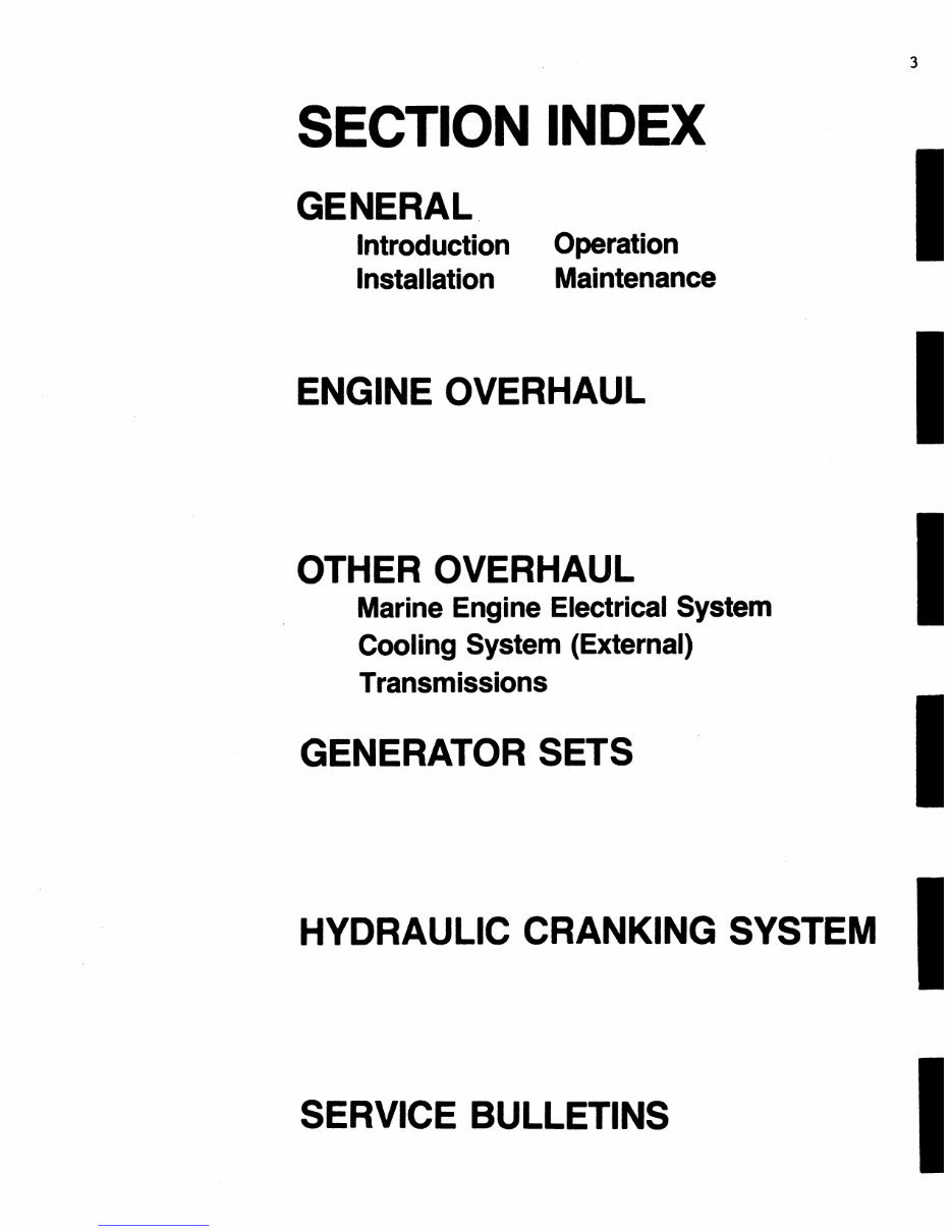
SECTION INDEX
GENERAL.
Introduction Operation
Installation Maintenance
ENGINE OVERHAUL
OTHER OVERHAUL
Marine Engine Electrical System
Cooling System (External)
Transmissions
GENERATOR SETS
HYDRAULIC CRANKING SYSTEM
SERVICE BULLETINS
3
Downloaded from www.Manualslib.com manuals search engine

4
YOUR NOTES
Downloaded from www.Manualslib.com manuals search engine
INTRODUCTION
5
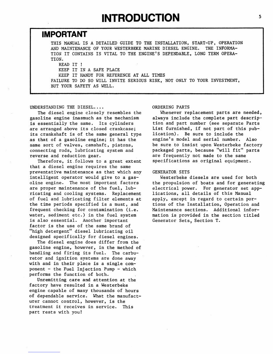
IMPORTANT
THIS MANUAL IS A DETAILED GUIDE TO THE INSTALLATION, START-UP, OPERATION
AND MAINTENANCE OF YOUR WESTERBEKE MARINE DIESEL ENGINE. THE INFORMA-
TION IT CONTAINS IS VITAL TO THE ENGINE'S DEPENDABLE, LONG TERM OPERA-
TION.
READ IT
KEEP IT IN A SAFE PLACE
KEEP IT HANDY FOR REFERENCE AT ALL TIMES
FAILURE TO DO SO WILL INVITE SERIOUS RISK, NOT ONLY TO YOUR INVESTMENT,
BUT YOUR SAFETY AS WELL.
UNDERSTANDING THE DIESEL ••••
The diesel engine closely resembles the
gasoline engine inasmuch as the mechanism
is essentially the same. Its cylinders
are arranged above its closed crankcase;
its crankshaft is of the same general type
as that of a gasoline engine; it has the
same sort of valves, camshaft, pistons,
connecting rods, lubricating system and
reverse and reduction gear.
Therefore, it.follows to a great extent
that a diesel engine requires the same
preventative maintenance as that which any
intelligent operator would give to a gas-
oline engine. The most important factors
are proper maintenance of the fuel, lub-
ricating and cooling systems. Replacement
of fuel and lubricating filter elements at
the time periods specified is a must, and
frequent checking for contamination (i.e.
water, sediment etc.) in the fuel system
is also essential. Another important
factor is the use of the same brand of
"high detergent" diesel lubricating oil
designed specifically for diesel engines.
The diesel engine does differ from the
gasoline engine, however, in the method of
handling and firing its fuel. The carbu-
retor and ignition systems are done away
with and in their place is a single com-
ponent - the Fuel Injection Pump - which
performs the function of both.
Unremitting care and attention at the
factory have resulted in a Westerbeke
engine capable of many thousands of hours
of dependable service. What the manufact-
urer cannot control, however, is the
treatment it receives in service. This
part rests with you!
ORDERING PARTS
Whenever replacement parts are needed,
always include the complete part descrip-
tion and part number (see separate Parts
List furnished, if not part of this pub-
lication). Be sure to include the
engine's model and serial number. Also
be sure to insist upon Westerbeke factory
packaged parts, because "will fit" parts
are frequently not made to the same
specifications as original equipment.
GENERATOR SETS
Westerbeke diesels are used for both
the propulsion of boats and for generating
electrical power. For generator set app-
lications, all details of this Manual
apply, except in regard to certain por-
tions of the Installation, Operation and
Maintenance sections. Additional infor-
mation is provided in the section titled
Generator Sets, Section T.
Downloaded from www.Manualslib.com manuals search engine

Downloaded from www.Manualslib.com manuals search engine
INSTALLATION
7
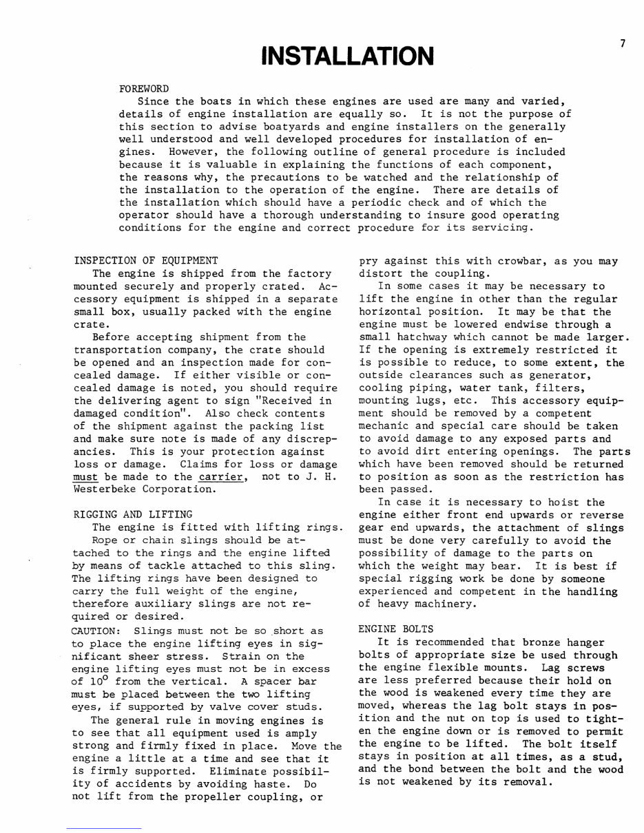
FOREWORD
Since the boats in which these engines are used are many and varied,
details of engine installation are equally so. It is not the purpose of
this section to advise boatyards and engine installers on the generally
well understood and well developed procedures for installation of en-
gines. However, the following outline of general procedure is included
because it is valuable in explaining the functions of each component,
the reasons why, the precautions to be watched and the relationship of
the installation to the operation of the engine. There are details of
the installation which should have a periodic check and of which the
operator should have a thorough understanding to insure good operating
conditions for the engine and correct procedure for its servicing.
INSPECTION OF EQUIPMENT
The engine is shipped from the factory
mounted securely and properly crated. Ac-
cessory equipment is shipped in a separate
small box, usually packed with the engine
crate.
Before accepting shipment from the
transportation company, the crate should
be opened and an inspection made for con-
cealed damage. If either visible or con-
cealed damage is noted, you should require
the delivering agent to sign "Received in
damaged condition". Also check contents
of the shipment against the packing list
and make sure note is made of any discrep-
ancies. This is your protection against
loss or damage. Claims for loss or damage
must be made to the carrier, not to J. H.
Westerbeke Corporation.
RIGGING AND LIFTING
The engine is fitted with lifting rings.
Rope or chain slings should be at-
tached to the rings and the engine lifted
by means of tackle attached to this sling.
The lifting rings have been designed to
carry the full weight of the engine,
therefore auxiliary slings are not re-
quired or desired.
CAUTION: Slings must not be so .short as
to place the engine lifting eyes in sig-
nificant sheer stress. Strain on the
engine lifting eyes must not be in excess
of 100 from the vertical. A spacer bar
must be placed between the two lifting
eyes, if supported by valve cover studs.
The general rule in moving engines is
to see that all equipment used is amply
strong and firmly fixed in place. Move the
engine a little at a time and see that it
is firmly supported. Eliminate possibil-
ity of accidents by avoiding haste. Do
not lift from the propeller coupling, or
pry against this with crowbar, as you may
distort the coupling.
In some cases it may be necessary to
lift the engine in other than the regular
horizontal position. It may be that the
engine must be lowered endwise through a
small hatchway which cannot be made larger.
If the opening is extremely restricted it
is possible to reduce, to some extent, the
outside clearances such as generator,
cooling piping, water tank, filters,
mounting lugs, etc. This accessory equip-
ment should be removed by a competent
mechanic and special care should be taken
to avoid damage to any exposed parts and
to avoid dirt entering openings. The parts
which have been removed should be returned
to position as soon as the restriction has
been passed.
In case it is necessary to hoist the
engine either front end upwards or reverse
gear .end upwards, the attachment of slings
must be done very carefully to avoid the
possibility of damage to the parts on
which the weight may bear. It is best if
special rigging work be done by someone
experienced and competent in the handling
of heavy machinery.
ENGINE BOLTS
It is recommended that bronze hanger
bolts of appropriate size be used through
the engine flexible mounts. Lag screws
are less preferred because their hold on
the wood is weakened every time they are
moved, whereas the lag bolt stays in pos-
ition and the nut on top is used to tight-
en the engine down or is removed to permit
the engine to be lifted. The bolt itself
stays in position at all times, as a stud,
and the bond between the bolt and the wood
is not weakened by its removal.
Downloaded from www.Manualslib.com manuals search engine
8
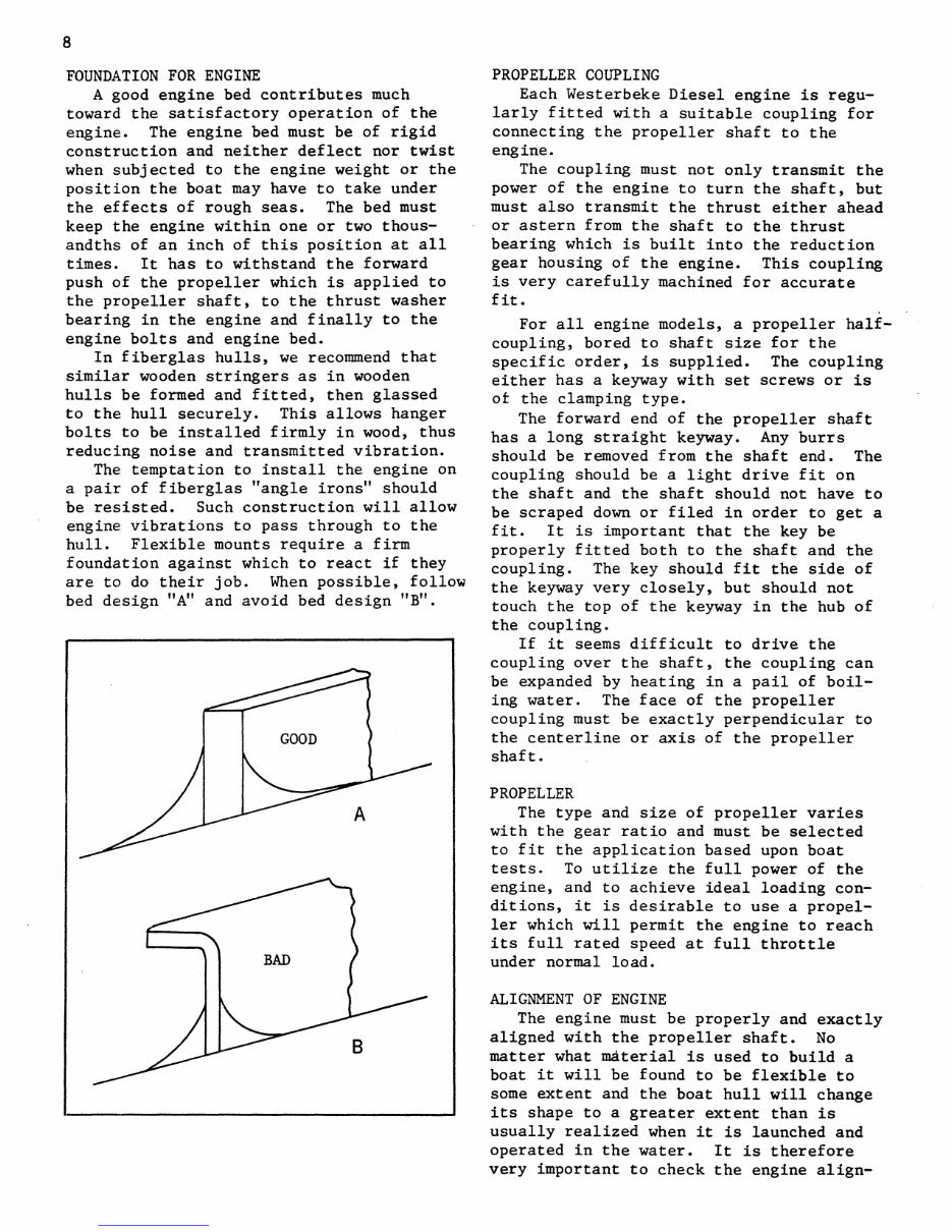
FOUNDATION FOR ENGINE
A good engine bed contributes much
toward the satisfactory operation of the
engine. The engine bed must be of rigid
construction and neither deflect nor twist
when subjected to the engine weight or the
position the boat may have to take under
the effects of rough seas. The bed must
keep the engine within one or two thous-
andths of an inch of this position at all
times. It has to withstand the forward
push of the propeller which is applied to
the propeller shaft, to the thrust washer
bearing in the engine and finally to the
engine bolts and engine bed.
In fiberglas hulls, we recommend that
similar wooden stringers as in wooden
hulls be formed and fitted, then glassed
to the hull securely. This allows hanger
bolts to be installed firmly in wood, thus
reducing noise and transmitted vibration.
The temptation to install the engine on
a pair of fiberglas "angle irons" should
be resisted. Such construction will allow
engine vibrations to pass through to the
hull. Flexible mounts require a firm
foundation against which to react if they
are to do their job. When possible, follow
bed design "A" and avoid bed design "B".
PROPELLER COUPLING
Each Westerbeke Diesel engine is regu-
larly fitted with a suitable coupling for
connecting the propeller shaft to the
engine.
The coupling must not only transmit the
power of the engine to turn the shaft, but
must also transmit the thrust either ahead
or astern from the shaft to the thrust
bearing which is built into the reduction
gear housing of the engine. This coupling
is very carefully machined for accurate
fit.
For all engine models, a propeller half-
coupling, bored to shaft size for the
specific order, is supplied. The coupling
either has a keyway with set screws or is
ot the clamping type.
The forward end of the propeller shaft
has a long straight keyway. Any burrs
should be removed from the shaft end. The
coupling should be a light drive fit on
the shaft and the shaft should not have to
be scraped down or filed in order to get a
fit. It is important that the key be
properly fitted both to the shaft and the
coupling. The key should fit the side of
the keyway very closely, but should not
touch the top of the keyway in the hub of
the coupling.
If it seems difficult to drive the
coupling over the shaft, the coupling can
be expanded by heating in a pail of boil-
ing water. The face of the propeller
coupling must be exactly perpendicular to
the centerline or axis of the propeller
shaft.
PROPELLER
The type and size of propeller varies
with the gear ratio and must be selected
to fit the application based upon boat
tests. To utilize the full power of the
engine, and to achieve ideal loading con-
ditions, it is desirable to use a propel-
ler which will permit the engine to reach
its full rated speed at full throttle
under normal load.
ALIGNMENT OF ENGINE
The engine must be properly and exactly
aligned with the propeller shaft. No
matter what material is used to build a
boat it will be found to be flexible to
some extent and the boat hull will change
its shape to a greater extent than is
usually realized when it is launched and
operated in the water. It is therefore
very important to check the engine align-
Downloaded from www.Manualslib.com manuals search engine
ment at frequent intervals and to correct
any errors when they may appear.
Misalignment between the engine and the
propeller shaft is the cause of troubles
which are blamed often on other causes.
It will create excessive bearing wear,
rapid shaft wear and will, in many cases,
reduce the life of the hull by loosening.
the hull fastenings. A bent propeller
shaft will have exactly the same effect
and it is therefore necessary that the
propeller shaft itself be perfectly
straight.
One particularly annoying result of mis-
alignment may be leakage of transmission
oil through the rear oil seal. Check to
make sure that alignment is within the
limits prescribed.
The engine should be moved around on
the bed and supported on the screw-jacks
or shims until the two halves of the coup-
lings can be brought together without using
force and so that the flanges meet evenly
all around. It is best not to drill the
foundation for the foundation bolts until
the approximate alignment has been accu-
rately determined.
Never attempt a final alignment with
the boat on land. The boat should be in
the water and have had an opportunity to
assume its final water form. It is best
to do the alignment with the fuel and
water tank about half full and all the
usual equipment on board and after the
main mast has been stepped and final rig-
ging has been accomplished.
Take .plenty of time in making this
alignment and do not be satisfied with
anything less than perfect results.
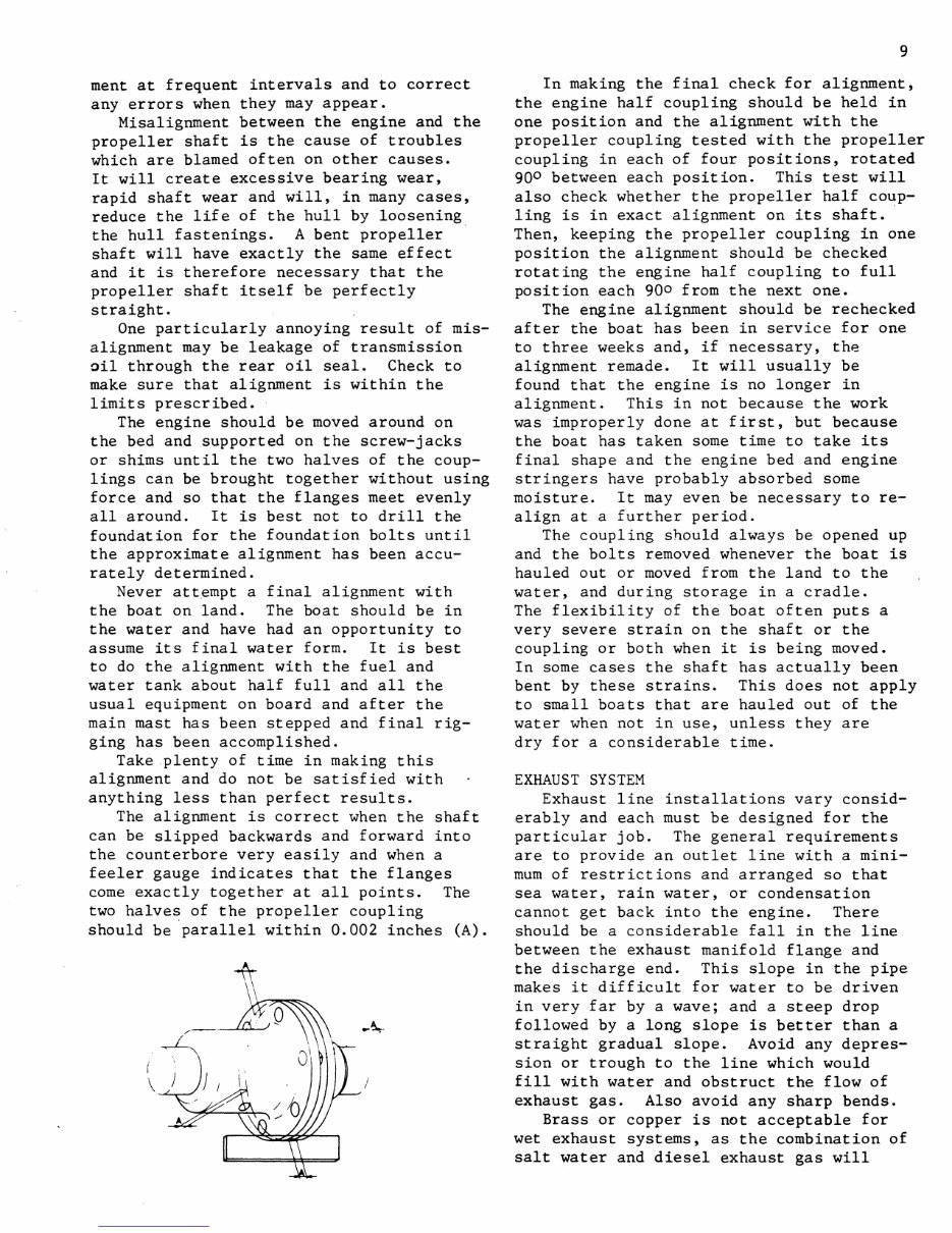
The alignment is correct when the shaft
can be slipped backwards and forward into
the counterbore very easily and when a
feeler gauge indicates that the flanges
come exactly together at all points. The
two halves of the propeller coupling
should be parallel within 0.002 inches (A).
i
\
..
9
In making the final check for alignment,
the engine half coupling should be held in
one position and the alignment with the
propeller coupling tested with the propeller
coupling in each of four positions, rotated
90 0 between each position. This test will
also check whether the propeller half coup-
ling is in exact alignment on its shaft ..
Then, keeping the propeller coupling in one
position the alignment should be checked
rotating the engine half coupling to full
position each 900 from the next one.
The engine alignment should be rechecked
after the boat has been in service for one
to three weeks and, if necessary, the
alignment remade. It will usually be
found that the engine is no longer in
alignment. This in not because the work
was improperly done at first, but because
the boat has taken some time to take its
final shape and the engine bed and engine
stringers have probably absorbed some
moisture. It may even be necessary to re-
align at a further period.
The coupling should always be opened up
and the bolts removed whenever the boat is
hauled out or moved from the land to the
water, and during storage in a cradle.
The flexibility of the boat often puts a
very severe strain on the shaft or the
coupling or both when it is being moved.
In some cases the shaft has actually been
bent by these strains. This does not apply
to small boats that are hauled out of the
water when not in use, unless they are
dry for a considerable time.
EXHAUST SYSTEM
Exhaust line installations vary consid-
erably and each must be designed for the
particular job. The general requirements
are to provide an outlet line with a mini-
mum of restrictions and arranged so that
sea water, rain water, or condensation
cannot get back into the engine. There
should be a considerable fall in the line
between the exhaust manifold flange and
the discharge end. This slope in the pipe
makes it difficult for water to be driven
in very far by a wave; and a steep drop
followed by a long slope is better than a
straight gradual slope. Avoid any depres-
sion or trough to the line which would
fill with water and obstruct the flow of
exhaust gas. Also avoid any sharp bends.
Brass or copper is not acceptable for
wet exhaust systems, as the combination of
salt water and diesel exhaust gas will
Downloaded from www.Manualslib.com manuals search engine
10
cause rapid deterioration. Galvanized
iron fittings and galvanized iron pipe is
recommended for the exhaust line. The ex-
haust line must be at least as large as
the engine exhaust manifold flange and be
increased in size if there is an especial-
ly long run and/or many elbows. It should
be increased by 1/2" in LD. for every 10
feet beyond the first 10 feet.
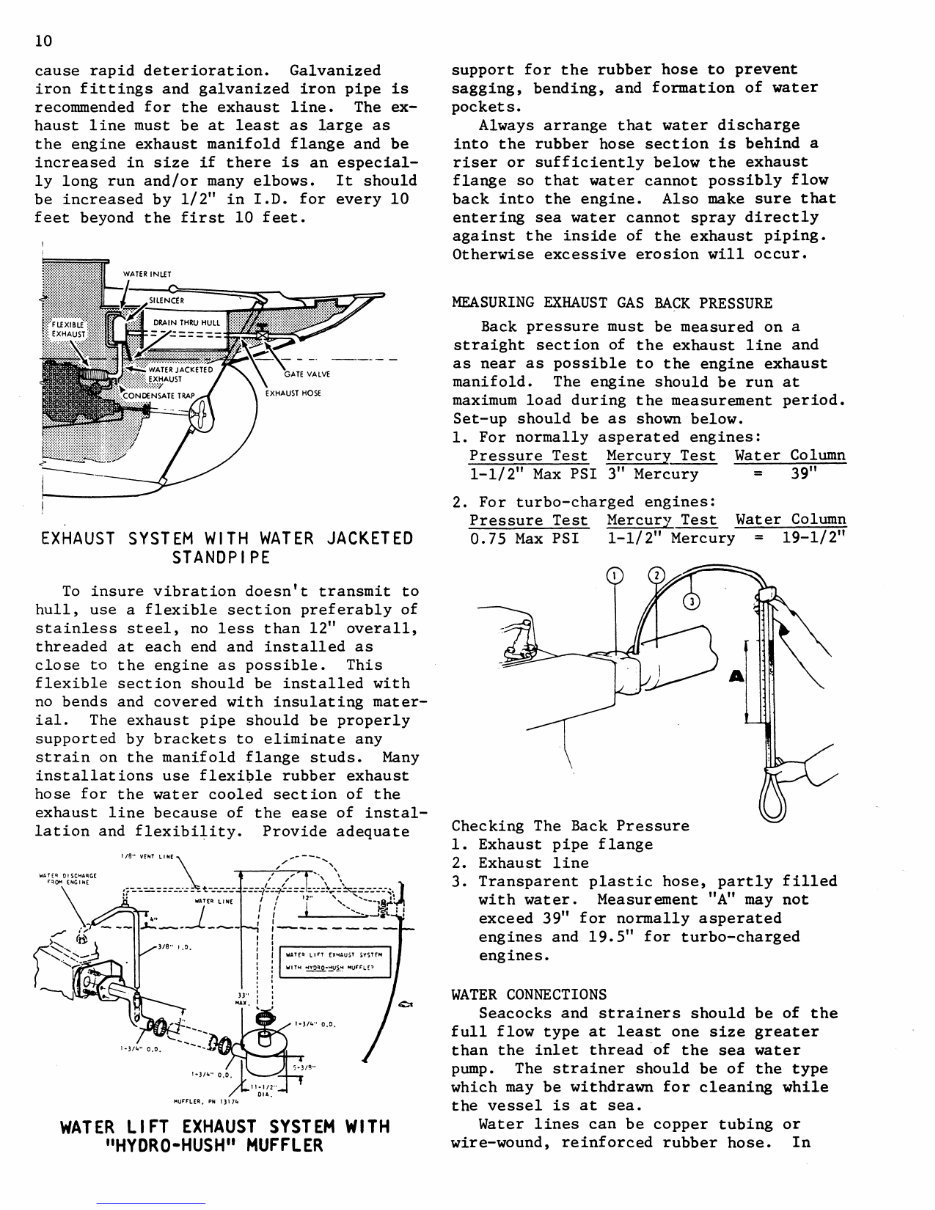
EXHAUST SYSTEM WITH WATER JACKETED
STANDPIPE
To insure vibration doesn't transmit to
hull, use a flexible section preferably of
stainless steel, no less than 12" overall,
threaded at each end and installed as
close to the engine as possible. This
flexible section should be installed with
no bends and covered with insulating mater-
ial. The exhaust pipe should be properly
supported by brackets to eliminate any
strain on the manifold flange studs. Many
installations use flexible rubber exhaust
hose for the water cooled section of the
exhaust line because of the ease of instal-
lation and flexibility. Provide adequate
1-)/10" 0.0,
,-''''. ___ !--...
11·1/2"
OIA.
MUF'FLEA., PH 1)1710
WATER LIFT EXHAUST SYSTEM WITH
"HYDRO-HUSH" MUFFLER
support for the rubber hose to prevent
sagging, bending, and formation of water
pockets.
Always arrange that water discharge
into the rubber hose section is behind a
riser or sufficiently below the exhaust
flange so that water cannot possibly flow
back into the engine. Also make sure that
entering sea water cannot spray directly
against the inside of the exhaust piping.
Otherwise excessive erosion will occur.
MEASURING EXHAUST GAS BACK PRESSURE
Back pressure must be measured on a
straight section of the exhaust line and
as near as possible to the engine exhaust
manifold. The engine should be run at
maximum load during the measurement period.
Set-up should be as shown below.
1. For normally asperated engines:
Pressure Test Mercury Test Water Column
1-1/2" Max PSI 3" Mercury = 39"
2. For turbo-charged engines:
Pressure Test Mercury Test
0.75 Max PSI 1-1/2" Mercury
Checking The Back Pressure
1. Exhaust pipe flange
2. Exhaust line
Water Column
= 19-1/2"
3. Transparent plastic hose, partly filled
with water. Measurement "A" may not
exceed 39" for normally asperated
engines and 19.5" for turbo-charged
engines.
WATER CONNECTIONS
Seacocks and strainers should be of the
full flow type at least one size greater
than the inlet thread of the sea water
pump. The strainer should be of the type
which may be withdrawn for cleaning while
the vessel is at sea.
Water lines can be copper tubing or
wire-wound, reinforced rubber hose. In
Downloaded from www.Manualslib.com manuals search engine
You're Reading a Preview
What's Included?
Fast Download Speeds
Online & Offline Access
Access PDF Contents & Bookmarks
Full Search Facility
Print one or all pages of your manual
$41.99
Viewed 32 Times Today


Secure transaction
What's Included?
Fast Download Speeds
Online & Offline Access
Access PDF Contents & Bookmarks
Full Search Facility
Print one or all pages of your manual
$41.99
This technical manual is designed for the maintenance and repair of the WESTERBEKE L25 Marine Diesel Engine. It provides comprehensive procedures for servicing, diagnosing, and repairing the engine, making it valuable for both professional mechanics and DIY enthusiasts.
- The manual includes step-by-step instructions and detailed exploded diagrams and pictures to facilitate correct and efficient completion of the required tasks.
- Sections covered in the manual:
- General: Introduction, Operation, Installation, Maintenance
- Engine Overhaul
- Other Overhaul
- Marine Engine Electrical System
- Cooling System (External)
- Transmissions
- Generator Sets
- Hydraulic Cranking System
- Service Bulletins
- Instant access eliminates shipping costs and waiting time for physical delivery. The manual is available for immediate download upon secure payment, compatible with all versions of Windows and Mac.
- File Format: PDF
- Language: English
- Requirements: Adobe Reader & Win


