-( I. It Ii " ~ . ~ ~ ~ 1ft ~ ..,. o q ~LD"" SERVICE MANUAL FOR THE 82B FOUR MARINE DIESEL ENGINE AND THE 25KW-60Hz BED /20KW-50Hz BED MARINE DIESEL GENERATORS SINGLE PHASE & THREE PHASE PUBLICATION NO. 040485 EDITION ONE NOVEMBER 1998 ~r~ 'WESTERBEKE WESTERBEKECORPORATION ~ MYLES STANDISH INDUSTRIAL PARK 150 JOHN HANCOCK ROAD, TAUNTON, MA 02780-7319 N~A Member NmioMl Marine Manufacture" Associatwn •
CALIFORNIA PROPOSITION 65 WARNING Diesel engine exhaust and some of its constituents are known to the State of California to cause cancer, birth defects, and other reproductive harm. A WARNING Exhaust gasses contain Carbon Monoxide, an odorless and colorless gas. Carbon Monoxide is poisonous and can cause unconsciousness and death. Symptoms of Carbon Monoxide exposure can include: - Dizziness -Nausea -Headache - Weakness and Sleepiness - Throbbing in Temples - Muscular Twitching - Vomiting -Inability to Think Coherently IF YOU OR ANYONE ELSE EXPERIENCE ANY OF THESE SYMPTOMS, GET OUT INTO THE FRESH AIR IMMEDIATELY. If symptoms persist, seek medical attention. Shut down the unit and do not restart until it has been inspected and repaired.
SAFETY INSTRUCTIONS INTRODUCTION Read this safety manual carefully. Most accidents are caused byfailure to follow fundamental rules and precau- tions. Know when dangerous conditions exist and take the necessary precautions to protect yourself, your personne~ and your machinery. The following safety instructions are in compliance with the American Boat and Yacht Council (ABYC) standards. PREVENT ELECTRIC SHOCK A WARNING: Do not touch AC electrical connections while engine is running, or when connected to shore power. Lethal voltage is present at these connections! • Do not operate this machinery without electrical enclosures and covers in place. • Shut off electrical power before accessing electrical equipment. • Use insulated mats whenever working on electrical equipment. • Make sure your clothing and skin are dry, not damp (particularly shoes) when handling electrical equipment. • Remove wristwatch and all jewelry when working on electrical equipment. • Do not connect utility shore power to vessel's AC circuits, except through a ship-to-shore double throw transfer switch. Damage to vessel's AC generator may result if this procedure is not followed. • Electrical shock results from handling a charged capaci- tor. Discharge capacitor by shorting terminals together. PREVENT BURNS - HOT ENGINE A WARNING: Do not touch hot engine parts or exhaust system components. A running engine gets very hot! • Always check the engine coolant level at the coolant recovery tank. A WARNING: Steam can cause injury or death! • In case of an engine overheat, allow the engine to cool before touching the engine or checking the coolant. PREVENT BURNS - FIRE A WARNING: Fire can cause injury or death! • Prevent flash fires. Do not smoke or permit flames or sparks to occur near the carburetor, fuel line, filter, fuel pump, or other potential sources of spilled fuel or fuel vapors. Use a suitable container to catch all fuel when removing the fuel line, carburetor, or fuel filters. • Do not operate with a Coast Guard Approved flame arrester removed. Backfire can cause severe injury or death. • Do not operate with the air cleaner/silencer removed. Backfire can cause severe injury or death. • Do not smoke or permit flames or sparks to occur near the fuel system. Keep the compartment and the engine/generator clean and free of debris to minimize the chances of fire. Wipe up all spilled fuel and engine oil. • Be aware - diesel fuel will bum. PREVENT BURNS - EXPLOSION A WARNING: Explosions from fuel vapors can cause injury or death! • Follow re-fueling safety instructions. Keep the vessel's hatches closed when fueling. Open and ventilate cabin after fueling. Check below for fumes/vapor before run- ning the blower. Run the blower for four minutes before starting your engine. • All fuel vapors are highly explosive. Use extreme care when handling and storing fuels. Store fuel in a well-ven- tilated area away from spark-producing equipment and out of the reach of children. • Do not fill the fuel tank(s) while the engine is running. • Shut off the fuel service valve at the engine when servicing the fuel system. Take care in catching any fuel that might spill. DO NOT allow any smoking, open flames, or other sources of fire near the fuel system or engine when servic- ing. Ensure proper ventilation exists when servicing the fuel system. • Do not alter or modify the fuel system. • Be sure all fuel supplies have a positive shutoff valve. • Be certain fuel line fittings are adequately tightened and free of leaks. • Make sure a fire extinguisher is installed nearby and is properly maintained. Be familiar with its proper use. Extinguishers rated ABC by the NFPA are appropriate for all applications encountered in this environment. Engines & Generators
SAFETY INSTRUCTIONS ACCIDENTAL STARTING A WARNING: Accidental starting can cause injury or death! • Disconnect the battery cables before servicing the engine! generator. Remove the negative lead first and reconnect it last. • Make certain all personnel are clear of the engine before starting. • Make certain all covers, guards, and hatches are re- installed before starting the engine. BATTERY EXPLOSION A WARNING: Battery explosion can cause injury or death! • Do not smoke or allow an open flame near the battery being serviced. Lead acid batteries emit hydrogen, a highly explosive gas, which can be ignited by electrical arcing or by lit tobacco products. Shut off all electrical equipment in the vicinity to prevent electrical arcing dur- ing servicing. • Never connect the negative (-) battery cable to the posi- tive (+) connection tenninal of the starter solenoid. Do not test the battery condition by shorting the tenninals together. Sparks could ignite battery gases or fuel vapors. Ventilate any compartment containing batteries to prevent accumulation of explosive gases. To avoid sparks, do not disturb the battery charger connections while the battery is being charged. • Avoid contacting the tenninals with tools, etc., to prevent burns or sparks that could cause an explosion. Remove wristwatch, rings, and any other jewelry before handling the battery. • Always turn the battery charger off before disconnecting the battery connections. Remove the negative lead first and reconnect it last when disconnecting the battery. BATTERY ACID A WARNING: Sulfuric acid in batteries can cause severe injury or death! • When servicing the battery or checking the electrolyte level, wear rubber gloves, a rubber apron, and eye protec- tion. Batteries contain sulfuric acid which is destructive. If it comes in contact with your skin, wash it off at once with water. Acid may splash on the skin or into the eyes inadvertently when removing electrolyte caps. TOXIC EXHAUST GASES A WARNING: carbon monoxide (CO) is a deadly gas! • Ensure that the exhaust system is adequate to expel gases discharged from the engine. Check the exhaust system regularly for leaks and make sure the exhaust manifolds are securely attached and no warping exists. Pay close attention to the manifold, water injection elbow, and exhaust pipe nipple. • Be sure the unit and its surroundings are well ventilated. • In addition to routine inspection of the exhaust system, install a carbon monoxide detector. Consult your boat builder or dealer for installation of approved detectors. • For additional information refer to ABYC T-22 (educa- tional information on Carbon Monoxide). A WARNING: Carbon monoxide (CO) is an invisible odorless gas. Inhalation produces flu-like symptoms, nausea or death! • Do not use copper tubing in diesel exhaust systems. Diesel fumes can rapidly destroy copper tubing in exhaust sys- tems. Exhaust sulfur causes rapid deterioration of copper tubing resulting in exhaust/water leakage. • Do not install exhaust outlet where exhaust can be drawn through portholes, vents, or air conditioners. If the engine exhaust discharge outlet is near the waterline, water could enter the exhaust discharge outlet and close or restrict the flow of exhaust. Avoid overloading the craft. • Although diesel engine exhaust gases are not as toxic as exhaust fumes from gasoline engines, carbon monoxide gas is present in diesel exhaust fumes. Some of the symp- toms or signs of carbon monoxide inhalation or poisoning are: Vomiting Dizziness Throbbing in temples Muscular twitching Intense headache Weakness and sleepiness AVOID MOVING PARTS A WARNING: Rotating parts can cause injury or death! • Do not service the engine while it is running. If a situa- tion arises in which it is absolutely necessary to make operating adjustments, use extreme care to avoid touching moving parts and hot exhaust system components. Engines & Generators ii
SAFETY INSTRUCTIONS • Do not wear loose clothing or jewelry when servicing equipment; tie back long hair and avoid wearing loose jackets, shirts, sleeves, rings, necklaces or bracelets that could be caught in moving parts. • Make sure all attaching hardware is properly tightened. Keep protective shields and guards in their respective places at all times. • Do not check fluid levels or the drive belt's tension while the engine is operating. • Stay clear of the drive shaft and the transmission coupling when the engine is running; hair and clothing can easily be caught in these rotating parts. HAZARDOUS NOISE A WARNING: High noise levels can cause hearing loss! • Never operate an engine without its muffler installed. • Do not run an engine with the air intake (silencer) removed. . • Do not run engines for long periods with their enclosures open. A WARNING: 00 not work on machinery when you are mentally or physically incapacitated by fatigue! OPERATORS MANUAL Many of the preceding safety tips and warnings are repeated in your Operators Manual along with other cautions and notes to highlight critical information. Read your manual carefully, maintain your equipment, and follow all safety procedures. ENGINE INSTALLATIONS Preparations to install an engine should begin with a thor- ough examination of the American Boat and Yacht Council's (ABYC) standards. These standards are a combination of sources including the USCG and the NFPA. Sections of the ABYC standards of particular interest are: H-2 Ventilation P-l Exhaust systems P-4 Inboard engines E-9 DC Electrical systems All installations must comply with the Federal Code of Regulations (FCR). ABYC, NFPA AND USCG PUBLICATIONS FOR INSTALLING DIESEL ENGINES Read the following ABYC, NFPA and USCG publications for safety codes and standards. Follow their recommenda- tions when installing your engine. ABYC (American Boat and Yacht Council) "Safety Standards for Small Craft" Order from: ABYC 15 East 26th Street New York, NY 10010 NFPA (National Fire Protection Association) "Fire Protection Standard for Motor Craft" Order from: National Fire Protection Association 11 Tracy Drive Avon Industrial Park Avon, MA 02322 USCG (United States Coast Guard) "USCG 33CFR183" Order from: U.S. Government Printing Office Washington, D.C. 20404 Engines & Generators iii
INSTALLATION When installing WESTERBEKE engines and generators it is important that strict attention be paid to the following information: CODES AND REGULATIONS Strict federal regulations, ABYC guidelines, and safety codes must be complied with when installing engines and generators in a marine environment. SIPHON-BREAK For installations where the exhaust manifold/water injected exhaust elbow is close to or will be below the vessel's waterline, provisions must be made to install a siphon- break in the raw water supply hose to the exhaust elbow. This hose must be looped a minimum of 20" above the vessel's waterline. Failure to use a siphon-break when the exhaust manifold injection port is at or below the load waterline will result in raw water damage to the engine and posswle flooding of the boat. EXHAUST SYSTEM The exhaust hose must be certified for marine use. The system must be designed to prevent water from entering the exhaust under any sea conditions and at any angle of the vessels hull. A detailed 40 page Marine Installation Manual covering gasoline and diesel, engines and generators, is available from your WESTERBEKE dealer. Engines & Generators iv
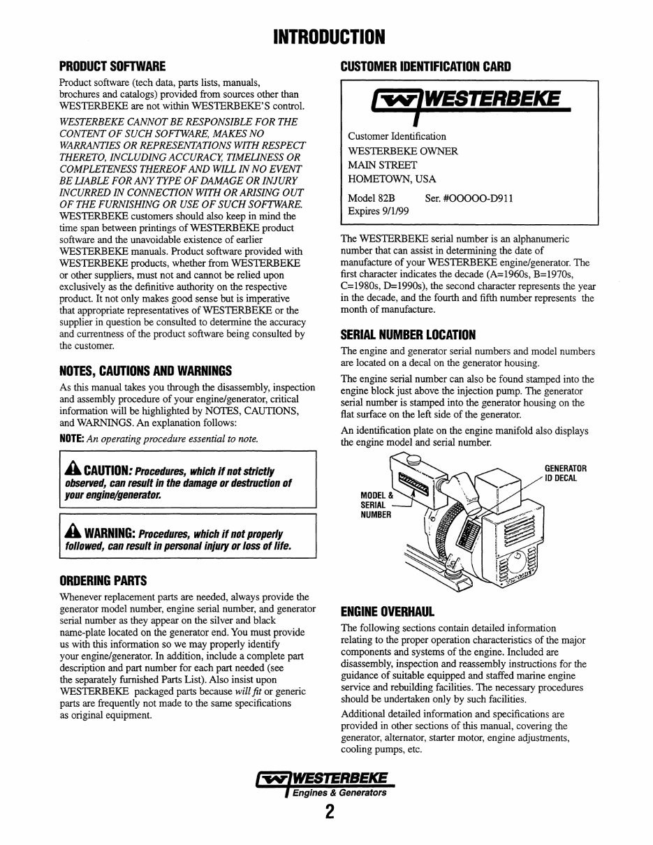
INTRODUCTION PRODUCT SOFTWARE Product software (tech data, parts lists, manuals, brochures and catalogs) provided from sources other than WESTERBEKE are not within WESTERBEKE'S control. WESTERBEKE CANNOT BE RESPONSIBLE FOR THE CONTENT OF SUCH SOFTWARE, MAKES NO WARRANTIES OR REPRESENTATIONS WITH RESPECT THERETO, INCLUDING ACCURACY, TIMEUNESS OR COMPLETENESS THEREOF AND WILL IN NO EVENT BE UABLE FOR ANY TYPE OF DAMAGE OR INJURY INCURRED IN CONNECTION WITH OR ARISING OUT OF THE FURNISHING OR USE OF SUCH SOFTWARE. WESTERBEKE customers should also keep in mind the time span between printings ofWESTERBEKE product software and the unavoidable existence of earlier WESTERBEKE manuals. Product software provided with WESTERBEKE products, whether from WESTERBEKE or other suppliers, must not and cannot be relied upon exclusively as the definitive authority on the respective product. It not only makes good sense but is imperative that appropriate representatives of WESTERBEKE or the supplier in question be consulted to determine the accuracy and currentness of the product software being consulted by the customer. NOTES, CAUTIONS AND WARNINGS As this manual takes you through the disassembly, inspection and assembly procedure of your engine/generator, critical information will be highlighted by NOTES, CAUTIONS, and WARNINGS. An explanation follows: NOTE: An operating procedure essential to note. A CAUTION: Procedures, which if not strictly observed, can result in the damage or destruction of your engine/generator. A WARNING: Procedures, which if not properly followed, can result in personal injury or loss of life. ORDERING PARTS Whenever replacement parts are needed, always provide the generator model number, engine serial number, and generator serial number as they appear on the silver and black name-plate located on the generator end. You must provide us with this information so we may properly identify your engine/generator. In addition, include a complete part description and part number for each part needed (see the separately furnished Parts List). Also insist upon WESTERBEKE packaged parts because will fit or generic parts are frequently not made to the same specifications as original equipment. CUSTOMER IDENTIFICATION CARD / .... 'WESTERBEKE I Customer Identification WESTERBEKE OWNER MAIN STREET HOMETOWN, USA Model82B Expires 9/1/99 Ser. #OOOOO-D911 The WESTERBEKE serial number is an alphanumeric number that can assist in determining the date of manufacture of your WESTERBEKE engine/generator. The first character indicates the decade (A=1960s, B=1970s, C=1980s, D=1990s), the second character represents the year in the decade, and the fourth and fifth number represents the month of manufacture. SERIAL NUMBER LOCATION The engine and generator serial numbers and model numbers are located on a decal on the generator housing. The engine serial number can also be found stamped into the engine block just above the injection pump. The generator serial number is stamped into the generator housing on the flat surface on the left side of the generator. An identification plate on the engine manifold also displays the engine model and serial number. MODEL & SERIAL NUMBER ENGINE OVERHAUL GENERATOR 10 DECAL The following sections contain detailed information relating to the proper operation characteristics of the major components and systems of the engine. Included are disassembly, inspection and reassembly instructions for the guidance of suitable equipped and staffed marine engine service and rebuilding facilities. The necessary procedures should be undertaken only by such facilities. Additional detailed information and specifications are provided in other sections of this manual, covering the generator, alternator, starter motor, engine adjustments, cooling pumps, etc. Engines & Generators 2
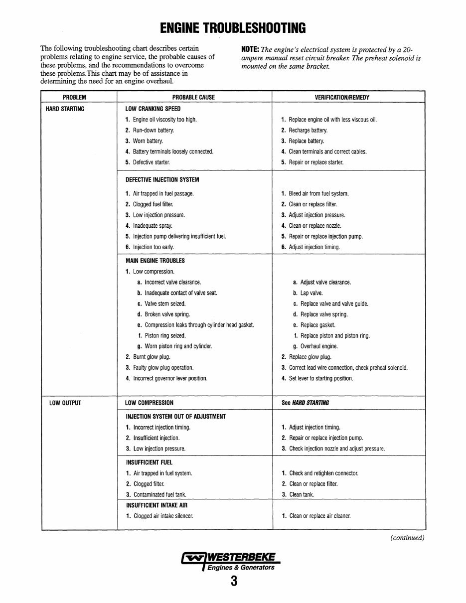
ENGINE TROUBLESHOOTING The following troubleshooting chart describes certain problems relating to engine service, the probable causes of these problems, and the recommendations to overcome these problems.This chart may be of assistance in determining the need for an engine overhaul. PROBLEM PROBABLE CAUSE HARD STARTING LOW CRANKING SPEED 1. Engine oil viscosity too high. 2. Run-down battery. 3. Worn battery. 4. Battery terminals loosely connected. 5. Defective starter. DEFECTIVE INJECTION SYSTEM 1. Air trapped in fuel passage. 2. Clogged fuel filter. 3. Low injection pressure. 4. Inadequate spray. 5. Injection pump delivering insufficient fuel. 6. Injection too early. MAIN ENGINE TROUBLES 1. Low compression. a. Incorrect valve clearance. b. Inadequate contact of valve seat. c. Valve stem seized. d. Broken valve spring. NOTE: The engine's electrical system is protected by a 20- ampere manual reset circuit breaker. The preheat solenoid is mounted on the same bracket. VERIFICATION/REMEDY 1. Replace engine oil with less viscous oil. 2. Recharge battery. 3. Replace battery. 4. Clean terminals and correct cables. 5. Repair or replace starter. 1. Bleed air from fuel system. 2. Clean or replace filter. 3. Adjust injection pressure. 4. Clean or replace nozzle. 5. Repair or replace injection pump. 6. Adjust injection timing. a. Adjust valve clearance. b. Lap valve. c. Replace valve and valve guide. d. Replace valve spring. e. Compression leaks through cylinder head gasket. e. Replace gasket. /. Piston ring seized. /. Replace piston and piston ring. g. Worn piston ring and cylinder. g. Overhaul engine. 2. Burnt glow plug. 2. Replace glow plug. 3. Faulty glow plug operation. 3. Correct lead wire connection, check preheat solenoid. 4. Incorrect governor lever position. 4. Set lever to starting position. LOW OUTPUT LOW COMPRESSION See HARD STARTING INJECTION SYSTEM OUT OF ADJUSTMENT 1. Incorrect injection timing. 1. Adjust injection timing. 2. Insufficient injection. 2. Repair or replace injection pump. 3. Low injection pressure. 3. Check injection nozzle and adjust pressure. INSUFFICIENT FUEL 1. Air trapped in fuel system. 1. Check and retighten connector. 2. Clogged filter. 2. Clean or replace filter. 3. Contaminated fuel tank. 3. Clean tank. INSUFFICIENT INTAKE AIR 1. Clogged air intake silencer. 1. Clean or replace air cleaner. (continued) Engines & Generators 3
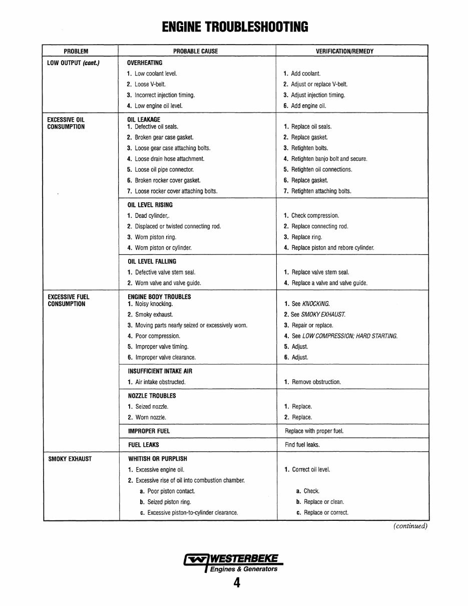
ENGINE TROUBLESHOOTING PROBLEM PROBABLE CAUSE VERIFICATION/REMEDY LOW OUTPUT (cont.) OVERHEATING 1. Low coolant level. 1. Add coolant. 2. Loose V-belt. 2. Adjust or replace V-belt. 3. Incorrect injection timing. 3. Adjust injection timing. 4. Low engine oillevel. 6. Add engine oil. EXCESSIVE OIL OIL LEAKAGE CONSUMPTION 1. Defective oil seals. 1. Replace oil seals. 2. Broken gear case gasket. 2. Replace gasket. 3. Loose gear case attaching bolts. 3. Retighten bolts. 4. Loose drain hose attachment. 4. Retighten banjo bolt and secure. 5. Loose oil pipe connector. 5. Retighten oil connections. 6. Broken rocker cover gasket. 6. Replace gasket. 7. Loose rocker cover attaching bolts. 7. Retighten attaching bolts. OIL LEVEL RISING 1. Dead cylinder,. 1. Check compression. 2. Displaced or twisted connecting rod. 2. Replace connecting rod. 3. Worn piston ring. 3. Replace ring. 4. Worn piston or cylinder. 4. Replace piston and rebore cylinder. OIL LEVEL FALLING 1. Defective valve stem seal. 1. Replace valve stem seal. 2. Worn valve and valve guide. 4. Replace a valve and valve guide. EXCESSIVE FUEL ENGINE BODY TROUBLES CONSUMPTION 1. Noisy knocking. 1. See KNOCKING. 2. Smoky exhaust. 2. See SMOKY EXHAUST. 3. Moving parts nearly seized or excessively worn. 3. Repair or replace. 4. Poor compression. 4. See LOW COMPRESSION; HARD STARTING. 5. Improper valve timing. 5. Adjust. 6. Improper valve clearance. 6. Adjust. INSUFFICIENT INTAKE AIR 1. Air intake obstructed. 1. Remove obstruction. NOZZLE TROUBLES 1. Seized nozzle. 1. Replace. 2. Worn nozzle. 2. Replace. IMPROPER FUEL Replace with proper fuel. FUEL LEAKS Find fuel leaks. SMOKY EXHAUST WHITISH OR PURPLISH 1. Excessive engine oil. 1. Correct oil level. 2. Excessive rise of oil into combustion chamber. a. Poor piston contact. a. Check. b. Seized piston ring. b. Replace or clean. c. Excessive piston-to-cylinder clearance. c. Replace or correct. (continued) Engines & Generators 4
You're Reading a Preview
What's Included?
Lifetime Access
Fast Download Speeds
Online & Offline Access
Access PDF Contents & Bookmarks
Full Search Facility
Print one or all pages of your manual
$31.99
WESTERBEKE 82B FOUR Marine Diesel Engine Workshop Manual
This service repair manual is for the Westerbeke 82B Four Marine Diesel Engine, a 2.98L 4-cylinder, 4-stroke, water-cooled, diesel engine.
Specifications
Engine Overhaul
Engine Disassembly
Engine Assembly
Cylinderhead-Valves
Gearcase & Oil Pump
Timing Gears
Camshaft-Crankshaft
Piston-Connecting Rod
Fuel System
Governor System
Glow Plug System
Cooling System
Starter System
Alternator System
Marine Transmission
Tightening Torque
Troubleshooting
This manual is compatible with all Windows and Mac versions. It is available in Adobe Acrobat Reader format and has a file size of 10 MB.
Presented in electronic format, this manual allows you to print the necessary pages and dispose of them after use. It contains detailed illustrations, step-by-step written instructions, and necessary diagrams or pictures. This manual is suitable for both do-it-yourself enthusiasts and experienced mechanics, serving as a valuable source for repair and service information. By using this repair manual, you can effectively maintain your machine at a low cost. The level of detail and illustrations provided in this manual effectively guide the reader through each service, repair, and maintenance procedure.
Reviews
Q&A
Recently Viewed
5,521,897Happy Clients
2,594,462eManuals
1,120,453Trusted Sellers
15Years in Business
Price:
Actual Price:
WESTERBEKE 82B FOUR Marine Diesel Engine Workshop Manual