

Wartsila 8L26 Product Manual
What's Included?
Fast Download Speeds
Online & Offline Access
Access PDF Contents & Bookmarks
Full Search Facility
Print one or all pages of your manual

WÄRTSILÄ 26
PRODUCT GUIDE


Introduction
This Product Guide provides data and system proposals for the early design phase of marine engine install-
ations. For contracted projects specific instructions for planning the installation are always delivered. Any
data and information herein is subject to revision without notice. This 1/2013 issue replaces all previous
issues of the Wärtsilä 26 Project Guides.
Updates Published Issue
Updates throughout the product guide 20.11.2013 1/2013
Attached drawings updated (Online version). xx.01.2010 2/2009
Technical data added for IMO Tier 2 engines, Compact Silencer System added,
Chapter Exhaust Emissions updated and several other minor updates
26.11.2009 1/2009
Wärtsilä, Ship Power Technology
Vaasa, November 2013
THIS PUBLICATION IS DESIGNED TO PROVIDE AS ACCURATE AND AUTHORITATIVE INFORMATION REGARDING THE SUBJECTS COVERED AS
WAS AVAILABLE AT THE TIME OF WRITING. HOWEVER, THE PUBLICATION DEALS WITH COMPLICATED TECHNICAL MATTERS AND THE DESIGN
OF THE SUBJECT AND PRODUCTS IS SUBJECT TO REGULAR IMPROVEMENTS, MODIFICATIONS AND CHANGES. CONSEQUENTLY, THE PUB-
LISHER AND COPYRIGHT OWNER OF THIS PUBLICATION CANNOT TAKE ANY RESPONSIBILITY OR LIABILITY FOR ANY ERRORS OR OMISSIONS
IN THIS PUBLICATION OR FOR DISCREPANCIES ARISING FROM THE FEATURES OF ANY ACTUAL ITEM IN THE RESPECTIVE PRODUCT BEING
DIFFERENT FROM THOSE SHOWN IN THIS PUBLICATION. THE PUBLISHER AND COPYRIGHT OWNER SHALL NOT BE LIABLE UNDER ANY CIR-
CUMSTANCES, FOR ANY CONSEQUENTIAL, SPECIAL, CONTINGENT, OR INCIDENTAL DAMAGES OR INJURY, FINANCIAL OR OTHERWISE,
SUFFERED BY ANY PART ARISING OUT OF, CONNECTED WITH, OR RESULTING FROM THE USE OF THIS PUBLICATION OR THE INFORMATION
CONTAINED THEREIN.
COPYRIGHT © 2013 BY WÄRTSILÄ FINLAND OY
ALL RIGHTS RESERVED. NO PART OF THIS PUBLICATION MAY BE REPRODUCED OR COPIED IN ANY FORM OR BY ANY MEANS, WITHOUT PRIOR
WRITTEN PERMISSION OF THE COPYRIGHT OWNER.
Product Guide W26 - 1/2013 iii
Wärtsilä 26 - Product Guide
Introduction

Table of Contents
1 1. Main Data and Outputs .............................................................................................................................
1 1.1 Maximum continuous output ............................................................................................................
2 1.2 Reference conditions ........................................................................................................................
2 1.3 Operation in inclined position ..........................................................................................................
3 1.4 Dimensions and weights ..................................................................................................................
6 2. Operating Ranges .....................................................................................................................................
6 2.1 Engine operating range ....................................................................................................................
8 2.2 Loading capacity ..............................................................................................................................
10 2.3 Operation at low load and idling .......................................................................................................
10 2.4 Low air temperature ........................................................................................................................
11 3. Technical Data ...........................................................................................................................................
11 3.1 Wärtsilä 6L26 ...................................................................................................................................
13 3.2 Wärtsilä 8L26 ...................................................................................................................................
15 3.3 Wärtsilä 9L26 ...................................................................................................................................
17 3.4 Wärtsilä 12V26 .................................................................................................................................
19 3.5 Wärtsilä 16V26 .................................................................................................................................
21 4. Description of the Engine .........................................................................................................................
21 4.1 Definitions .........................................................................................................................................
21 4.2 Main engine components .................................................................................................................
25 4.3 Cross section of the engine ..............................................................................................................
27 4.4 Overhaul intervals and expected life times .......................................................................................
27 4.5 Engine storage .................................................................................................................................
28 5. Piping Design, Treatment and Installation ..............................................................................................
28 5.1 Pipe dimensions ...............................................................................................................................
29 5.2 Trace heating ....................................................................................................................................
29 5.3 Operating and design pressure ........................................................................................................
30 5.4 Pipe class .........................................................................................................................................
30 5.5 Insulation ..........................................................................................................................................
30 5.6 Local gauges ....................................................................................................................................
30 5.7 Cleaning procedures ........................................................................................................................
31 5.8 Flexible pipe connections .................................................................................................................
32 5.9 Clamping of pipes .............................................................................................................................
34 6. Fuel Oil System .........................................................................................................................................
34 6.1 Acceptable fuel characteristics .........................................................................................................
37 6.2 Internal fuel oil system .....................................................................................................................
40 6.3 External fuel oil system ....................................................................................................................
57 7. Lubricating Oil System .............................................................................................................................
57 7.1 Lubricating oil requirements .............................................................................................................
58 7.2 Internal lubricating oil system ...........................................................................................................
62 7.3 External lubricating oil system ..........................................................................................................
67 7.4 Crankcase ventilation system ...........................................................................................................
68 7.5 Flushing instructions ........................................................................................................................
69 8. Compressed Air System ...........................................................................................................................
69 8.1 Instrument air quality ........................................................................................................................
69 8.2 Internal compressed air system .......................................................................................................
72 8.3 External compressed air system ......................................................................................................
75 9. Cooling Water System ..............................................................................................................................
75 9.1 Water quality ...................................................................................................................................
76 9.2 Internal cooling water system ...........................................................................................................
82 9.3 External cooling water system ..........................................................................................................
iv Product Guide W26 - 1/2013
Wärtsilä 26 - Product Guide
Table of Contents

91 10. Combustion Air System ...........................................................................................................................
91 10.1 Engine room ventilation ....................................................................................................................
92 10.2 Combustion air system design .........................................................................................................
95 11. Exhaust Gas System .................................................................................................................................
95 11.1 Internal exhaust gas system .............................................................................................................
99 11.2 Exhaust gas outlet ............................................................................................................................
100 11.3 External exhaust gas system ...........................................................................................................
106 12. Turbocharger Cleaning .............................................................................................................................
106 12.1 Turbine cleaning system ...................................................................................................................
106 12.2 Compressor cleaning system ...........................................................................................................
107 13. Exhaust Emissions ...................................................................................................................................
107 13.1 Diesel engine exhaust components .................................................................................................
108 13.2 Marine exhaust emissions legislation ...............................................................................................
112 13.3 Methods to reduce exhaust emissions .............................................................................................
113 14. Automation System ..................................................................................................................................
113 14.1 UNIC C2 ...........................................................................................................................................
118 14.2 Functions ..........................................................................................................................................
119 14.3 Alarm and monitoring signals ...........................................................................................................
121 14.4 Electrical consumers ........................................................................................................................
123 15. Foundation .................................................................................................................................................
123 15.1 Steel structure design ......................................................................................................................
123 15.2 Mounting of main engines ................................................................................................................
131 15.3 Mounting of generating sets .............................................................................................................
133 15.4 Flexible pipe connections .................................................................................................................
134 16. Vibration and Noise ..................................................................................................................................
134 16.1 External forces and couples .............................................................................................................
135 16.2 Torque variations ..............................................................................................................................
135 16.3 Mass moments of inertia ..................................................................................................................
136 16.4 Air borne noise .................................................................................................................................
137 16.5 Exhaust noise ...................................................................................................................................
138 17. Power Transmission .................................................................................................................................
138 17.1 Flexible coupling ...............................................................................................................................
139 17.2 Clutch ...............................................................................................................................................
139 17.3 Shaft locking device ..........................................................................................................................
140 17.4 Power-take-off from the free end ......................................................................................................
142 17.5 Input data for torsional vibration calculations ...................................................................................
143 17.6 Turning gear .....................................................................................................................................
144 18. Engine Room Layout ................................................................................................................................
144 18.1 Crankshaft distances ........................................................................................................................
147 18.2 Space requirements for maintenance ..............................................................................................
147 18.3 Transportation and storage of spare parts and tools ........................................................................
147 18.4 Required deck area for service work ................................................................................................
152 19. Transport Dimensions and Weights ........................................................................................................
152 19.1 Lifting of main engines .....................................................................................................................
154 19.2 Lifting of generating sets ..................................................................................................................
155 19.3 Engine components ..........................................................................................................................
157 20. Product Guide Attachments .....................................................................................................................
158 21. ANNEX ........................................................................................................................................................
158 21.1 Unit conversion tables ......................................................................................................................
160 21.2 Collection of drawing symbols used in drawings ..............................................................................
Product Guide W26 - 1/2013 v
Wärtsilä 26 - Product Guide
Table of Contents

vi Product Guide W26 - 1/2013
Wärtsilä 26 - Product Guide
This page intentionally left blank

1. Main Data and Outputs
The Wärtsilä 26 is a 4-stroke, non-reversible, turbocharged and intercooled diesel engine with direct fuel
injection.
260 mm Cylinder bore ..........................................
320 mm Stroke .....................................................
17,0 l/cyl Piston displacement ..............................
2 inlet valves and 2 exhaust valves Number of valves ...................................
6, 8 and 9 in-line; 12 and 16 in V-form Cylinder configuration ............................
55° V angle ...................................................
clockwise, counter-clockwise on request Direction of rotation ................................
900, 1000 rpm Speed .....................................................
9.6, 10.7 m/s Mean piston speed ................................
1.1 Maximum continuous output
Table 1.1 Rating table for Wärtsilä 26
Generating sets Main engines Cylinder con-
figuration
1000 rpm 900 rpm 1000 rpm 900 rpm
[kWe] [KVA] [kWe] [KVA] [kW] [kW]
1969 2461 1882 2352 2040 1950 6L26
2625 3281 2509 3136 2720 2600 8L26
2953 3691 2823 3528 3060 2925 9L26
3937 4922 3764 4704 4080 3900 12V26
5250 6562 5018 6273 5440 5200 16V26
The generator outputs are calculated for an efficiency of 96.5% and a power factor of 0.8. The maximum
fuel rack position is mechanically limited to 110% of the continuous output for engines driving generators.
The mean effective pressure p
e
can be calculated as follows:
where:
mean effective pressure [bar] P
e
=
output per cylinder [kW] P=
engine speed [rpm] n=
Cylinder diameter [mm] D=
length of piston stroke [mm] L=
operating cycle (4) c=
Product Guide W26 - 1/2013 1
Wärtsilä 26 - Product Guide
1. Main Data and Outputs

1.2 Reference conditions
The output is available up to a charge air coolant temperature of max. 38°C and an air temperature of max.
45°C. For higher temperatures, the output has to be reduced according to the formula stated in ISO 3046-
1:2002 (E).
The specific fuel oil consumption is stated in the chapter Technical data. The stated specific fuel oil con-
sumption applies to engines without engine driven pumps, operating in ambient conditions according to
ISO 15550:2002 (E). The ISO standard reference conditions are:
100 kPa total barometric pressure
25°C air temperature
30% relative humidity
25°C charge air coolant temperature
Correction factors for the fuel oil consumption in other ambient conditions are given in standard ISO 3046-
1:2002.
1.3 Operation in inclined position
Max. inclination angles at which the engine will operate satisfactorily.
15° Transverse inclination, permanent (list) .........
22.5° Transverse inclination, momentary (roll) ........
5° Longitudinal inclination, permanent (trim) ......
7.5° Longitudinal inclination, momentary (pitch) ....
Larger angles are possible with special arrangements.
2 Product Guide W26 - 1/2013
Wärtsilä 26 - Product Guide
1. Main Data and Outputs

1.4 Dimensions and weights
1.4.1 Main engines
Figure 1.1 In-line engines (DAAE034755b)
G F
dry
F
wet
E D C C* B B* A A* Engine
2866 818 950 400 2430 2020 1960 1833 1882 4130 4387 W 6L26
3646 818 950 400 2430 2107 2010 1868 2023 5059 5302 W 8L26
4036 818 950 400 2430 2107 2016 1868 2023 5449 5691 W 9L26
Weight
N N* M M* K I H Engine
wet sump dry sump
17.2 17.0 904 669 1171 1103 1420 920 186 W 6L26
21.9 21.6 1054 794 1258 1167 1420 920 186 W 8L26
23.6 23.3 1054 794 1258 1167 1420 920 186 W 9L26
Dry sump Wet sump Engine
Gz Gy Gx Gz * Gy * Gx * Gz Gy Gx Gz * Gy * Gx *
458 90 1300 458 90 1551 450 90 1300 450 90 1551 W 6L26
465 78 1704 465 78 2002 457 78 1704 457 78 2002 W 8L26
462 74 1921 462 74 2204 454 74 1921 454 74 2204 W 9L26
* Turbocharger at flywheel end.
All dimensions in mm. Weight in metric tons with liquids (wet sump) but without flywheel.
Product Guide W26 - 1/2013 3
Wärtsilä 26 - Product Guide
1. Main Data and Outputs
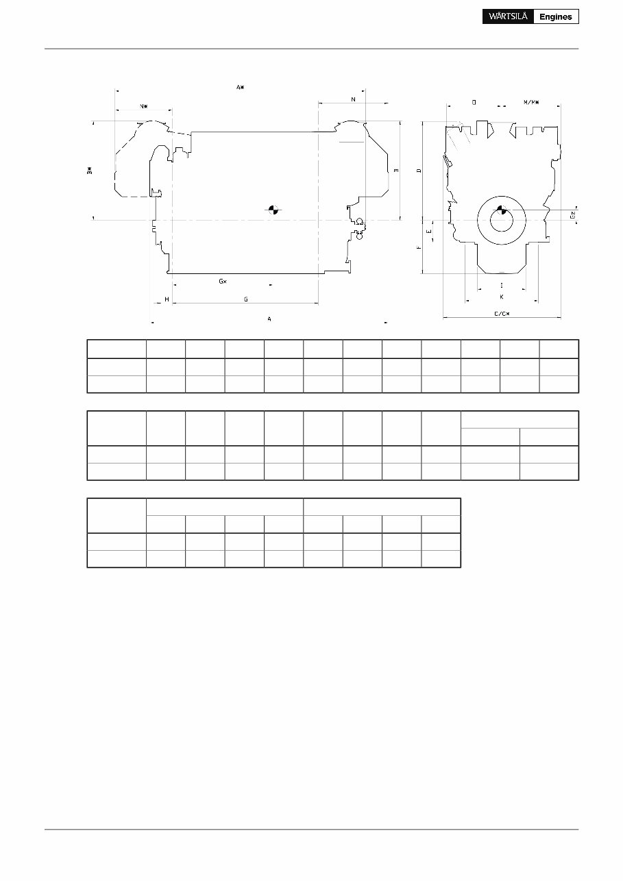
Figure 1.2 V-engines (DAAE034757b)
G F
dry
F
wet
E D C C* B B* A A* Engine
3035 800 1110 460 2060 2602 2552 2034 2034 5314 5442 W 12V26
3875 800 1110 460 2060 2763 2489 2190 2151 6025 6223 W 16V26
Weight
O N N* M M* K I H Engine
wet sump dry sump
29.0 28.7 1148 1698 1433 1238 1364 1530 1010 235 W 12V26
37.9 36.1 1160 1626 1363 1248 1248 1530 1010 235 W 16V26
Dry sump Wet sump Engine
Gz Gx Gz * Gx * Gz Gx Gz * Gx *
470 1811 470 1224 413 1811 413 1224 W 12V26
568 2258 568 1852 548 2258 548 1852 W 16V26
* Turbocharger at flywheel end.
All dimensions in mm. Weight in metric tons with liquids (wet sump) but without flywheel.
4 Product Guide W26 - 1/2013
Wärtsilä 26 - Product Guide
1. Main Data and Outputs
You're Reading a Preview
What's Included?
Fast Download Speeds
Online & Offline Access
Access PDF Contents & Bookmarks
Full Search Facility
Print one or all pages of your manual
$26.99
Viewed 89 Times Today


Secure transaction
What's Included?
Fast Download Speeds
Online & Offline Access
Access PDF Contents & Bookmarks
Full Search Facility
Print one or all pages of your manual
$26.99
- Discover the Wartsila 8L26 Product Manual, your comprehensive guide to the functionalities and maintenance of the Wartsila 8L26 engine models.
- This manual covers all the important details and specifications you need to know about the 8L26 engine.
- Whether you own the Wartsila 8L26A, 8L26B, or 8L26C model, this product manual is the perfect companion to help you optimize the performance and longevity of your engine.
- With detailed step-by-step instructions and illustrations, you will be able to easily navigate through the operational procedures, servicing requirements, troubleshooting, and more.
- This product manual is a must-have for all Wartsila 8L26 owners who want to ensure the smooth operation and maintenance of their engines.


