Number 23 Printed in U.S.A. 90-861326--1 MARCH 1999 1999, Mercury Marine MARINE ENGINES SERVICE MANUAL GM V8 454 cid (7.4L) / 502 cid (8.2L) Book 1 of 2 Sections 1 thru 4
90-861326--1 MARCH 1999 Page i Notice Throughout this publication, “Dangers”, “Warnings” and “Cautions” (accompanied by the In- ternational HAZARD Symbol ) are used to alert the mechanic to special instructions con- cerning a particular service or operation that may be hazardous if performed incorrectly or carelessly. OBSERVE THEM CAREFULLY! These “Safety Alerts” alone cannot eliminate the hazards that they signal. Strict compliance to these special instructions when performing the service, plus “Common Sense” operation, are major accident prevention measures. DANGER DANGER - Immediate hazards which WILL result in severe personal injury or death. WARNING WARNING - Hazards or unsafe practices which COULD result in severe personal in- jury or death. CAUTION Hazards or unsafe practices which could result in minor personal injury or product or property damage. Notice to Users of This Manual This service manual has been written and published by the Service Department of Mercury Marine to aid our dealers’ mechanics and company service personnel when servicing the products described herein. It is assumed that these personnel are familiar with the servicing procedures of these prod- ucts, or like or similar products manufactured and marketed by Mercury Marine, that they have been trained in the recommended servicing procedures of these products which in- cludes the use of mechanics’ common hand tools and the special Mercury Marine or recom- mended tools from other suppliers. We could not possibly know of and advise the service trade of all conceivable procedures by which a service might be performed and of the possible hazards and/or results of each method. We have not undertaken any such wide evaluation. Therefore, anyone who uses a service procedure and/or tool, which is not recommended by the manufacturer, first must completely satisfy himself that neither his nor the products safety will be endangered by the service procedure selected. All information, illustrations and specifications contained in this manual are based on the latest product information available at the time of publication. As required, revisions to this manual will be sent to all dealers contracted by us to sell and/or service these products. It should be kept in mind, while working on the product, that the electrical system and ignition system are capable of violent and damaging short circuits or severe electrical shocks. When performing any work where electrical terminals could possibly be grounded or touched by the mechanic, the battery cables should be disconnected at the battery. Any time the intake or exhaust openings are exposed during service they should be covered to protect against accidental entrance of foreign material which could enter the cylinders and cause extensive internal damage when the engine is started.
Page ii 90-861326--1 MARCH 1999 It is important to note, during any maintenance procedure replacement fasteners must have the same measurements and strength as those removed. Numbers on the heads of the met- ric bolts and on the surfaces of metric nuts indicate their strength. American bolts use radial lines for this purpose, while most American nuts do not have strength markings. Mis- matched or incorrect fasteners can result in damage or malfunction, or possibly personal injury. Therefore, fasteners removed should be saved for reuse in the same locations when- ever possible. Where the fasteners are not satisfactory for re-use, care should be taken to select a replacement that matches the original. We reserve the right to make changes to this manual without prior notification. Refer to dealer service bulletins for other pertinent information concerning the products de- scribed in this manual. Engine Mechanical Components Many of the engine mechanical components are designed for marine applications. Unlike automotive engines, marine engines are subjected to extended periods of heavy load and wide-open-throttle operation and, therefore, require heavy-duty components. Special marine engine parts have design and manufacturing specifications which are required to provide long life and dependable performance. Marine engine parts also must be able to resist the corrosive action of salt or brackish water that will rust or corrode standard automo- tive parts within a short period of time. Failure to use recommended Quicksilver service replacement parts can result in poor en- gine performance and/or durability, rapid corrosion of parts subjected to salt water and possibly complete failure of the engine. Use of parts other than recommended service replacement parts, will void the warranty on those parts which are damaged as a result of the use of other than recommended replace- ment parts. Replacement Parts WARNING Electrical, ignition and fuel system components on MerCruiser Engines and Stern Drives are designed and manufactured to comply with U.S. Coast Guard Rules and Regulations to minimize risks of fire or explosion. Use of replacement electrical, ignition or fuel system components, which do not comply to these rules and regulations, could result in a fire or explosion hazard and should be avoided. When servicing the electrical, ignition and fuel systems, it is extremely important that all components are properly installed and tightened. If not, any electrical or ig- nition component opening would permit sparks to ignite fuel vapors from fuel sys- tem leaks, if they existed.
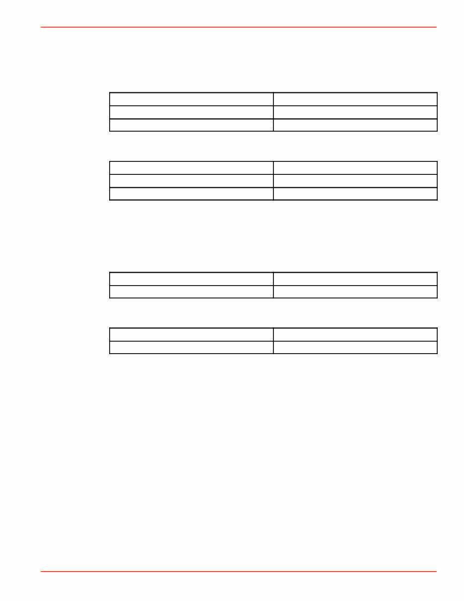
90-861326--1 MARCH 1999 Page iii Models Covered in This Manual Gen. VI Engines Sterndrive (MCM) Model Serial Number MCM 454 Mag MPI 0L010029 & Up MCM 502 Mag MPI 0L017000 & Up Inboard (MIE) Model Serial Number MIE 454 Mag MPI Horizon 0L002200 & Up MIE 8.2L MPI 0L002450 & Up L-29 Engines Sterndrive (MCM) Model Serial Number MCM 7.4L MPI 0L010003 & Up Inboard (MIE) Model Serial Number MIE 7.4L MPI 0L002006 & Up
Page iv 90-861326--1 MARCH 1999 THIS PAGE IS INTENTIONALLY BLANK
1 2 3 4 5 6 7 8 Important Information Removal And Installation Engine Electrical System Fuel System Cooling System Exhaust System Drives 9 Power Steering 90-861326--1 MARCH 1999 Page v Service Manual Outline Section 1 - Important Information A - General Information B - Maintenance C - Troubleshooting Section 2 - Removal and Installation A - MCM Models - Bravo and Blackhawk Drives B - MCM Models - Bravo and Blackhawk Drives with Driveshaft Extension C - MIE Models - Velvet Drive Transmission D - MIE Models - Hurth Transmission Section 3 - Engine A - 454 cid (7.4L) / 502 cid (8.2L) Section 4 - Electrical System A - Starting System B - Ignition System C - Charging System D - Instrumentation E - Wiring Diagrams Section 5 - Fuel System A - Fuel Delivery System for Electronic Fuel Injection B - Multi-Port Fuel Injection Descriptions and System Operation C - Multi-Port Fuel Injection Disassembly and Reassembly D - Fuel Injection System Troubleshooting E - General System Diagnostics F - Trouble Code Diagnostics - 454/502 Mag MPI & 8.2L MPI G - Trouble Code Diagnostics - 7.4L MPI Section 6 - Cooling System A - Seawater Cooled Models B - Closed Cooled (Fresh Water) Models Section 7 - Exhaust System A - General B - Manifolds and Elbows C - Risers D - Collectors Section 8 - Drives A - Velvet Drive In-Line Transmission B - Velvet Drive 5000A Down Angle Transmission C - Velvet Drive 5000V V-Drive Transmission D - Hurth V-Drive Transmission E - Walter V-Drive Transmission F - Drive Shaft / Propeller Shaft Models Section 9 - Power Steering A - Pump
Page vi 90-861326--1 MARCH 1999 THIS PAGE IS INTENTIONALLY BLANK
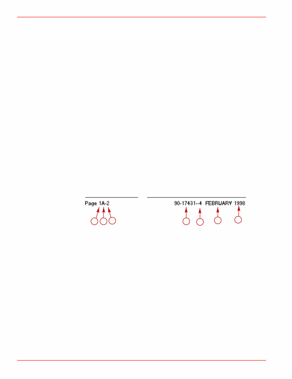
GENERAL INFORMATION SERVICE MANUAL NUMBER 23 Page 1A-2 90-861326--1 MARCH 1999 Introduction This comprehensive overhaul and repair manual is designed as a service guide for the models previously listed. It provides specific information, including procedures for disassembly, inspection, assembly and adjustment to enable dealers and service mechanics to repair and tune these engines. Before attempting repairs or tune-up, it is suggested that the procedure first be read through to gain knowledge of the methods and tools used and the cautions and warnings required for safety. How to Use This Manual This manual is divided into sections which represent major components and systems. Some sections are further divided into parts which more fully describe the component. Sections and section parts are listed on the “Service Manual Outline” page following “V-8 Models Covered in This Manual” page. Page Numbering Two number groups appear at the bottom of each page. Following is an example and description. a b c d e f g a- Section Number b- Section Part c- Page Number d- Manual Number e- Revision No. 4 f- Month Printed g- Year Printed
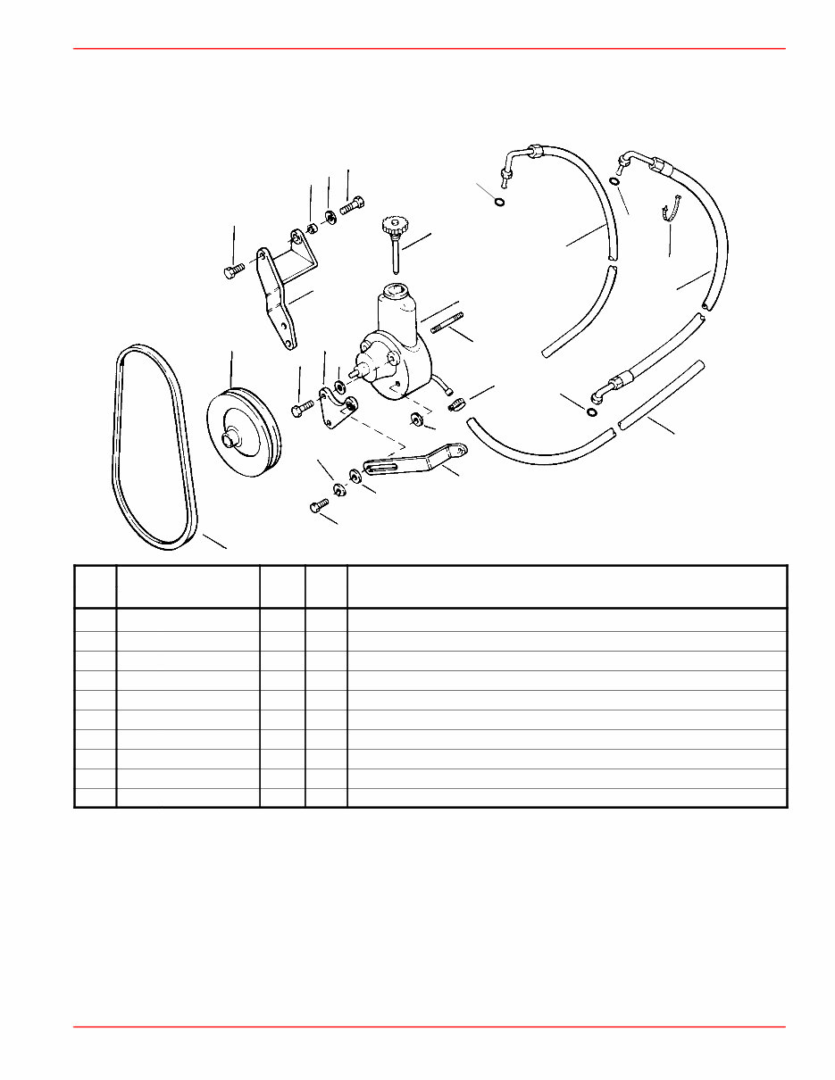
GENERAL INFORMATION SERVICE MANUAL NUMBER 23 90-861326--1 MARCH 1999 Page 1A-3 How to Read a Parts Manual POWER STEERING PUMP ASSEMBLY 1 2 3 4 5 6 7 8 9 10 REF. REF . NO. PART NO. SYM. QTY. DESCRIPTION 1 90507A12 1 PUMP ASSEMBLY-Power Steering 2 36- 95805 1 CAP 3 73873A1 1 PULLEY 4 16- 41877 1 STUD 5 57- 65607T 1 V-BELT 6 32- 806684 1 HOSE-Pressure (FITTINGS ON BOTH ENDS) 7 25- 89879 1 O-RING 8 25- 806232 1 O-RING 9 13- 35048 1 LOCKWASHER (3/8 in.) 10 61990 1 CABLE TIE REF. NO. : Number shown next to part on exploded view PART NO. : Mercury Part Number for ordering. If NSS (not sold separately) sometimes GM part number will be given in description column. QTY. : The quantity that must be ordered. DESCRIPTION : Description of part, what parts are included with a part (all indented items come with the main item above the indented parts), serial number information, and special information.
The Mercury Mercruiser 7.4L (454 CID), 8.2L (502 CID) GM V8 Marine Engines OEM Service & Repair Manual delivers comprehensive technical documentation for these legendary big-block powerplants in both sterndrive (MCM) and inboard (MIE) configurations. This digital resource contains detailed specifications, troubleshooting flowcharts, and repair procedures covering critical systems—from multi-port fuel injection to cooling systems specifically designed for marine environments.
These marine-adapted big blocks share DNA with their automotive counterparts but feature specialized components engineered specifically for the harsh saltwater environment. Whether you're a certified marine technician or a hands-on boat owner, this manual reveals crucial insights like the specific torque sequence for exhaust manifolds that prevents those expensive water intrusion problems.
This manual includes key sections such as:
Section 1 - Important Information
A - General Information
B - Maintenance
C - Troubleshooting
Section 2 - Removal and Installation
A - MCM Models - Bravo and Blackhawk Drives
B - MCM Models - Bravo and Blackhawk Drives with Driveshaft Extension
C - MIE Models - Velvet Drive Transmission
D - MIE Models - Hurth Transmission
Section 3 - Engine
A - 454 cid (7.4L) / 502 cid (8.2L)
Section 4 - Electrical System
A - Starting System
B - Ignition System
C - Charging System
D - Instrumentation
E - Wiring Diagrams
Section 5 - Fuel System
A - Fuel Delivery System for Electronic Fuel Injection
B - Multi-Port Fuel Injection Descriptions and System Operation
C - Multi-Port Fuel Injection Disassembly and Reassembly
Leave the dockside guesswork behind. With detailed procedures for both closed and raw water cooling systems, Velvet Drive and Hurth transmission service, and specialized marine electrical components, this resource helps professional technicians work efficiently while giving boat owners the confidence to handle seasonal maintenance themselves. If you're seeking to maintain your power system's reliability while developing practical skills that minimize expensive marine service calls during the boating season, this is the perfect manual for you.
Printable: Yes Language: English Compatibility: Pretty much any electronic device, incl. PC & Mac computers, Android and Apple smartphones & tablet, etc. Requirements: Adobe Reader (free)