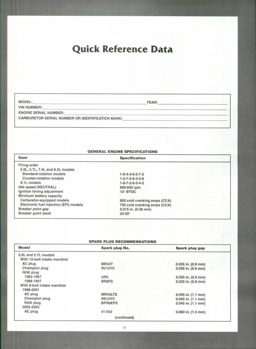
Quick Reference Data MODEL: VIN NUMBER:__ ENGINE SERIAL NUMBER: CARBURETOR SERIAL NUMBER OR IDENTIFICATION MARK: YEAR: GENERAL ENGINE SPECIFICATIONS Item Firing order 5.0L, 5.7L, 7.4L and 8.2L models Standard-rotation models Counter-rotation modeis 8.1 L models Idle speed (NEUTRAL) Ignition timing adjustment Minimum battery capacity Carburetor-equipped modeis Eiectrontc fuei injection (EFI) modeis Breaker point gap Breaker point dweii Specification 1-8-4-3-6-5-7-2 1-2-7-5-6-3-4-8 1-8-7-2-6-5-4-3 600-650 rpm 10" BTDC 650 cold cranking amps (CCA) 750 coid cranking amps (CCA) 0.015 in. (0.38 mm) 24-30° SPARK PLUG RECOMMENDATIONS Modei 5.0L and 5.7L modeis With 12-boit intake manifold AC piug Champion piug NGK piug 1983-1987 1988-1997 With 8-boit intake manifoid 1998-2001 AC piug Champion piug NGK plug 2002-2003 AC plug Spark piug No. MR43T RV12YC UR5 BR6FS MR43LTS RS12YC BPR6EFS 41-932 (continued) Spark plug gap 0.035 in. (0.9 mm) 0.035 in. (0.9 mm) 0.035 in. (0.9 mm) 0.035 in. (0.9 mm) 0.045 in. (1.1 mm) 0.045 in. (1.1 mm) 0.045 in. (1.1 mm) 0.060 in. (1.5 mm) IX
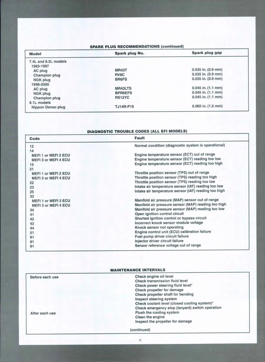
Model 7.4L and 8.2L models 1983-1997 AC plug Champion plug NGK plug 1998-2000 AC plug NGK plug Champion plug 8.1 L modeis Nippon Denso piug SPARK PLUG RECOMMENDATIONS (continued) Spark plug No. MR43T RV8C BR6FS MR43LTS BPR6EFS RS12YC TJ14R-P15 Spark plug gap 0.035 in. (0.9 mm) 0.035 in. (0.9 mm) 0.035 in. (0.9 mm) 0.045 in. (1.1 mm) 0.045 in. (1.1 mm) 0.045 in. (1.1 mm) 0.060 in. (1.5 mm) DIAGNOSTIC TROUBLE CODES (ALL EFI MODELS) Code Fault 12 14 MEF11 or MEFI 2 ECU MEFI 3 or MEFI 4 ECU 15 21 MEF11 or MEFI 2 ECU MEFI 3 or MEFI 4 ECU 22 23 25 33 MEF11 or MEFI 2 ECU MEFt 3 or MEFI 4 ECU 34 41 42 43 44 51 81 81 81 Normal condition (diagnostic system is operationai) Engine temperature sensor (ECT) out of range Engine temperature sensor (ECT) reading too tow Engine temperature sensor (ECT) reading too high Throttle position sensor (TPS) out of range Throttie position sensor (TPS) reading too high Throttle position sensor (TPS) reading too low Intake air temperature sensor (lAT) reading too low Intake air temperature sensor (iAT) reading too high Manlfoid air pressure (MAP) sensor out of range Manifoid air pressure sensor (MAP) reading too high Mantfoid air pressure sensor (MAP) reading too iow Open ignition control circuit Shorted ignition controi or bypass circuit Incorrect knock sensor module voltage Knock sensor not operating Engine control unit (ECU) calibration faiiure Fuei pump driver circuit failure injector driver circuit faiiure Sensor reference voltage out of range MAINTENANCE INTERVALS Before each use After each use Check engine oil levei Check transmission fiuid ievei Check power steering fiuid levei* Check propeiler for damage Check propeiler shaft for bending Inspect steering system Check cooiant level (closed cooling system)* Check emergency stop (lanyard) switch operation Fiush the cooiing system Ciean the engine Inspect the propeller for damage (continued) I
MAINTENANCE INTERVALS (continued) First 20 hours of operation Every 50 hours of operation Every 60 days or 50 hours of operation Once a year or every 100 hours of operation Every two years or 200 hours of operation Change the engine ori and oii fiiter Change the transmission fluid Check power steering fiuid ievel* Ciean or repiace primary fuei fiiter Adjust shift cabie (refer to Chapter Five) Lubricate steering cabie ram* Checi( drive beit tension (refer to Chapter Nine) Tighten hose ciamps and engine mounts Checi( drive beit tension (refer to Chapter Nine) Ciean fiame arrestor Check rubi^er hoses for deterioration Lubricate the steering cabie ram* Change the engine oii and oii fiiter Change the transmission fiuiid Clean or repiace primary fuel filter Check shift cable adjustment (refer to Chapter Five) Check engine aiignment (refer to Chapter Six) Clean PCV vaive* Clean and inspect spark piugs Repiace breaker points and condenser* Replace water pump impelier (refer to Chapter Eight) Change closed cooling system cooiant* *This maintenance item does not apply to ali models. ENGINE OIL CAPACITIES Model Approximate capacity 5.0L and 5.7L models 7.4L and 8.2L modeis 8.1 L modeis 5 qt. (4.7 L) 7 qt. (6.6 L) 9 qt. (8.5 L) TRANSMISSION FLUID CAPACITIES Model Borg-Warner or Regai Beloit 71C (iniine transmission) 72C (V-drive transmission) 5000A series 5000V series ZF Hurth 360 450 630V 630A 800A Walters V-drive RV-36 Approximate capacity 64oz.(1.4L) 3.0 qt. (2.8 L) 2.5 qt. (2.4 L) 3.0 qt. (2.8 L) 47O2.(t.4L) 2.0qt(1.8L) 4.5 qt. (4.3 L) 3.25 qt. (3.1 L) 5.75 qt. (5.4 L) 32 oz. (0.95 L) XI
CHAPTER ONE Chapter Four describes preparing the inboard marine engine for storage. Preparation for operation after the lay-up period is also described in this chapter. Chapter Five describes adjustments for the fuel, igni- tion and shifting systems. Subsequent chapters describe specific systems and pro- vide disassembly, repair and assembly procedures in step-by-step form. Some of the procedures in this manual require special tools. When possible, the tool is illustrated in use. Well-equipped mechanics may substitute similar tools or fabricate a suitable replacement. However, in some cases, the specialized equipment or expertise may make it im- practical for the home mechanic to attempt the procedure. When necessary, such operations are identified in the text with the recommendation to have a dealership or special- ist perform the task. It may be less expensive to have a professional perform these jobs, especially when consid- ering the cost ofthe equipment. This is true regarding ma- chine work for engine rebuilds because machinists spend years perfecting their trade, and even professional mechanics often rely upon their services. WARNINGS, CAUTIONS AND NOTES The terms WARNING, CAUTION, and NOTE have specific meanings in this manual. A WARNING emphasizes areas where personal injury or even death could result from negligence. Mechanical damage may also occur. WARNINGS are to be taken seri- ously. A CAUTION emphasizes areas where equipment dam- age could occur. Disregarding a CAUTION could cause permanent mechanical damage; however, personal injury is unlikely. A NOTE provides additional information to make a step or procedure easier or clearer. Disregarding a NOTE could cause inconvenience or misdiagnosis but would not cause damage or injury. SAFETY Professional mechanics can work for years and never sustain a serious injury. Follow these guidelines and prac- tice common sense to safely service the inboard marine engine. 1. Do not operate the inboard marine engine in an en- closed area. The exhaust gasses contain carbon monox- ide, an odorless, colorless, tasteless and poisonous gas. Carbon monoxide levels build quickly in small enclosed areas and can cause unconsciousness and death in a short time. Make sure to properly ventilate the work area or op- erate the inboard marine engine outside. 2. Never use gasoline or any extremely flammable liquid to clean parts. Refer to Cleaning Parts and Handling Gas- oline Safely in this chapter. 3. Never smoke or use a torch in the vicinity of flamma- ble liquids such as gasoline or cleaning solvent. 4. After removing the engine cover, allow the engine to air out before performing any service work. 5. Use the correct type and size of tools to avoid damag- ing fasteners. 6. Keep tools clean and in good condition. Replace or re- pair worn or damaged equipment. 7. When loosening a tight or stuck fastener, always con- sider what would happen if the wrench should slip. In most cases, it is safer to pull on a wrench or ratchet than it is to push on it. Be careful; protect yourself accordingly. 8. When replacing a fastener, make sure to use one with the same measurements, material and strength as the old one. Refer to Fasteners in this chapter for additional in- formation. 9. Keep the work area clean and uncluttered. Keep all hand and power tools in good condition. Clean grease or oil from tools after using them. Unkept tools are difficult to hold and cause injury. Replace or repair worn or dam- aged tools. Do not leave tools, shop rags or anything that does not belong in the hull. 10. Wear safety goggles during all operations involving drilling, grinding or the use of a cold chisel or anytime eye safety is in question (when debris may spray or scatter). Always wear safety goggles when using solvent or compressed air. 11. Do not carry sharp tools in clothing pockets. 12. Always have an approved fire extinguisher available. Make sure it is rated for gasoline (Class B) and electric (Class C) fires. Read and fully understand the operating instructions for the fire extinguisher before beginning the work. 13- Do not use compressed air to clean clothes, the boat/engine or the work area. Debris might blow into eyes or skin. Never direct compressed air at anyone. Do not al- low children to use or play with any compressed air equip- ment. 14. When using compressed air to dry rotating parts, hold the part so that it cannot rotate. The air jet is capable or ro- tating the parts at extremely high speed. The part can be- come damaged or disintegrate and cause serious injury. Handling Gasoline Safely Gasoline is a volatile flammable liquid and is one ofthe most dangerous items in the shop.
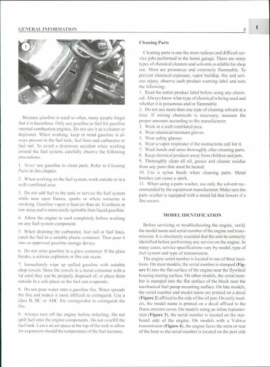
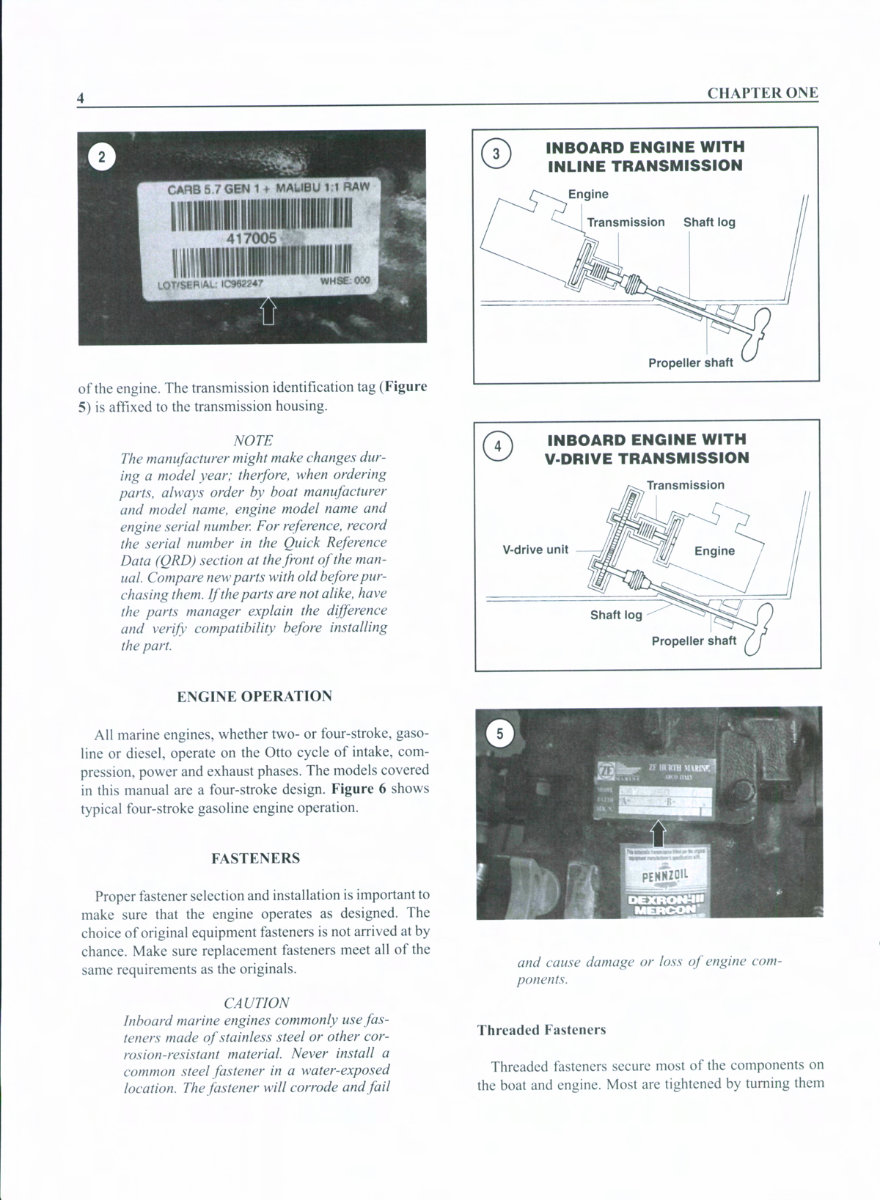
GENERAL INFORMATION Because gasoline is used so often, many people forget that it is hazardous. Only use gasoline as fuel for gasoline internal eombustion engines. Do not use it as a cleaner or degreasen When working, keep in mind gasoline is al- ways present in the fuel tank, fuel lines and carburetor or fuel rail. To avoid a disastrous accident when working around the fuel system, carefully observe the following precautions. 1. Never use gasoline to clean parts. Refer to Cleaning Parts in this ehapter. 2. When working on the fuel system, work outside or in a well-ventilated area. 3. Do not add fuel to the tank or serviee the fuel system while near open flames, sparks or where someone is smoking. Gasoline vapor is heavier than air. It collects in low areas and is more easily ignitable than liquid gasoline. 4. Allow the engine to cool completely before working on any fuel system component. 5. When draining the earburetor, fuel rail or fuel lines, catch the fuel in a suitable plastie container. Then pour it into an approved gasoline storage deviee. 6. Do not store gasoline in a glass container. If the glass breaks, a serious explosion or fire can occur. 7. Immediately wipe up spilled gasoline with suitable shop towels. Store the towels in a metal container with a lid until they ean be properly disposed of, or place them outside in a safe place so the fuel can evaporate. 8. Do not pour water onto a gasoline fire. Water spreads the fire and makes it more difficult to extinguish. Use a class B, BC or ABC fire extinguisher to extinguish the fire. '). Always turn off the engine before refueling. Do not spill fuel onto the engine components. Do not overfill the fuel tank. Leave an air space at the top of the tank to allow for expansion should the temperature of the fuel increase. Cleaning Parts Cleaning parts is one the more tedious and difficult ser- vice jobs performed in the home garage. There are many types of ehemical cleaners and solvents available for shop use. Most are poisonous and extremely flammable. To prevent ehemical exposure, vapor buildup, fire and seri- ous injury, observe each product warning label and note the following: 1. Read the entire product label before using any ehemi- eal. Always know what type of ehemieal is being used and whether it is poisonous and/or flammable. 2. Do not use more than one type of cleaning solvent at a time. If mixing chemicals is necessary, measure the proper amounts according to the manufacturer. 3. Work in a well-ventilated area. 4. Wear chemical-resistant gloves. 5. Wear safety glasses. 6. Wear a vapor respirator if the instructions call for it. 7. Wash hands and arms thoroughly after cleaning parts. 8. Keep chemical products away from children and pets. 9. Thoroughly clean all oil, grease and cleaner residue from any parts that must be heated. 10. Use a nylon brush when cleaning parts. Metal brushes can cause a spark. 11. When using a parts washer, use only the solvent rec- ommended by the equipment manufacturer. Make sure the parts washer is equipped with a metal lid that lowers if a fire oeeurs. MODEL IDENTIFICATION Before servieing or troubleshooting the engine, verify the model name and serial number of the engine and trans- mission. It is absolutely essential that the unit be correctly identified before performing any service on the engine. In many cases, service speeifications vary by model, type of fuel system and type of transmission. The engine serial number is located in one of three loca- tions. On most models, the serial number is stamped (Fig- ure 1) into the fiat surfaee of the engine near the flywheel housing mating surfaee. On other models, the serial num- ber is stamped into the fiat surfaee of the block near the mechanical fuel pump mounting surface. On late models, the serial number and model name are printed on a deeal (Figure 2) affixed to the side of the oil pan. On early mod- els, the model name is printed on a deeal affixed to the flame arrestor cover. On models using an inline transmis- sion (Figure 3), the serial number is located on the star- board side of the engine. On models with a V-drive transmission (Figure 4), the engine faces the stem or rear of the boat so the serial number is located on the port side
This 1983-2003 Indmar GM V8 Inboard Marine Engines OEM Service & Repair Manual provides comprehensive service procedures and troubleshooting for a wide range of GM-based V8 engines installed in Indmar-powered inboard marine applications. It includes factory-correct specifications and step-by-step service instructions for mechanics and marine technicians.
Covering everything from routine maintenance to complete disassembly and reassembly, this manual is an essential resource for anyone maintaining or overhauling these inboard engines. The content spans multiple generations and displacements, including the 5.0L, 5.7L, 6.2L, 7.4L, and 8.1L variants.
Content Overview:
Engine Identification & Specifications
Tune-Up & Routine Maintenance
Ignition System: HEI, EST, and Thunderbolt
Fuel System: Carburetor and EFI models
Cooling System Inspection & Repair
Lubrication System & Oil Flow Diagrams
Engine Disassembly & Overhaul Procedures
Valve Train & Cylinder Head Service
Piston & Crankshaft Assembly
Troubleshooting Charts and Diagnostic Flow
Wiring Diagrams and Sensor Locations
This manual is suitable for professional marine mechanics and DIY boat owners looking to maintain, service, or rebuild GM-based Indmar V8 marine engines with factory-level precision and confidence.
Regulatory Note: This document is an official OEM service manual produced for inboard marine engine maintenance and repair. It meets U.S. Coast Guard marine engine service standards and is intended for engines used in regulated watercraft environments.
Printable: Yes Language: English Compatibility: Pretty much any electronic device Requirements: Adobe Reader (free)