009Y4326-R01 Engine Details Engine Type: Power: bhp Speed: rpm BETA WOC NO: K Gearbox Type: Purchased from: Invoice No: Date Commissioned: Specification / Special Details IMPORTANT - Please fill in details at moment of purchase – it really will help you! (and it will really help us specify the correct spare parts for you).
009Y4326-R01 Contents INTRODUCTION 2 SAFETY PRECAUTIONS 3 TECHNICAL SPECIFICATIONS 4 SECTION 1: GUIDELINES FOR OPERATION OF ENGINE Initial Start-up and Bleeding The Fuel System 5 Starting / Stopping 6 SECTION 2: MAINTENANCE & SERVICE GUIDELINES Maintenance Schedule 7 Lubrication 8 Fuel System – Pumps, Filter, Fuel/water separator 9 Cooling – Keel Cooling 10 Belt Tensioning 11 Air Filter 12 Electrical 12 Laying up - Winterising 12 Troubleshooting 13 Torque Settings 23 SECTION 3: INSTALLATION GUIDELINES Installation Recommendations 24 Engine Mounting 24 Alignment – Drives, Flanges, Flexible Drives 24 Mounting Exhaust 25 Fuel Supply 26 Cooling 27 Calorifier System 27 Electrical and Diagrams 28 Installation drawing BBD1105 33 Installation drawing BBVD1505 34 Declaration of Conformity 35 General Terms of Sale and Delivery 37
3 A Keep the engine, gearbox and surrounding area clean, including the area immediately below the engine B DRIVES - Power Take Off Areas i) Gearbox Output Flange The purpose of a marine diesel propulsion engine is to provide motive power to propel a vessel. Accordingly the gearbox output shaft rotates at between 280 and 2400 rev/min. This flange is designed to be coupled to a propeller shaft by the installer and steps must be taken to ensure adequate guarding. ii) Forward End Drive Engines are supplied with unguarded vee belt drives to power the fresh water pump and battery charging alternator. The installer must ensure that it is not possible for injury to occur by allowing accessibility to this area of the engine. The three pulleys run at high speed and can cause injury if personnel or clothing come in contact with the belts or pulleys, when the engine is running. iii) Power Take Off Shaft (Engine Mounted Option) Shaft extensions are available as an option and rotate at between 850 and 3600 rev/min. If contact is made with this shaft when the engine is running, injury can occur. C EXHAUST OUTLET Diesel marine propulsion engines emit exhaust gases at very high temperatures - around 400 - 500°C. Engines are supplied with either wet exhaust outlet (water injection bend) or dry outlet (dry exhaust stub) - see option list. At the outlet next to the heat exchanger/header tank, the exhaust outlet can become very hot and if touched, can injure. This must be lagged or avoided by ensuring adequate guarding. It is the responsibility of the installer to lag the exhaust system if a dry system is used. Exhaust gases are harmful if ingested, the installer must therefore ensure that exhaust lines are led overboard and that leakage in the vessel does not occur. D FUEL i) Fuel Lines Diesel engines are equipped with high pressure fuel injection pumps, if leakages occur, or if pipes fracture, fuel at a high pressure can harm personnel. Skin must be thoroughly cleaned in the event of contact with diesel fuel. ii) Fuel Supply Connections Engines are supplied with 8mm compression fittings. The installer must ensure that when connections are made, they are clean and free of leaks. E OIL The Beta propulsion is supplied with 2 dipsticks, one for the engine and one for the gearbox. Ensure dipsticks are returned and secure after checking, if not oil leaks can cause infection when touched. All oil must be removed from the skin to prevent infection. F SCALDING An engine running under load will have a closed circuit fresh water temperature of 85° to 95°C. The pressure cap on the top of the heat exchanger must not be removed when the engine is running. It can only be removed when the engine is stopped and has cooled down. G TRANSPORTATION / LIFTING Engines are supplied on transportable pallets. Lifting eyes on engines are used for lifting engine and gearbox assembly only, not the pallet and associated kit. GENERAL DECLARATION This machinery is not intended to be put into service until it has been incorporated into or with other machinery. It is the responsibility of the purchaser /installer/owner, to ensure that the machinery is properly guarded and that all necessary health and safety requirements, in accordance with the laws of the relevant country, are met before it is put into service. Signed: J A Growcoot, C.E.O, Beta Marine Limited NOTE: Recreational Craft Where applicable, the purchaser / installer / owner and operator must be responsible for making sure that the Recreational Craft Directive 94/25/EC is complied with. SAFETY PRECAUTIONS!
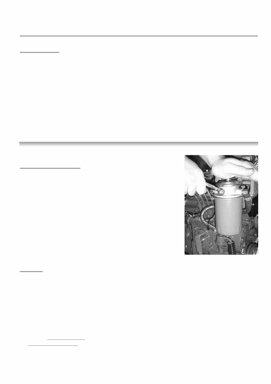
5 SECTION 1 GUIDELINES FOR OPERATION OF ENGINE IMPORTANT CHECKS PRIOR TO INITIAL USE 1. Generally a new engine has the oil and anti-freeze removed after the works test. Fill the engine with the correct oil and anti- freeze (see sections on ENGINE OIL and COOLING). Check gearbox oil level - see separate operator's hand book. 2. Ensure the engine is free to turn without obstructions. 3. Ensure battery is fully charged and connected (the isolator is in the 'ON' position). 4. Ensure Morse speed and gearbox cables are fitted correctly and that cable travel lengths are correct. Gear selection lever – all mechanical gearboxes: care must be taken to ensure that the remote control cable is adjusted so that the selector lever on the gearbox moves FULL travel and brought “hard up” against its end stop in both directions. Failure to achieve the correct adjustment will reduce efficiency of the clutch and may cause slippage at low revs. Warranty will not be accepted on gearboxes returned in the warranty period for failure due to incorrect adjustment. 5. Ensure engine is out of gear with 1/3 throttle - see single lever control instruction manual. 6. Open the fuel stopcock and bleed the fuel water separator of air as shown in manufacturers literature. 7. Fuel should now be at the fuel lift pump. See Fig 1a INITIAL STARTUP AND BLEEDING THE SYSTEM (a) Open fuel bleed screw on top of fuel filter by 1- 2 turns, see Fig 1a. (b) Move priming plunger on the fuel filter head up and down until fuel with no bubbles comes out of the bleed screw. (c) Shut/tighten the bleed screw. (d) Continue to hand prime for 10 seconds to push fuel through the fuel pump. (e) Start engine (see normal starting). Note: the engine may have to be turned over with the starter for a few seconds before it fires. Do not run the starter for more than 20 seconds. If the engine has not started after 20 seconds then disengage the starter and continue to hand prime for a further 30 seconds, then repeat. (f) If engine does not start after 3 attempts then allow 5 minutes for the starter to cool down before repeating (b) to (e). Note: The starter windings can be burnt out with continuous cranking. CAUTION To avoid personal injury: • Do not bleed a hot engine as this could cause fuel to spill onto a hot exhaust manifold creating a danger of fire. • Do not mix gasoline or alcohol with diesel fuel. This mixture can cause an explosion. • Do not get diesel on the flexible mounts – they will deteriorate rapidly if soaked in diesel. • All fuel must be removed from skin to prevent infection. Diagram 1a
This manual is a comprehensive maintenance and repair guide covering two models of diesel engines from Bukh Motors, namely BBD1105 and BBV1505. It is an invaluable resource for both professional mechanics and DIY enthusiasts.
Containing detailed information, this manual assists in fault identification, troubleshooting, and repair of engine components. It also provides assembly and dismantling instructions, along with precise diagrams for efficient service.
Topics covered in this manual include the general description and technical data, the electrical system, the lubrication and coolant systems, the fuel and air systems, the timing system, troubleshooting, and more.
Key features of this manual:
Comprehensive coverage of maintenance and repair instructions for two models of Bukh Motors diesel engines
Detailed guidance for fault identification, troubleshooting, and repair of engine components
Assembly and dismantling instructions with precise diagrams
In-depth coverage of the general description and technical data, electrical system, lubrication and coolant systems, fuel and air systems, timing system, and troubleshooting
This Operator's Maintenance Manual Volume 1 & 2 is an essential tool for ensuring the smooth operation of Bukh Equipment. It is a valuable resource for diesel engine technicians and is available for instant download.
Recently Viewed
5,521,897Happy Clients
2,594,462eManuals
1,120,453Trusted Sellers
15Years in Business
Price:
Actual Price:
Bukh Diesel engine type BBD1105 & BBV1505 Operator's Maintenance Manual