

BMW D12 Diesel Engine Workshop Manual
What's Included?
Fast Download Speeds
Online & Offline Access
Access PDF Contents & Bookmarks
Full Search Facility
Print one or all pages of your manual
Workshop
BMWD
Manual
12
BMW .Marine Engines
(1~
a;

0 0 0 0
BMW Dl 2 Marine engine
DESCRIPTION
The D 12 marine engine is a single-cylinder, four-stroke Diesel engine with direct injection. It features a single-circuit
cooling system. The coolant pump with Neoprene impeller is driven directly from the crankshaft. The A.C. generator
is located in the flywheel and, like the electric starter, is standard epuipment. The injection pump is driven from the
camshaft. The injection system bleeds itself automatically.
GENERAL
This manual describes the overhaul of the BMW D 12 marine engine when not installed. All removal, installation and
overhaul jobs on a specific assembly (component) are always combined into one section and named after the assembly.
The sequence of the sections corresponds to the job sequence in stripping the engine.
Additionally, at the beginning of each section the jobs are listed which are required to remove (overhaul) the assembly
(component) in each case, if the engine is not being completely stripped.
The job sequence for assembling the complete engine is given as a list of key words with the title “Job sequence in
assembling the engine” follçwing the overhaul sections.
The terms “top, bottom, front, rear, left, right” invariably are related, unless otherwise defined in the text, to the
installed position of the engine as viewed in the direction of travel.
C Figures in the manual are numbered consecutively throughout. When cross references are made to Figures in the
text, the Figure No. is given first, followed by the item No. in the Figure, e.g., (25/1) is a reference to Fig. 25, item 1.
1
BMW Dl 2 Marine engine
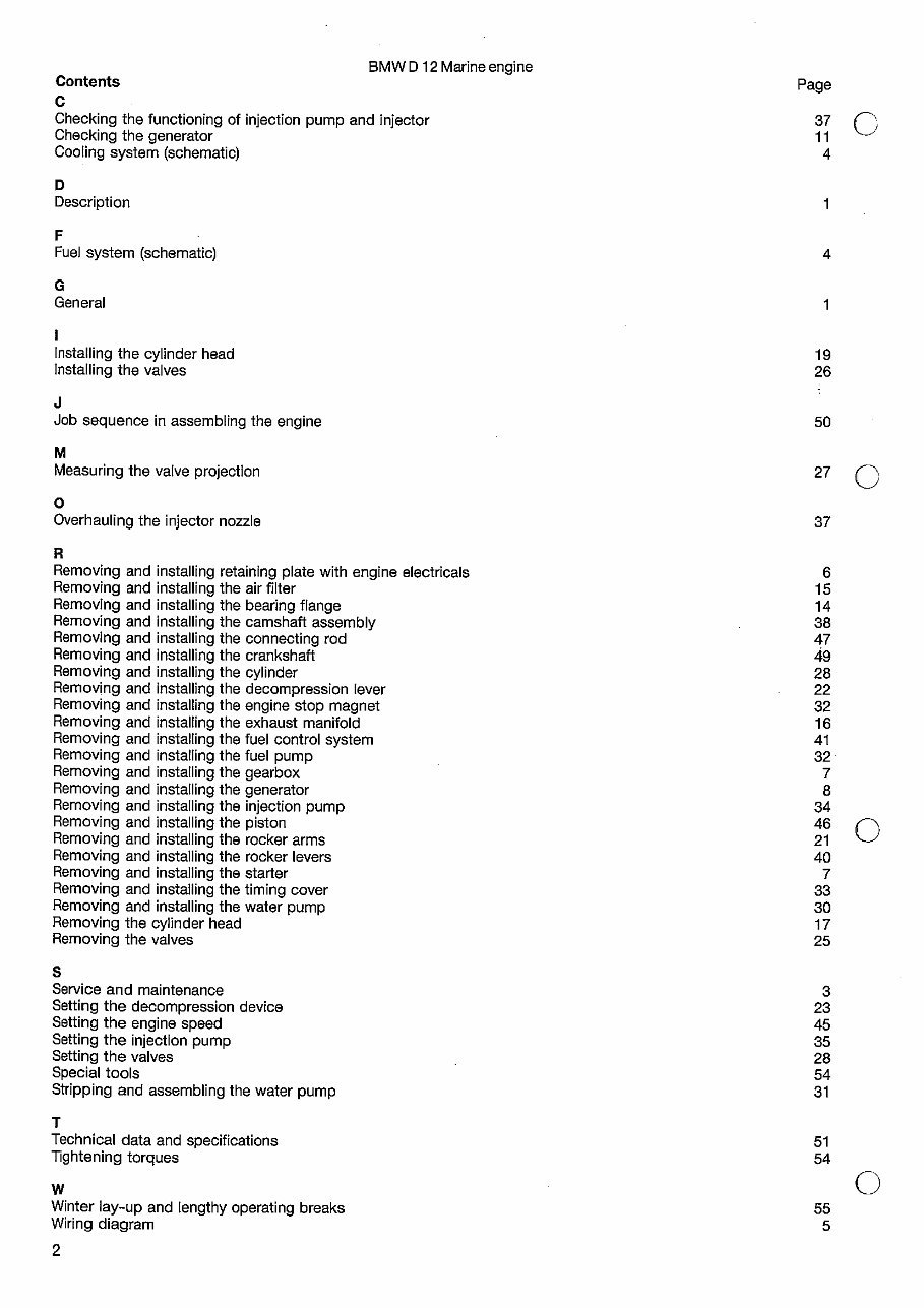
Contents Page
C
Checking the functioning of injection pump and injector
Checking the generator 11
Cooling system (schematic) 4
D
Description 1
F
Fuel system (schematic)
G
General 1
Installing the cylinder head 19
Installing the valves 26
J
Job sequence in assembling the engine 50
M
Measuring the valve projection 27 Q
0
Overhauling the injector nozzle 37
R
Removing and installing retaining plate with engine electricals 6
Removing and installing the air filter 15
Removing and installing the bearing flange 14
Removing and installing the camshaft assembly 38
Removing and installing the connecting rod 47
Removing and installing the crankshaft
Removing and installing the cylinder 28
Removing and installing the decompression lever 22
Removing and installing the engine stop magnet 32
Removing and installing the exhaust manifold 16
Removing and installing the fuel control system 41
Removing and installing the fuel pump 32
Removing and installing the gearbox
Removing and installing the generator 8
Removing and installing the injection pump
Removing and installing the piston 46
Removing and installing the rocker arms 21
Removing and installing the rocker levers 40
Removing and installing the starter 7
Removing and installing the timing cover 33
Removing and installing the water pump 30
Removing the cylinder head 17
Removing the valves 25
S
Service and maintenance
Setting the decompression device 23
Setting the engine speed
Setting the injection pump
Setting the valves 28
Special tools
Stripping and assembling the water pump 31
T
Technical data and specifications 51
Tightening torques
w 0
Winter lay-up and lengthy operating breaks 55
Wiring diagram 5
2
BMW Dl 2 Marine engine
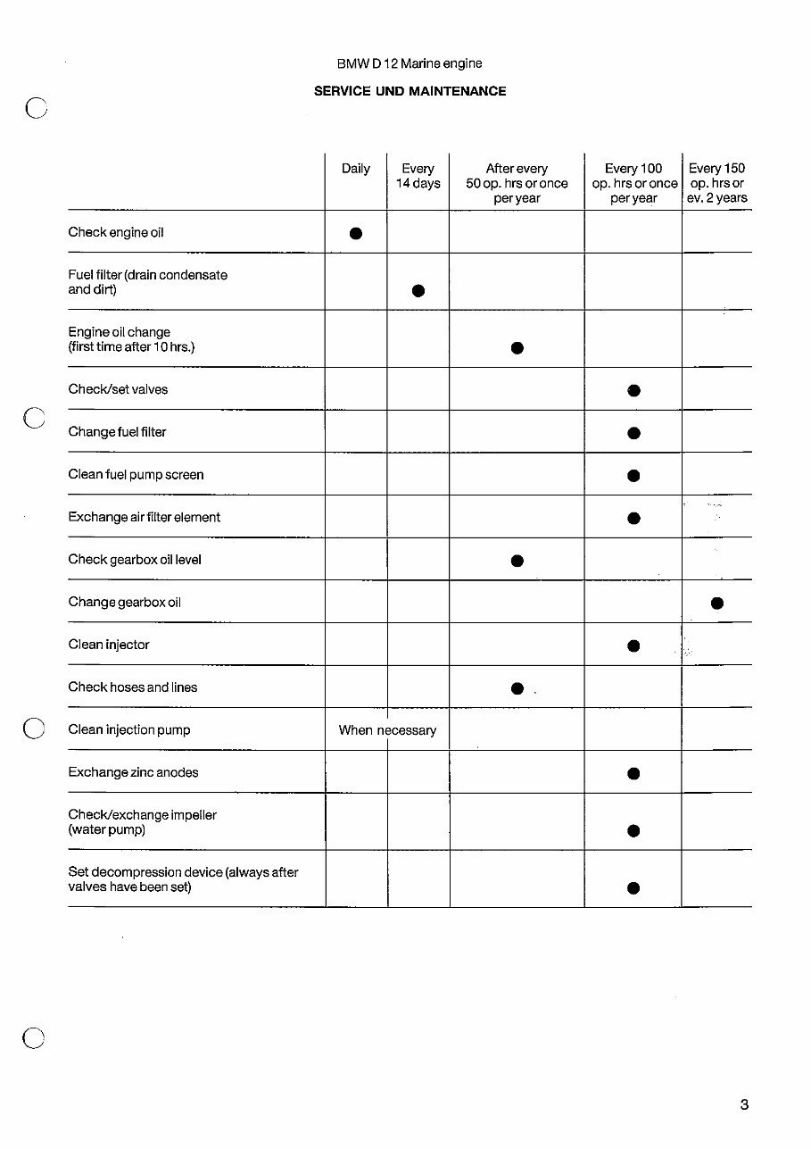
SERVICE UND MAINTENANCE
Daily Every After every Every 100 Every 150
14 days 50 op. hrs or once op. hrs or once op. hrs or
peryear per year ev. 2 years
Check engine oil
Fuel filter (drain condensate
ancidirt)
Engine oil change
(first time after 10 hrs.)
Check/set valves
Change fuel filter
Clean fuel pump screen
Exchangeairfilterelement
Check gearbox oil level
Change gearbox oil
Clean injector
Check hoses and lines
Clean injection pump When necessary
Exchange zinc anodes
Check/exchange impeller
(water pump)
Set decompression device (always after
valves have been set)
3
BMW Dl 2 Marine engine
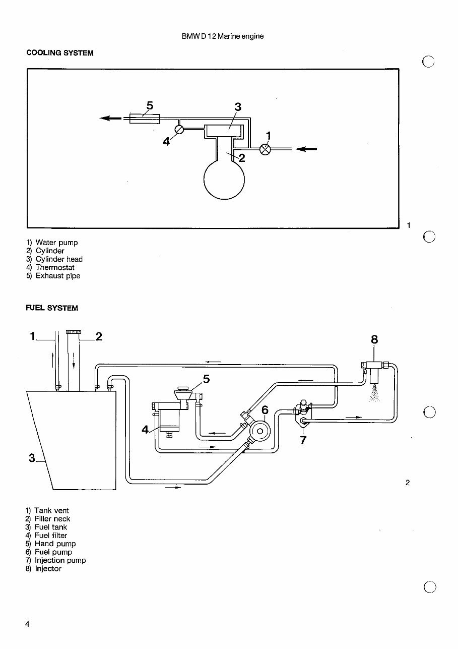
1) Water pump
2) Cylinder
3) Cylinder head
4) Thermostat
5) Exhaust pipe
1) Tank vent
2) Filler neck
3) Fuel tank
4) Fuel filter
5) Hand pump
6) Fuel pump
7) Injection pump
8) Injector
COOLING SYSTEM
4
3
1
FUEL SYSTEM
C
C
C
C
4
seen from C
tt~gue plug
3,’
*x** for optional warning
* connect wiring from fuel SNDR here
marking an
the wfrit~
—(INS TTh)
P1) purple violet!
ER brown bravo
R red rot
1 WSL white blue weillblau
GNSR greenbravs grdn braun
EL blue blau
• YR yellow red gelb rat
GY gn-y gnu
B black schwarz -
• EGN black greenschwarz groin
IV white welt)
BRED black red 5chwarz rot
BLGN blue goven Nov groin
a
-L
ND
D
CD
CD
D
(0
D
CD
** wiring homes f. opt. elektr Sumlog connect hg) disconnect wiring (GIL PRESS) t~lGi
?_ €~._._~J
L _
uw
LIGHT — 1,SSL
5,
/ ‘\
~ (sPne)
TT! i~sat#w
\J rINSTRZ- isa
INSTRt~ (sPu
LIGHT— Iss
—LIGHT 7,58
/ f’l ~-lNsTR I5PIJ
® ~58LB
LIGHT — ISEL
LIGHT
- Z58 -UGHT
C)
~SB
zz@~
colour
.—z5Pu--
C
448W ( TRIM
{SgW (TRIM .L_e PARE
15P1) (SUM.)—c
is SiN BIJZZER—~c]
IV
~56RED
isa
7V1——I
~j! ,,d,,oJu
rflL_ZSYR
,,SPU
iwo
7.5 SR
_—ct~._j ~
i5PCL —c 1
7,5GNBR j G;~~
1.5Pu —C ~~‘—‘~~1
~ _
Cl It
9 8 7 i.ceptacle
S 4 plug
flra~~’~
H H
I .4]—! I I
cJ LqJ 5)
— ISPU
— ISWSL
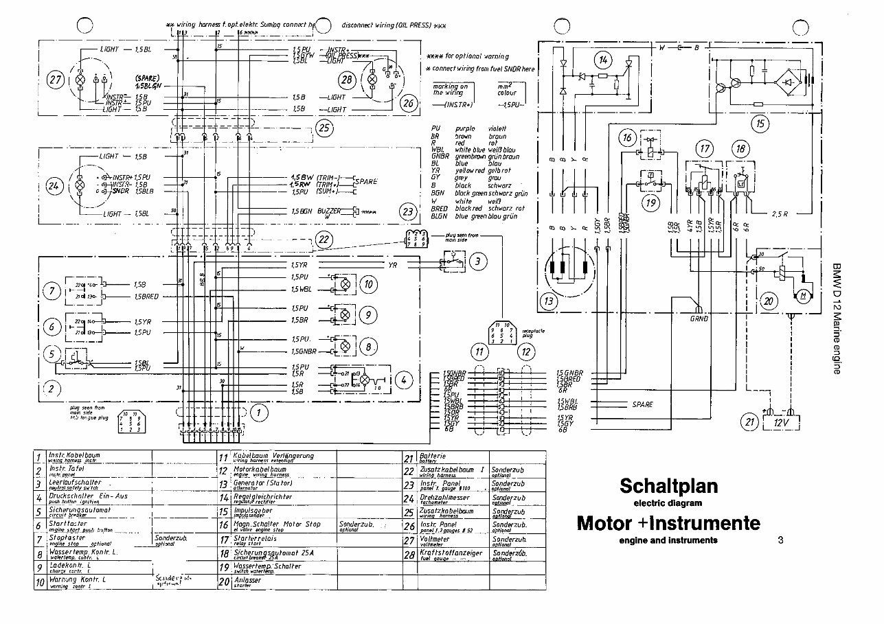
q TheIr Kabelboum 1 ii Kabelbaum Verl~noerung Sotterie
— wsq~g harness (coin -— flg harness emten lia,f batter,.
2 Insir. Ta tel 12 Natorkabetbaum 22 Zusatzkobelboun .1 Sanderzub
rn~er~pp__~_,_,~ ag/or w/rfoj~arness wlrfogharness ,.cpifonal
3 Leerlaufschallpr . 13 Genera tar (SIn tar) Instr. Panel Sondergub
neutral safety stitch .~ alternator pane’ t gauge •tao 0$/and!
4 Druckschnlter Ein-Aus 74j Regelgleichrichter 24 Drehzohlmesser Sanderzub
~,puohhuttan ;gn,t,an ergilat or reef/ftc, — tachometer ep~gpat -
5 I S/chrungsautomot 15 Impulsgeber 25 Zotzkobe!baum Sad erzub
~jc,rn,. I breaker — — -- ,4impaln.sader - —~ wiring harness aat,gnc - -—
6 Startto:ter 16 Mogn.Scha!ter Motor Stop Sonderiub.,- Instc Panel Sonderzub,
a,gfp~artp~~j bsttan el calve engIne stop optional — panel f.2gauges 052_- a~tianal
7 Sloptoster Sonderzub 77 Slarterrelais . Voltmeter Sanderiub.
engines tap optional apt/spat re lay start — uattmeler optiaral
o Ifossertemp. Konlr. L 15 Sicherunosar.otomot 25A 28 Krofl-stolfanzeiger Sonderzdb.
ealertemp. cant,. L circuit breakel 2~A fuel gauge - --
a Ladekantr. L 79~Wa5sertemP:SchoIter
char.. —c rant,. t I . — -switch waterttn.p.
in Ir/arnung Kontr. L SC.Ijderr O 20 L Anlasser
~ l.mrnirq cantr I ‘C””- starter
Schaltplan
electric diagram
Motor +lnstrumente
engine and instruments
3
BMW Dl 2 Marine engine
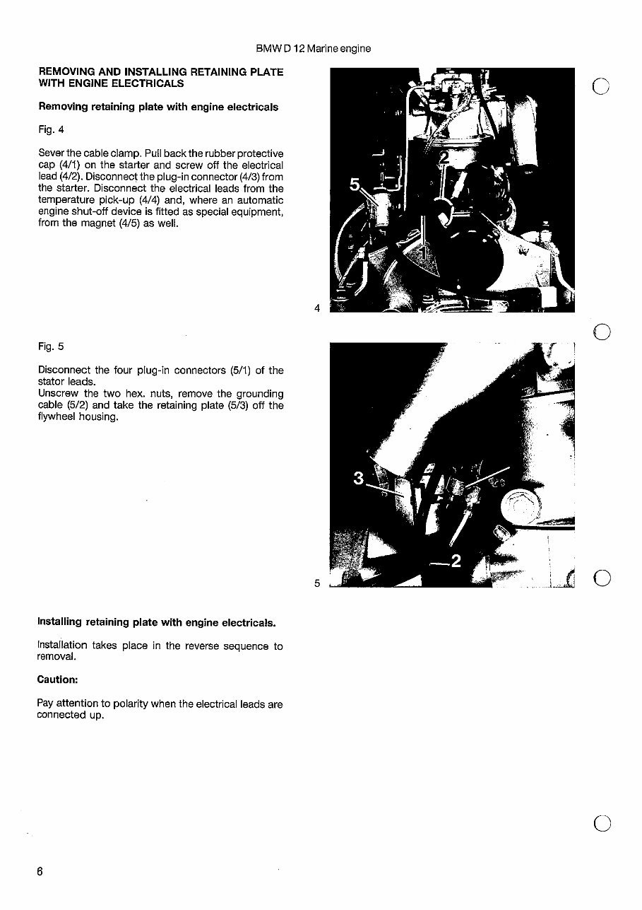
REMOVING AND INSTALLING RETAINING PLATE
WITH ENGINE ELECTRICALS
Removing retaining plate with engine electricals
Fig. 4
Sever the cable clamp. Pull back the rubber protective
cap (4/1) on the starter and screw off the electrical
lead (4/2). Disconnect the plug-in connector (4/3) from
the starter. Disconnect the electrical leads from the
temperature pick-up (4/4) and, where an automatic
engine shut-off device is fitted as special equipment,
from the magnet (4/5) as well.
Fig. 5
Disconnect the four plug-in connectors (5/1) of the
stator leads.
Unscrew the two hex. nuts, remove the grounding
cable (5/2) and take the retaining plate (5/3) off the
flywheel housing.
Installation takes place in the
removal.
Caution:
reverse sequence to
Pay attention to polarity when the electrical leads are
connected up.
0
0
0
C
Installing retaining plate with engine electricals.
6
BMW Dl 2 Marine engine
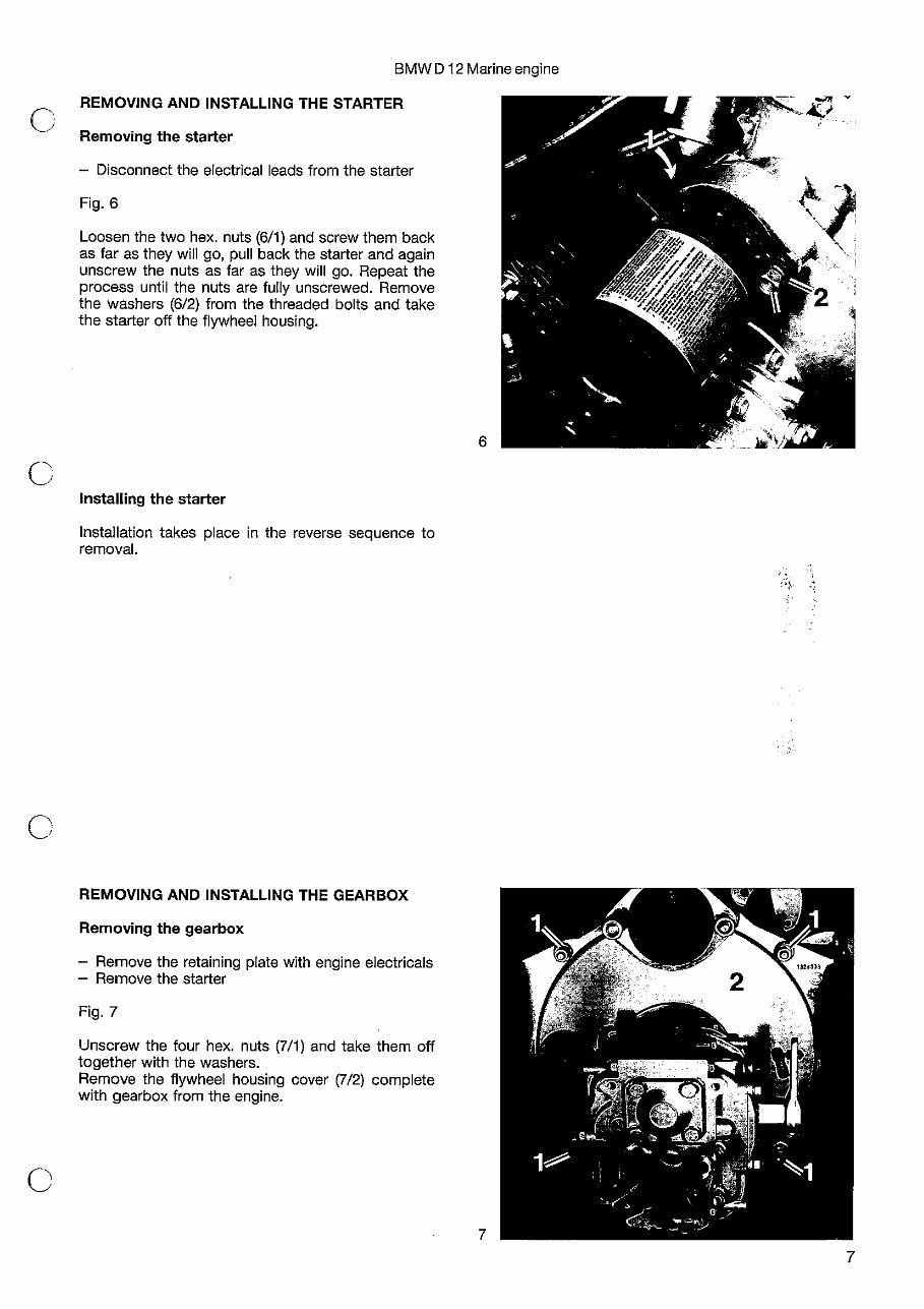
REMOVING AND INSTALLING THE STARTER
Removing the starter
— Disconnect the electrical leads from the starter
Fig. 6
Loosen the two hex. nuts (6/1) and screw them back
as far as they will go, pull back the starter and again
unscrew the nuts as far as they will go. Repeat the
process until the nuts are fully unscrewed. Remove
the washers (6/2) from the threaded bolts and take
the starter off the flywheel housing.
Installing the starter
Installation takes place in the reverse sequence to
removal.
REMOVING AND INSTALLING THE GEARBOX
Removing the gearbox
— Remove the retaining plate with engine electricals
— Remove the starter
Fig. 7
Unscrew the four hex. nuts (7/1) and take them off
together with the washers.
Remove the flywheel housing cover (7/2) complete
with gearbox from the engine.
7
Installing the gearbox
Installation of the gearbox takes place in the reverse
sequence to removal.
— Install the starter
— Install the retaining plate with engine electricals
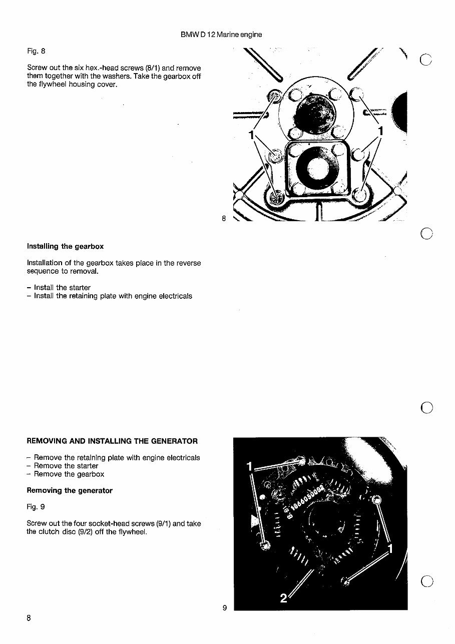
Fig. 8
Screw out the six hex.-head screws (8/1) and remove
them together with the washers. Take the gearbox off
the flywheel housing cover.
BMW Dl 2 Marine engine
F
0
0
0
REMOVING AND INSTALLING THE GENERATOR
— Remove the retaining plate with engine electricals
— Remove the starter
— Remove the gearbox
Removing the generator
Fig. 9
Screw out the four socket-head screws (9/1) and take
the clutch disc (9/2) off the flywheel.
8
You're Reading a Preview
What's Included?
Fast Download Speeds
Online & Offline Access
Access PDF Contents & Bookmarks
Full Search Facility
Print one or all pages of your manual
$26.99
Viewed 49 Times Today


Secure transaction
What's Included?
Fast Download Speeds
Online & Offline Access
Access PDF Contents & Bookmarks
Full Search Facility
Print one or all pages of your manual
$26.99
This manual is an essential resource for repairing and maintaining the BMW D12 diesel engine. It offers detailed information on engine components and systems, along with step-by-step instructions for maintenance and repairs.
It covers the following models:
- BMW D12 6.0L Diesel Engine
- BMW D12 6.6L Diesel Engine
- BMW D12 7.2L Diesel Engine
- BMW D12 8.0L Diesel Engine
In addition to troubleshooting information and diagrams, it provides detailed instructions for routine maintenance and tune-up procedures. Whether you're a professional mechanic or a DIY enthusiast, this manual is invaluable for keeping your BMW D12 diesel engine in top condition.


