

BETA Marine OPERATOR Maintenance Manual
What's Included?
Fast Download Speeds
Online & Offline Access
Access PDF Contents & Bookmarks
Full Search Facility
Print one or all pages of your manual
CALIFORNIA – Proposition 65 Warning: Diesel engine exhaust and some of its constituents are known
to the state of California to cause cancer, birth defects and other reproductive harm.
Operator’s
Maintenance
Manual
Heat Exchanger Cooled
Mid Diesel Engine Range
Beta 43, Beta 50 & Beta 60
Operator’s
Maintenance
Manual
Heat Exchanger Cooled
Mid Diesel Engine Range
Beta 43, Beta 50 & Beta 60
Downloaded from www.Manualslib.com manuals search engine
Engine Details
IMPORTANT - Please fill in details at moment of purchase - it really will
help you! (and it will really help us specify the correct spare parts for you).
Engine Type: Power: bhp Speed: rpm
BETA WOC NO:
K
Gearbox Type:
Purchased From:
Invoice No.:
Date Commissioned:
Specification / Special Details:
Downloaded from www.Manualslib.com manuals search engine

1
My engine details (to be completed now) Inside front cover
Introduction
Engine identification 2
Initial receipt of the engine 2
Engine storage 2
Safety precautions 3
Technical specifications 4
Section 1: Installation guidelines
Engine mounting 5
Engine alignment - drives, flanges, flexible couplings 6
Exhausts and mounting exhausts 7
Fuel supply and "leak off" 8
Cooling - sea water inlet system 9
Calorifier connections (if fitted) 9
Electrical Installation 10
Section 2: Guidelines for operation of the engine
Important checks prior to initial use 11
Initial start-up and bleeding the fuel system 11
Starting and stopping 13
Section 3: Maintenance & Service guidelines
Maintenance schedule 14
Lubrication - checking and changing oil 16
Fuel system - fuel/water separator, fuel lift pump, fuel filter 18
Cooling - fresh water system, heat exchanger 19
Sea water pump, heat exchanger 20
Belt tensioning adjustment 21
Air filter inspection / replacement 22
Electrical maintenance 22
Laying up - winterising 23
Troubleshooting 24
Torque settings 34
Wiring diagrams and general arrangement drawings index 35
Exhaust Emission - Declaration of Conformity 61
Exhaust Emission - Durability 62
Fast Moving Parts Listing 63
Maintenance record Inside back cover
Contents
Downloaded from www.Manualslib.com manuals search engine
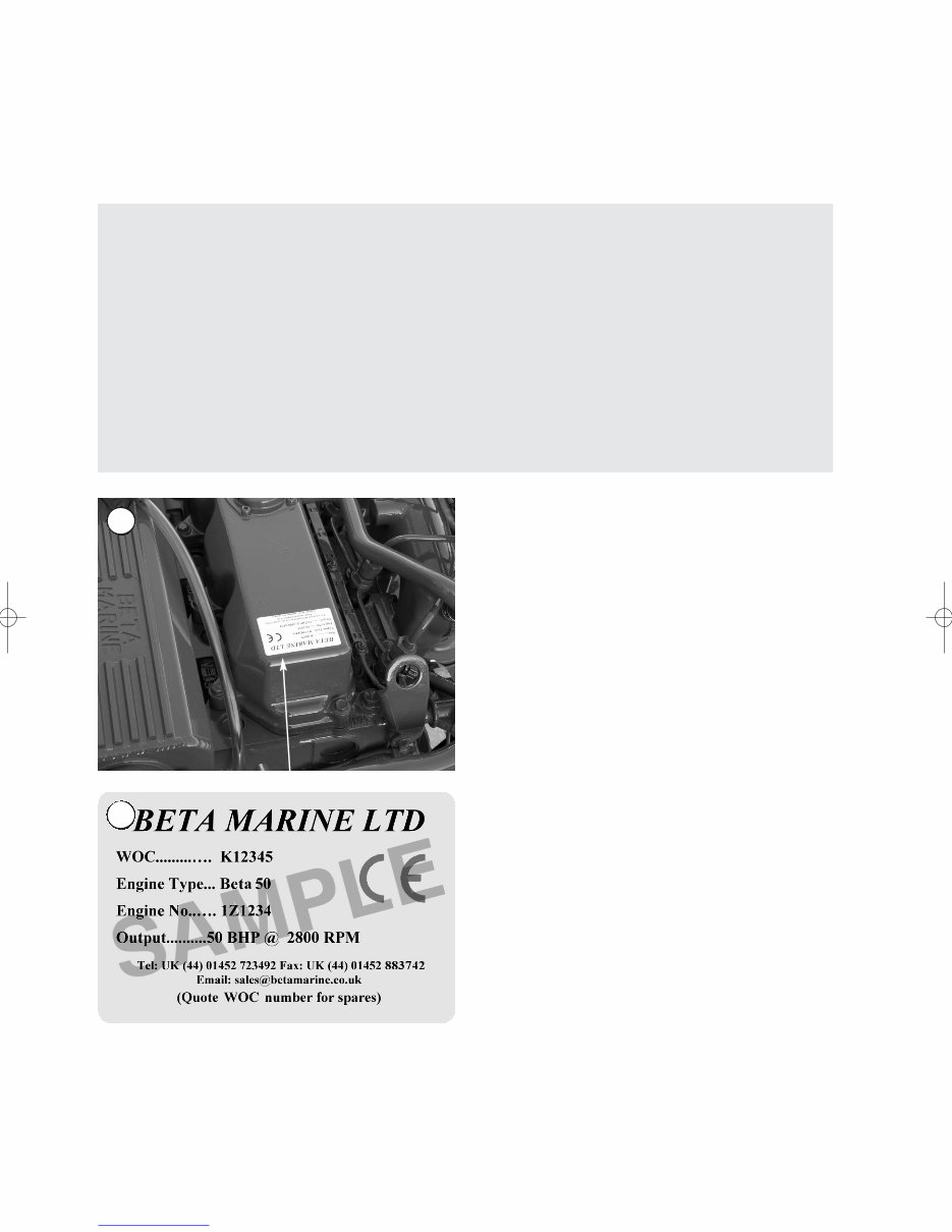
Engine Identification
NOTE: In all communications with the
distributor or Beta Marine, the W.O.C.
and engine number must be quoted.
Beta 43, Beta 50 and Beta 60
The engine serial number is stamped above starter motor on
the port side of the engine, and is shown on the rocker cover
label.
Initial Receipt of the Engine
A full inspection of the engine must be made immediately
on delivery to confirm that there is no damage. If there is
any damage then write this clearly on the delivery note and
inform your dealer or Beta Marine within 24 hours. A
photograph would always help.
Engine Storage
The engine must be stored in a dry, frost free area and this is
best done in its packing case. If storage is to be more than
six months then the engine must be inhibited (contact your
dealer or Beta Marine). Failure to inhibit the engine may
result in the formation of rust in the injection system and the
engine bores, this could invalidate the warranty.
OPERATION AND MAINTENANCE MANUAL FOR THE FOLLOWING
BETA MARINE ENGINES BASED ON KUBOTA SERIES
Beta 43, Beta 50 & Beta 60
2
1
2
This manual has been compiled to provide the user with important information and recommendations to ensure trouble free
and economical operation of the engine.
As manufacturers we have obviously written this “Operators Maintenance Manual’ from our ‘involved technical viewpoint’
assuming a certain amount of understanding of marine engineering. We wish to help you, so if you do not fully understand
any phrase or terminology or require any explanations please contact Beta Marine Limited or its distributors and we will be
pleased to provide further advice or technical assistance.
All information and recommendations given in this publication are based on the latest information available at the time of
publication, and are subject to alteration at any time.
The information given is subject to the company’s current conditions of Tender and Sale, is for the assistance of users, and
is based upon results obtained from tests carried out at the place of manufacture and in vessels used for development
purposes. We do not guarantee the same results will be obtained elsewhere under different conditions.
Downloaded from www.Manualslib.com manuals search engine
3
A Keep the engine, gearbox and surrounding area clean,
including the area immediately below the engine
B Drives - Power Take Off Areas
i) Gearbox Output Flange
The purpose of a marine diesel propulsion engine is to
provide motive power to propel a vessel. Accordingly the
gearbox output shaft rotates at between 280 and 2400
rev/min. This flange is designed to be coupled to a
propeller shaft by the installer and steps must be taken to
ensure adequate guarding.
ii) Forward End Drive
Engines are supplied with unguarded belt drives to power
the fresh water pump and battery charging alternator.
The installer must ensure that it is not possible for injury
to occur by allowing access to this area of the engine.
The three pulleys run at high speed and can cause injury
if personnel or clothing come in contact with the belts or
pulleys, when the engine is running.
iii) Power Take Off Shaft (Engine Mounted Option)
Shaft extensions are available as an option and rotate at
between 850 and 3600 rev/min. If contact is made with
this shaft when the engine is running, injury can occur.
C Exhaust Outlet
Diesel marine propulsion engines emit exhaust gases at
very high temperatures - around 400 - 500°C. Engines
are supplied with either wet exhaust outlet (water
injection bend) or dry outlet (dry exhaust stub) - see
option list. At the outlet next to the heat exchanger /
header tank, the exhaust outlet can become very hot and
if touched, can injure. This must be lagged or avoided by
ensuring adequate guarding. It is the responsibility of the
installer to lag the exhaust system if a dry system is used.
Exhaust gases are harmful if ingested, the installer must
therefore ensure that exhaust lines are led overboard and
that leakage in the vessel does not occur.
D Fuel
i) Fuel Lines
Diesel engines are equipped with high pressure fuel
injection pumps, if leakages occur, or if pipes fracture,
fuel at a high pressure can harm personnel. Skin must be
thoroughly cleaned in the event of contact with diesel
fuel.
ii) Fuel Supply Connections
Engines are supplied with 8mm compression fittings. The
installer must ensure that when connections are made,
they are clean and free of leaks.
E Oil
The Beta propulsion unit is supplied with 2 dipsticks, one
for the engine and one for the gearbox. Ensure dipsticks
are returned and secure after checking, if not oil leaks can
cause infection when touched. All oil must be removed
from the skin to prevent infection.
F Scalding
An engine running under load will have a closed circuit
fresh water temperature of 85° to 95°C. The pressure
cap on the top of the heat exchanger must not be
removed when the engine is running. It can only be
removed when the engine is stopped and has cooled
down.
G Transportation / Lifting
Engines are supplied on transportable pallets. Lifting eyes
on engines are used for lifting engine and gearbox
assembly only, not the pallet and associated kit.
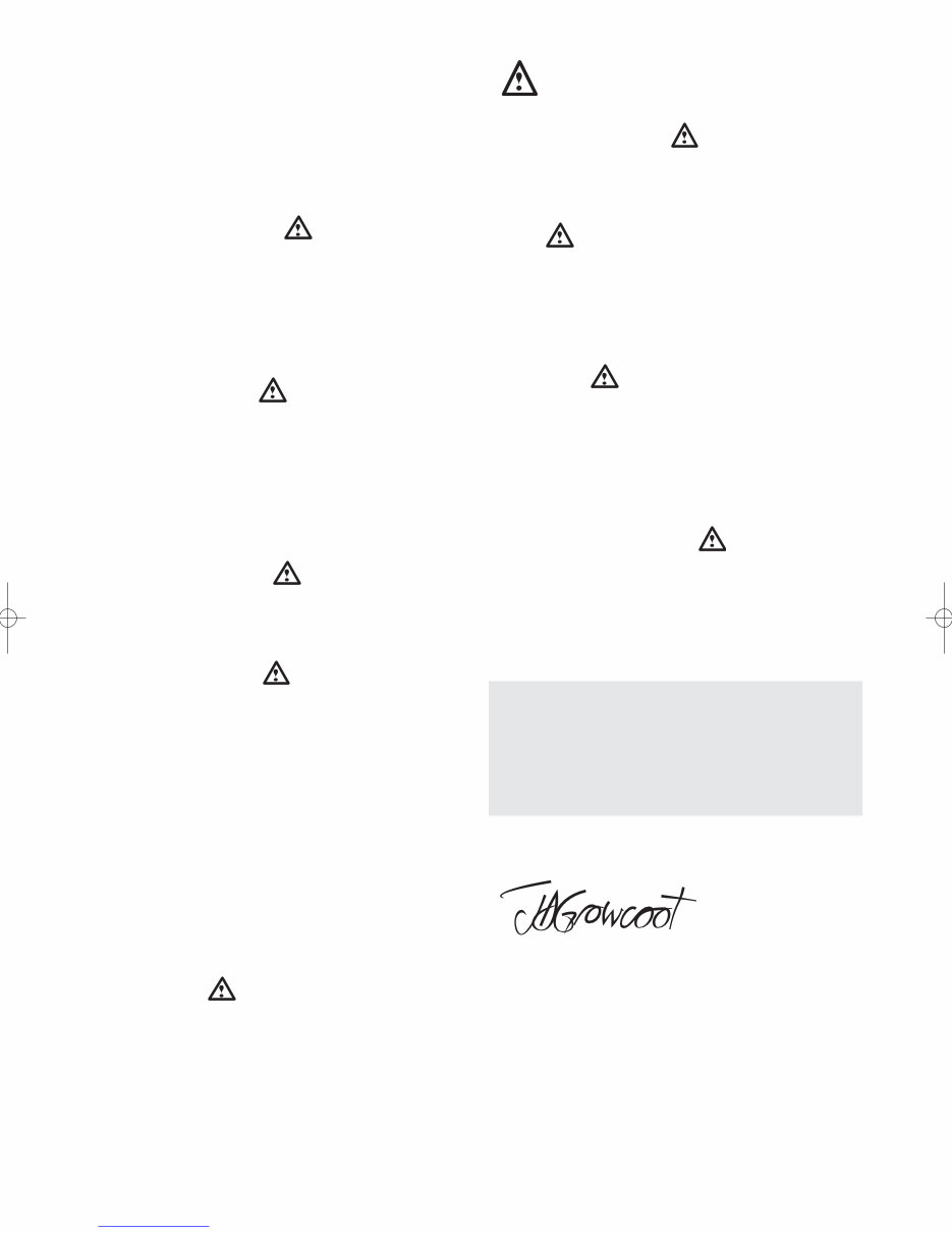
GENERAL DECLARATION
This machinery is not intended to be put into service until it
has been incorporated into or with other machinery. It is the
responsibility of the purchaser / installer / owner, to ensure
that the machinery is properly guarded and that all necessary
health and safety requirements, in accordance with the laws
of the relevant country, are met before it is put into service.
Signed:
J A Growcoot, C.E.O,
Beta Marine Limited
NOTE: Recreational Craft
Where applicable, the purchaser / installer / owner and
operator must be responsible for making sure that the
Recreational Craft Directive 94/25/EC is complied with.
Safety Precautions!
Downloaded from www.Manualslib.com manuals search engine

Maximum Angle of Installation: Trim 15°; Roll 25° (intermittent) or 20° continuous, see page 6.
Rotation: Anti-clockwise on flywheel, clockwise on output gearbox flange for use with right hand propeller in ahead, on
mechanical gearboxes. Hydraulic gearboxes can be left or right handed. Diesel fuel must conform to BS2869-1970 class A1
or A2. The fuel must be a distillate and not a residual oil or blend.
Lubricant:
Engine - engine oil must meet API Classification CF (CD or CE), See section 2 for details
Gearbox - see gearbox operator’s manual for the gearbox oil type and capacity
Oil pressure - minimum (tickover) 0.5 bar
Power outputs: These comply with BS EN ISO 8665:1996 crankshaft power
Note: Declared Powers to ISO8665:1996
1. The declared powers are at the same engine speed as the ISO 3046 figures. This speed is the speed related to the
outputs / powers shown.
2. Declared powers are at the gearbox coupling (coupling to the propeller shaft) as per clause 3.2.1 with standard
specifications as per our current price lists. Additional accessories or alternative gearboxes may affect the declared powers.
3. Operation at parameters outside the test parameters may affect the outputs / powers which in any case are subject to the
ISO tolerance bands.
Standard Engines Beta 43 Beta 50 Beta 60
Cylinder 4 4 4
Bore (mm) 83 87 87
Stroke (mm) 92.4 92.4 102.4
Displacement (cc) 1999 2197 2434
Combustion 3 Vortex 3 Vortex 3 Vortex
Cooling Water Water Water
Starter voltage (V) 12 12 12
Starter output (kW) 1.4 1.4 2.0
Starter alternator output (Amps) 65 (standard) 65 (standard) 65 (standard)
Glow plug resistance (each) 1Ω 1Ω 1Ω
Engine speed (RPM) 2,800 2,800 2,700
Power output to ISO3046 (BHP) 43.0 50.0 56.0
Declared power ISO8665 (kW) 31.0 36.1 40.6
Compression Ratio 23.0:1 23.0:1 23.0:1
Fuel timing BTDC 18° 18° 18°
Capacity of standard sump approx. (litres) 9.5 9.5 9.5
Capacity of shallow sump approx. (litres) 7.0 7.0 7.0
Nett dry weight with gearbox (kg) 270 300 310
Fuel Diesel fuel oil No.2D
Coolant 33%-50% maximum antifreeze:water
Coolant capacity approx.. (H/E litres) 7.4 7.4 7.4
Min. recommended battery capacity 12V, 120Ah (600 CCA Min)
4
Technical Specifications
Downloaded from www.Manualslib.com manuals search engine
5
Installation Recommendations
The installation details are basic guidelines to assist installation, however due to the great diversity of marine craft it is
impossible to give definitive instructions. Therefore Beta Marine can accept no responsibility for any damage or injury incurred
during the installation of a Beta Marine Engine whilst following these guidelines.
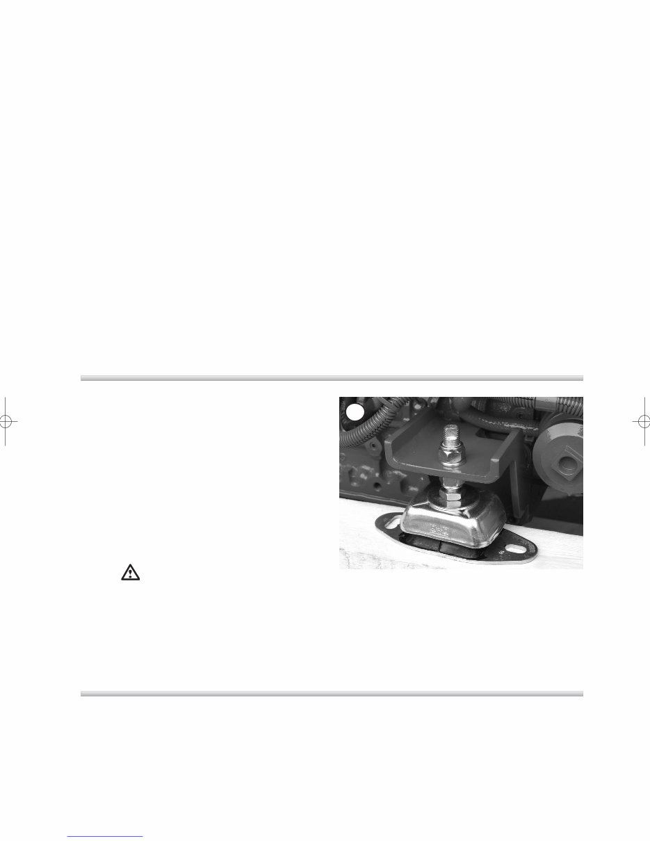
Engine Mounting
To ensure vibration free operation, the engine must be
installed and correctly aligned on substantial beds, extending
as far forward and aft as possible, well braced and securely
fastened to form an integral part of the hull.
The engine must be installed as low as possible on the
flexible mount pillar stud. This will limit vibration and extend
the life of the flexible mount. To assist with engine
replacement we offer ‘Special Engine Feet’ manufactured to
your dimensions, as an optional extra to suit your existing
engine bearers and shaft alignment/installation.
Warning
(1) Do not set the engine feet high up the flexible mount
pillar stud. This will cause excessive engine movement
and vibration. Pack under the flexible mount with steel
shims securely bolted into the engine bearer.
(2) The pillar stud on the flexible mount is secured into
position by the lower locknut, do not forget to tighten
this. Also ensure that the stud is not screwed too far
through the mounting body so that it can touch the
bearer. This will cause vibration and knocking noises
which are very hard to find!
Section 1
Flexible Output Couplings
A flexible coupling should be mounted on the gearbox output
flange and is strongly recommended in almost every case.
Flexible couplings do not accommodate bad alignment, they
are designed to absorb torsional vibrations from the propeller
(transmitted along the propeller shaft).
3
• All engines shall be placed within an enclosure separated
from living quarters and installed so as to minimise the
risk of fires or spread of fires as well as hazards from toxic
fumes, heat, noise or vibrations in the living quarters.
• Unless the engine is protected by a cover or its own
enclosure, exposed moving or hot parts of the engine that
could cause personal injury shall be effectively shielded.
• Engine parts and accessories that require frequent
inspection and / or servicing must be readily accessible.
• The insulating materials inside engine spaces shall be
non-combustible.
• Adequate ventilation must be included with every engine
installation. It is very important that the engine
compartment is ventilated, as the engine will produce
radiated heat - approximately equal to
1
/
3
of the engine
output power. Also the 65 and/or 100 amp battery
charging alternator/s create lots of heat. In yachts we
recommend forced ventilation using an extraction fan to
draw out the hot air and limit the maximum engine
compartment /room temperature to 60°C. This can be
checked with a thermometer on a hot day - the cooler the
engine compartment the better. A symptom of overheating
problems is black belt dust. It is normally best with two
ventilation holes; an inlet of at least 300 cm
2
allowing
colder air to enter near to the alternator and drive belts
and a second outlet (a third bigger than the inlet) for the
hot air to rise and ventilate out from the top of the engine
compartment using the cooling fan.
Downloaded from www.Manualslib.com manuals search engine
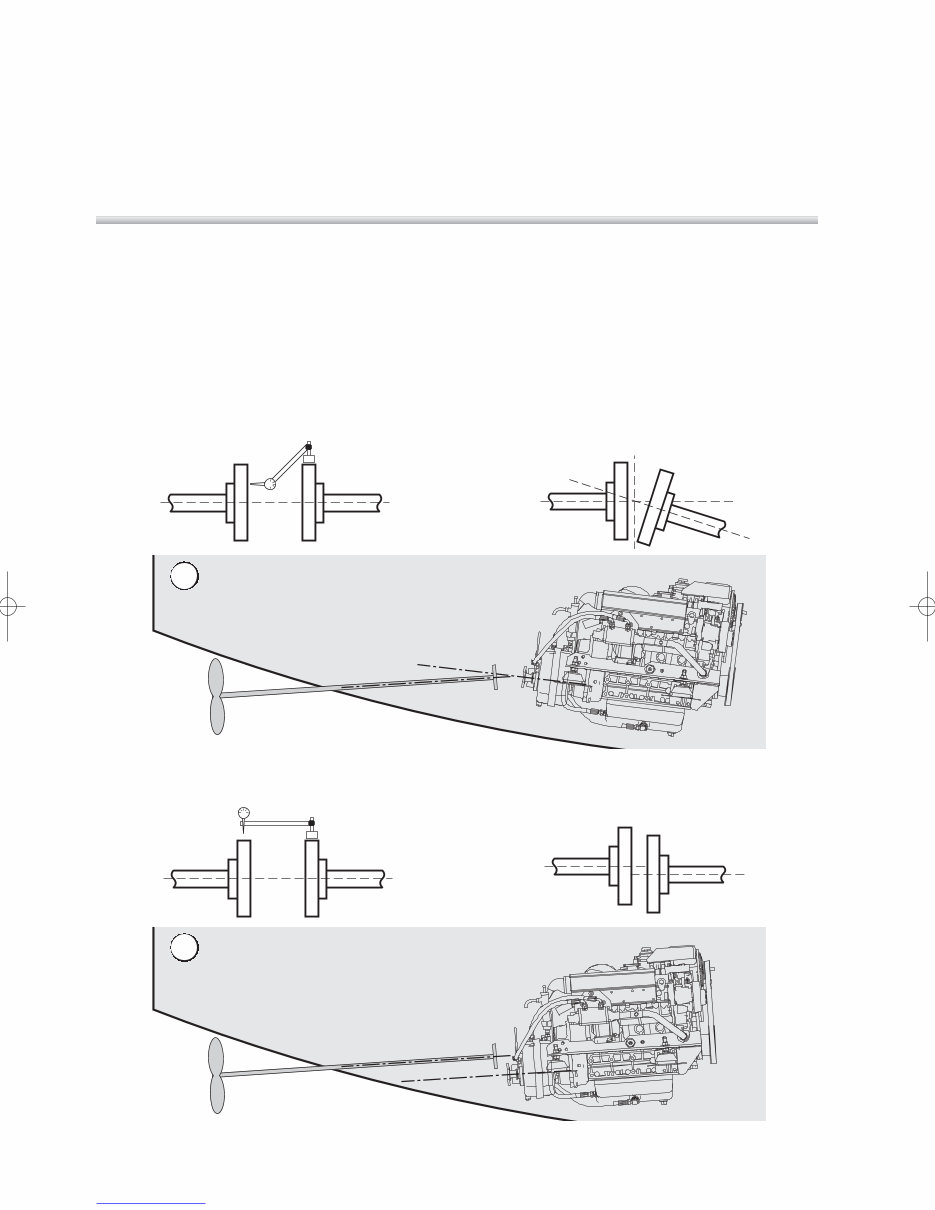
4 Angular Mis-alignment
Angular Mis-alignment
Engine / gearbox
flange
Propeller
shaft
Alignment
To obtain accurate alignment the flexible mountings must be
adjusted until alignment is attained, and the mountings must
be locked in position.
The engine/gearbox unit has to be aligned with the propeller
shaft in two ways. The traditional engine alignment method
involves measuring with either feeler gauges or a DTI (Dial
Test Indicator) mounted on a magnetic foot so that they are
aligned within 0.125mm (0.005”).
The engine mountings and the couplings must now be tightened in position and the alignment re-checked.
6
Engine Installation at an Angle
Beta Marine propulsion engines can be installed at angles up
to a maximum of 15° flywheel up or flywheel down when
static, or can be run at up to 25° when heeling. When our
engines are installed at varying angles of inclination the
normal markings on the dipstick should be disregarded.
It is probably better to totally drain the lubricating oil from the
sump, replacing the oil filter with a new one; then add the
recommended amount of lubricating oil – noting its position
on the dipstick – and then marking the dipstick. If in doubt
ask Beta Marine.
Angular Alignment
5 Parallel Mis-alignment
Parallel Mis-alignment
Engine / gearbox
flange
Propeller
shaft
Parallel Alignment
Downloaded from www.Manualslib.com manuals search engine
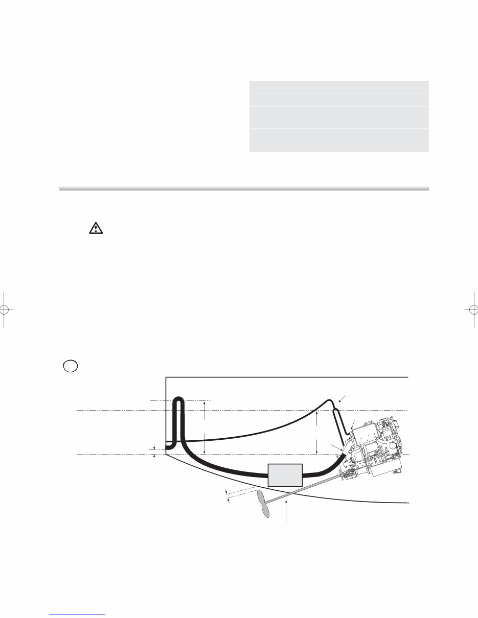
Typical Yacht Exhaust Installation
Warning
(1) One of the most common problems with engine
installations (and possibly expensive), is water entering
the engine exhaust manifold from the exhaust system by
syphoning when the engine is switched off. This can
occur when the point of water injection "X" on the engine
is close to or below the water line. Water entering the
pistons can cause bent con rods, emulsified engine oil
and a wrecked fuel pump! It’s best avoided!
(2) This diagram shows a typical exhaust installation.
The rubber hose connecting the heat exchanger to the
injection bend must be replaced by a hose (a) of
sufficient length, connecting to a "T" piece or anti-syphon
valve that is above the maximum seawater level when
heeled (at least 30 cms / 12 inches above the water line)
on the centre line of the boat. The pipe then returns to
the injection bend and the seawater is pumped down the
exhaust pipe.
(3) The exhaust back pressure should NOT exceed
62 mm Hg (2.4 inches Hg).
Exhausts
(a) An engine correctly installed in accordance with this
handbook will meet the emission requirements of the
RCD (see page 64).
(b) Keep dry exhaust systems to a minimum length and have
swept bends (NOT right angle elbows). Exhaust back
pressure is increased by longer exhaust length and sharp
bends. Back pressure should be measured; with the
complete exhaust system connected and the engine
running at full speed; and should NOT exceed 62 mm
Hg (2.4 inches Hg). The correct measuring point is before
the injection bend (at the manifold flange).
Wet Exhaust hose should be matched to the injection
bend sizes detailed below.
7
Exhaust Beta 43 Beta 50 Beta 60
Standard 50 mm 50 mm 50 mm
High rise water 50 mm 50 mm 50 mm
injection bend SS
Cross over water 50 mm 50 mm 50 mm
injection bend SS
Normal Seawater Level
Anti syphon valve or
T piece fitted here
Propeller Clearance:
between tip of propeller blade and underside
of hull should be at least 10 percent of the
propeller blade diameter
If a rope cutter is fitted, allow approximately 1/2”
for movement of engine, see manufacturer’s literature
30 cm
minimum
Maximum Seawater level
when heeled (measured on
the centre line of the boat)
40 cm
minimum
a
X
5 cm
minimum Waterlock
Silencer
6
Downloaded from www.Manualslib.com manuals search engine
8
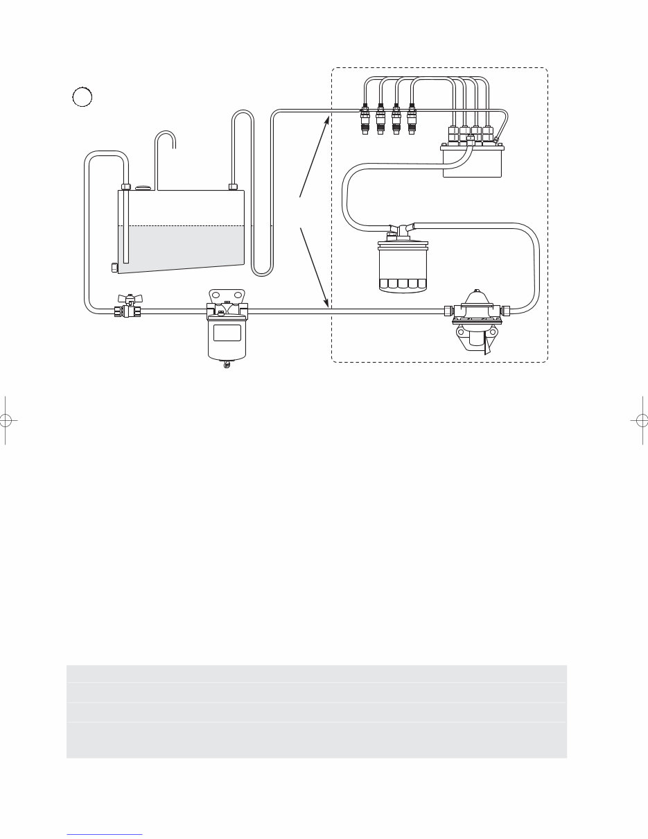
Fuel supply & leak off
Fuel tank
Stop tap/valve
Fuel/water
separator
Fuel filter
Fuel lift pump
Fuel injection
pump
Engine (All Fuel Connections Supplied)
Flexible Fuel
Connections
to be used
Fuel injectors
7
Notes:
1) A fuel/water separator must be installed.
2) The mechanical fuel lift pump is fitted to all engines as
standard, but if a suction head of 0.25m or more is
required, then an electric fuel lift pump must be fitted
(ask your dealer or Beta Marine).
3) It is very important that the excess fuel from the injectors
is fed back to the fuel tank and not back to any point in
the supply line. This will help prevent air getting into the
system.
4) The fuel return (leak off) pipe must loop down to be level
with the bottom of the tank before it enters the top of the
tank – see drawing. This prevents fuel ‘drain down’.
5) Fuel lines and hoses connecting the fuel tank to the
engine, must be secured, separated and protected from
any source of significant heat. The filling, storage,
venting, fuel supply arrangements and installation must
be designed and installed so as to minimise the risk of
fire. When connecting the engine to the fuel supply and
return lines, flexible fuel hoses must be used (next to the
engine) and must meet the requirements set in standard
ISO7840:1995/A1:2000 and/or as required by your
surveyor / authority.
6) Any fuel leaks in the system when static are likely to
cause poor starting and erratic running and must be
corrected immediately. These leaks will allow air to be
sucked in when the engine is running.
Engine Connections
Actual Connector: Required Pipe Size:
Fuel supply and fuel leaf-off connections are 8 mm conex with olives 8 mm O.D piping for both with flexible section
Seawater cooling pump connections are 28 mm OD Engine Inlet = 28 mm I.D hose
Water injected exhaust elbow outlet 50 mm OD Flexible exhaust rubber pipe to correct quality
- 50 mm OD
Vent
Downloaded from www.Manualslib.com manuals search engine
You're Reading a Preview
What's Included?
Fast Download Speeds
Online & Offline Access
Access PDF Contents & Bookmarks
Full Search Facility
Print one or all pages of your manual
$28.99
Viewed 87 Times Today


Secure transaction
What's Included?
Fast Download Speeds
Online & Offline Access
Access PDF Contents & Bookmarks
Full Search Facility
Print one or all pages of your manual
$28.99
Get the comprehensive operator maintenance manual for Beta Marine engines based on the Kubota Mini Series. This manual covers the following models:
- Beta 10
- BZ482
- Beta 16 (BZ602)
- BD722
- Beta 25 (BD902)
These manuals are invaluable resources for both professional mechanics and DIY enthusiasts.


