


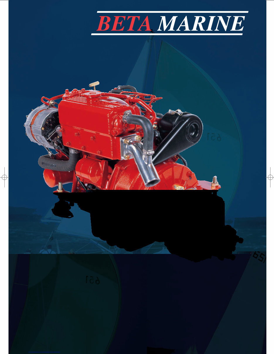
Operator’s
Maintenance
Manual
CALIFORNIA – Proposition 65 Warning: Diesel engine exhaust and some of its constituents are known to the state of
California to cause cancer, birth defects and other reproductive harm.
Heat Exchanger Cooled
Small Diesel Engine Range
BD1005, BV1305 and BV1505
Downloaded from www.Manualslib.com manuals search engine

Engine Details
Engine Type: Power: bhp Speed: rpm
BETA WOC NO: K Engine Serial No:
Gearbox Type: Serial No: Ratio :1
Purchased from:
Invoice No: Date:
Date Commissioned:
Specification / Special Details
IMPORTANT – Please fill in details at moment of purchase – it really will
help you! (and it will really help us specify the correct spare parts for you).
Downloaded from www.Manualslib.com manuals search engine

1
INTRODUCTION 2
Engine identification 2
Initial receipt of the engine 2
Engine storage 2
SAFETY PRECAUTIONS 3
TECHNICAL SPECIFICATIONS 4
SECTION 1: GUIDELINES FOR OPERATION OF ENGINE
Important checks prior to initial use 5
Initial start-up and bleeding the fuel system 5
Starting/stopping 6
SECTION 2: MAINTENANCE AND SERVICE GUIDELINES
Maintenance schedule: 7
Lubrication – checking and changing oil 8
Fuel system - pumps, filter, fuel/water separator 9
Cooling - fresh water system, keel cooling, heat exchanger 11
Sea water pump, heat exchanger 11
Belt tensioning 12
Air filter 13
Electrical 13
Laying up - winterising 13
Troubleshooting 15
Torque settings 25
SECTION 3: INSTALLATION GUIDELINES
Engine mounting 26
Alignment - drives, flanges, flexible drives 26
Exhausts & mounting exhausts 27
Fuel supply 28
Cooling - sea water inlet system 29
Calorifier system 30
Electrical and installations 31
Appendices –wiring diagrams and general arrangements 32
Component identification at rear of manual. 62
Maintenance record 65
Contents
Downloaded from www.Manualslib.com manuals search engine
OPERATION AND MAINTENANCE MANUAL FOR THE FOLLOWING
BETA MARINE ENGINES BASED ON KUBOTA SUPER 5 SERIES
BD1005, BV1305, BV1505
2
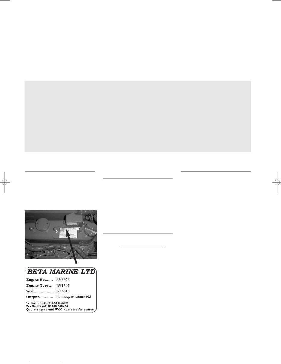
ENGINE IDENTIFICATION
NOTE: In all communications with
the distributor or Beta Marine, the
engine number, type, and W.O.C.
number must be quoted.
BD1005, BV1305,
BV1505
The engine serial number is stamped
above starter motor on the port side
of the engine, and is shown on the
rocker cover label.
INITIAL RECEIPT
OF THE ENGINE
A full inspection of the engine must
be made immediately on deliver y to
confirm that there is no damage. If
there is any damage then write this
clearly on the delivery note and
inform your dealer or Beta Marine
within 24 hours.
ENGINE STORAGE
The engine must be stored in a dry,
frost free area and this is best done in
its packing case. If storage is to be
more than six months then the
engine must be inhibited (contact
your dealer or Beta Marine). Failure
to inhibit the engine may result in the
formation of rust in the injection
system and the engine bores, this
could invalidate the warranty.
This manual has been compiled to
provide the user with important
information and recommendations
to ensure a trouble free and
economical operation of the
engine.
For further advice or technical
assistance, application should be
made to BETA MARINE LIMITED
or its distributors.
All information and
recommendations given in this
publication are based on the latest
information available at the time of
publication, and are subject to
alteration at any time. The
information given is subject to the
company’s current conditions of
Tender and Sale, is for the
assistance of users, and is based
upon results obtained from tests
carried out at the place of
manufacture and in vessels used
for development purposes. We do
not guarantee the same results will
be obtained elsewhere under
different conditions.
SAMPLE
Downloaded from www.Manualslib.com manuals search engine
3
A Keep the engine, gearbox
below the engine
B DRIVES - Power Take Off
Areas
i) Gearbox Output Flange
The purpose of a marine diesel
propulsion engine is to provide
motive power to propel a vessel.
Accordingly the gearbox output
shaft rotates at between 280 and
2400 rev/min. This flange is
designed to be coupled to a
propeller shaft by the installer
and steps must be taken to
ensure adequate guarding.
ii) Forward End Drive
Engines are supplied with
unguarded vee belt drives to
power the fresh water pump and
battery charging alternator. The
installer must ensure that it is not
possible for injury to occur by
allowing accessibility to this area
of the engine. The three pulleys
run at high speed and can cause
injury if personnel or clothing
come in contact with the belts or
pulleys, when the engine is
running.
iii) Power Take Off Shaft
(Engine Mounted Option)
Shaft extensions are available as
an option and rotate at between
850 and 3600 rev/min. If
contact is made with this shaft
when the engine is running,
injury can occur.
C EXHAUST OUTLET
Diesel marine propulsion engines
emit exhaust gases at very high
temperatures - around 400-
500°C. Engines are supplied with
either wet exhaust outlet (water
injection bend) or dry outlet (dry
exhaust stub) - see option list. At
the outlet next to the heat
This must be lagged or avoided by
ensuring adequate guarding. It is
the responsibility of the installer to
lag the exhaust system if a dry
system is used. Exhaust gases
are harmful if ingested, the
installer must therefore ensure that
exhaust lines are lead overboard
and that leakage in the vessel
does not occur.
D FUEL
i) Fuel Lines
Diesel engines are equipped with
high pressure fuel injection
pumps, if leakages occur, or if
pipes fracture, fuel at a high
pressure can harm personnel.
Skin must be thoroughly cleaned
in the event of contact with diesel
fuel.
ii) Fuel Supply Connections
Engines are supplied with 8 mm
compression fittings. The
installer must ensure that when
connections are made, they are
clean and free of leaks.
E OIL
The Beta propulsion is supplied
with 2 dipsticks, one for the
engine and one for the gearbox.
Ensure dipsticks are returned and
secure after checking, if not oil
leaks can cause infection when
touched. All oil must be
removed from the skin to prevent
infection.
F SCALDING
An engine running under load will
have a closed circuit fresh water
temperature of 85° to 95°C. The
pressure cap on the top of the
heat exchanger must not be
removed when the engine is
running. It can only be removed
when the engine is stopped and
has cooled down.
G TRANSPORTATION/
transportable pallets. Lifting eyes
on engines are used for lifting
engine and gearbox assembly
only, not the pallet and
associated kit.
GENERAL DECLARATION
This machinery is not intended to
be put into service until it has been
incorporated into or with other
machinery. It is the responsibility of
the purchaser/installer/owner, to
ensure that the machinery is
properly guarded and that all
necessary health and safety
requirements, in accordance with
the laws of the relevant country, are
met before it is put into service.
Signed:
J A Growcoot, C.E.O,
Beta Marine Limited
NOTE: Recreational Craft
Where applicable, the
purchaser/installer/owner and operator
must be responsible for making sure
that the Recreational Craft Directive
94/25/EC is complied with.
SAFETY PRECAUTIONS!
Downloaded from www.Manualslib.com manuals search engine

TECHNICAL SPECIFICATIONS
Maximum Angle of Installation: Trim 15°, Roll 30° (intermittent), 20° continuous
Rotation: ANTI CLOCK ON FLYWHEEL, CLOCKWISE ON OUTPUT GEARBOX FLANGE FOR USE WITH RIGHT HAND PROP IN AHEAD, on mechanical gearboxes. Hydraulic gearboxes can
be left or right handed.
Diesel fuel must conform to BS2869-1970 class A1 or A2. The fuel must be a distillate and not a residual oil or blend.
Lubricant: Engine - Engine oil must meet MIL-L-2104C (see section 2 for details)
Gearbox - see operator’s manual for the gearbox oil type and capacity
Oil pressure – minimum (tickover) 0.5 bar
Power outputs: These comply with BS EN ISO 8665:1996 crankshaft power
Note: Declared Powers to ISO8665:1995
1. The declared powers are at the same engine speed as the ISO 3046 figures. This speed is the speed related to the outputs / powers shown.
2. Declared powers are at the gearbox coupling (coupling to the propeller shaft) as per clause 3.2.1 with standard specifications as per our current price lists.
Additional accessories or alternative gearboxes may affect the declared powers.
3. Operation at parameters outside the test parameters may affect the outputs / powers which in any case are subject to the ISO tolerance bands.
Standard Engines BD1005 BV1305 BV 1505
Cylinder 3 4 4
Bore (mm) 76 76 78
Stroke (mm) 73.6 73.6 74.8
Displacement (cc) 1001 1335 1498
Combustion
Cooling
Starter voltage (V)
Starter output (kW)
Starter alternator output (Amps)
Glow plug resistance (each)
Engine speed (RPM)
Power output to ISO3046 (BHP) 28.0 35.0 37.5
Declared power ISO8665 (kW) 19.2 25.7 27.1
Compression Ratio
Fuel timing BTDC
Capacity of standard sump approx (litres) 6 7.5 7.5
Capacity of shallow sump approx (litres) 5 6.5 6.5
Nett dry weight with gearbox (kg) 150 170 170
Fuel
Coolant
Coolant capacity approx (H/E litres) 5.5 7 7
Min. recommended battery capacity
3 Vortex
Water
12
1.2
65 (standard)
21°
Diesel fuel oil No.2D
33%-50% maximum antifreeze / water
12V 80Ah (400CCA Min)
4
3,600 3,600 3,000
Downloaded from www.Manualslib.com manuals search engine
CAUTION
To avoid personal injury:
• Do not bleed a hot engine as this
could cause fuel to spill onto a hot
exhaust manifold creating a danger
of fire.
• Do not mix gasoline or alcohol
with diesel fuel. This mixture can
cause an explosion.
• Do not get diesel on the flexible
mounts – they will deteriorate
rapidly if soaked in diesel .
• All fuel must be removed from skin
to prevent infection.
5
SECTION 1
GUIDELINES FOR OPERATION OF ENGINE
IMPORTANT CHECKS PRIOR
TO INITIAL USE
1. Generally, a new engine has the
oil and anti-freeze removed after
the works test. Fill the engine
with the correct oil and anti-
freeze (see sections on ENGINE
OIL and COOLING). Check
gearbox oil level - see separate
operator's hand book.
2. Ensure the engine is free to turn
without obstructions.
3. Ensure battery is fully charged
and connected (the isolator is in
the 'ON' position).
4. Ensure Morse speed and gearbox
cables are fitted correctly and that
cable travel lengths are correct.
Gear selection lever –all
mechanical gearboxes: care
must be taken to ensure that
the remote control cable is
adjusted so that the selector lever
on the gearbox moves FULL
travel and brought “hard up”
against its end stop in both
directions. Failure to achieve the
correct adjustment will reduce
efficiency of the clutch and may
cause slippage at low revs.
Warranty will not be accepted
on gearboxes returned in the
warranty period for failure due
to incorrect adjustment.
5. Ensure engine is out of gear with
1/3 throttle - see single lever
control instruction manual.
6. Open the fuel stopcock and bleed
the fuel water separator of air as
shown in manufacturers
literature.
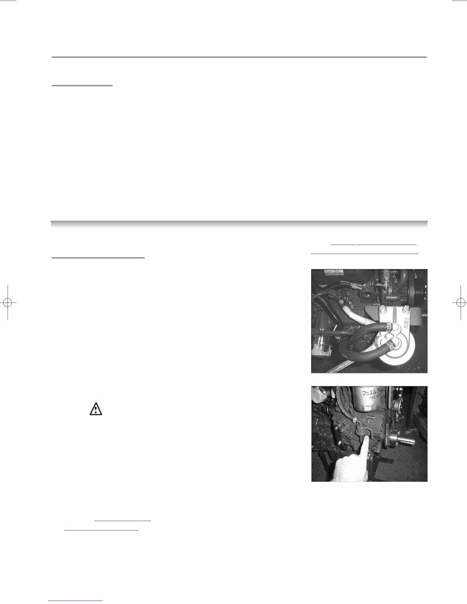
7. Fuel should now be at the fuel lift
pump, see diagram 1a. Open the
sea cock
INITIAL STARTUP AND
BLEEDING THE SYSTEM
(a) Open fuel bleed screw on fuel
filter assembly by 1
1
/ 2 turns. See
diagrams 1a & 1b.
(b) Move hand priming lever on fuel
lift pump up and down until fuel
with no bubbles comes out of the
bleed screw.
(c) Shut/tighten the bleed screw.
Clean area thoroughly with tissue
paper.
(d) Continue to hand prime for 30
seconds to push fuel through the
fuel pump.
(e) Start engine (see normal
starting).
Note the engine may have to be
turned over with the starter for a
few seconds before it fires. Do
not run the starter for more than
20 seconds. If the engine has not
started after 20 seconds then
disengage the starter and
continue to hand prime for a
further 30 seconds, then repeat.
(f) If engine does not start after 3
attempts then allow 5 minutes
for the starter to cool down before
repeating (a) to (e).
Note: The star ter windings can be
burnt out with continuous cranking
Diagram 1a
Diagram 1b
Downloaded from www.Manualslib.com manuals search engine
6
STOPPING
Every propulsion engine is fitted with
a stop solenoid which is energised to
stop. To stop engine simply press
stop push button, hold in until engine
stops, then turn key from ‘RUN’ to
‘OFF’ position.
When leaving the boat for an
extended period,
• Turn off sea-cock (heat exchanger
cooled engines).
• Turn off battery isolator.
Do not turn the key to the off
position when the engine is
running. This will damage the
alternator.
*WARNING
Do not leave the key in ‘HEAT’
position for more than 15 seconds -
this will damage the heater plugs
and eventually lead to poor starting.
Do not depress stop button for more
than 10 seconds as this will lead to
overheating and failure of the
solenoid.
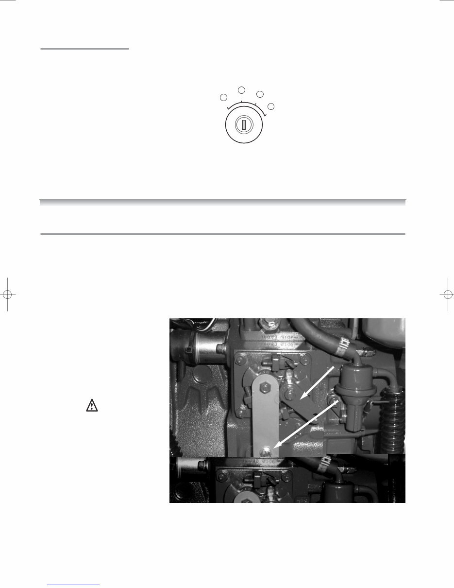
The Super 5 range of engines are
equipped with a mechanical stop
lever in the event of electrical system
failure. This lever is located on the
starboard side of the engine above
the speed control lever. See Fig 2e:
Stop lever
Speed lever
NORMAL STARTING (BETA
PANELS WITH SILVER KEYSWITCH,
FOR KEYLESS SEE PAGE 23)
With the engine out of gear, set speed
control lever to 1/3 throttle. Turn key anti-
clockwise to HEAT* (A) position and hold
for ten seconds, turn key clockwise to
RUN (C) position. At this stage the
instrument panel should illuminate, an
alarm buzzer will sound and two (or
three*) red warning lights will illuminate:
STARTER BATTERY CHARGE
DOMESTIC BATTERY CHARGE (D in
battery symbol - AB & C Deluxe
panels only)
*(Note: this will only illuminate if
2nd alternator is fitted)
OIL PRESSURE
and green POWER ON / RUN LIGHT
(this will stay on)
Turn to START (D) position and engine
will motor, hold in position until
engine fires (see initial start-up section
for maximum
time starter can
be used).
Release key
(when engine
has started) to
RUN position.
Ensure alarm
buzzer is not sounding and that
warning lights are extinguished. If one
or both of the alternator warning lights
are still on, then increase engine
speed to excite the alternator - then
return to idle. The battery charge
lights should then go out. The run
light will remain on (green lamp).
Check for sea water flow. If no flow
then SWITCH OFF IMMEDIATELY
AND CHECK SEA WATER SYSTEM.
Note: for some deluxe panel with the
black keyswitch, they operate
clockwise as legend on panel (OFF –
RUN – HEAT – START). Operation for
engine start procedure is the same as
standard apart from this.
RUN
C
START
D
OFF
B
HEAT
A
Fig. 2e
Downloaded from www.Manualslib.com manuals search engine

7
SECTION 2
MAINTENANCE SCHEDULE
DAILY OR EVERY 8 HOURS
RUNNING
• Check engine oil level.
• Check gearbox oil level.
• Check coolant level.
• Check battery fluid.
• Check drive belt tension
• Ensure raw water inlet strainer is
clear.
• Check stern gland lubrication.
• Drain off any water in fuel water
separator.
AFTER THE FIRST 25 HOURS
RUNNING
• Change gearbox lubricant (See
separate gearbox manual).
• Check that all external nuts,
bolts and fastenings are tight.
See table for torque values.
Special attention should be paid
to the flexible mount lock nuts,
these should be checked for
tightness, starting with lower nut
first in each case. If the lower
nuts are found to be very loose,
then the alignment of the shaft
to the gearbox half coupling
should be re-checked. Poor
alignment due to loose flexible
mount nuts will cause excessive
vibration and knocking.
• Check the belt tension on any
second alternators fitted and
adjust –see page 12.
• Check ball joint nyloc nuts for
tightness on both gearbox and
speed control levers. Grease
both fittings all over.
AFTER FIRST 50 HOURS
• Change engine lubricating oil.
• Change oil filter.
• Check for leaks on header tank
tubestack. Tighten end cap bolt
if required.
• Drain off any water in fuel/water
separator.
EVERY 150 HOURS
• If shallow sump (option) is
fitted, change engine lubricating
oil and filter.
EVERY YEAR – OR EVERY 250
HOURS IF SOONER
• Change engine lubricating oil
(standard sump)
• Change lubricating oil filter
• Check air cleaner element
• Check sea water pump impeller
and change if worn.
• Check wasting anode condition,
replace when necessary. In
some environments this may be
6 montly or less.
• Remove heat exchanger tube
stack, by undoing the bolt each
end of the tube stack. Remove
end cover, pull out tube stack
and clean. Replace rubber ‘O’
rings and re-assemble.
Immediately engine is started
check for leaks.
• Spray the key switch with
WD40 or equivalent to lubricate
the barrel.
• Check that all external nuts,
bolts and fastenings are tight.
See table for torque values.
• Check ball joint nyloc nuts for
tightness on both gearbox and
speed control levers. Grease
both fittings all over.
EVERY 750 HOURS – As every
250 hours plus the following:-
• Change air cleaner element.
• Change fuel filter.
• Change antifreeze.
• Change gearbox oil.
• Check electrical equipment,
condition of hoses and belts,
replace as necessary.
Downloaded from www.Manualslib.com manuals search engine
LUBRICATION
8
Engine oil: Engine oil should be MIL-
L-2104C or have properties of API
classification CC/CD/CE grades. The
following table gives grades of oil
required for various ambient
temperatures.
Note: A good quality 15W/40
mineral or multigrade oil as used in
most diesel car engines will meet
these requirements. Do not use
‘Turbo Diesel Oil’ or additives.
CHECKING ENGINE OIL
LEVEL
For quantities of oil required see
section marked ‘Technical
Specification’, Page 4
When checking the engine oil level,
do so before starting, or more than
five minutes after stopping.
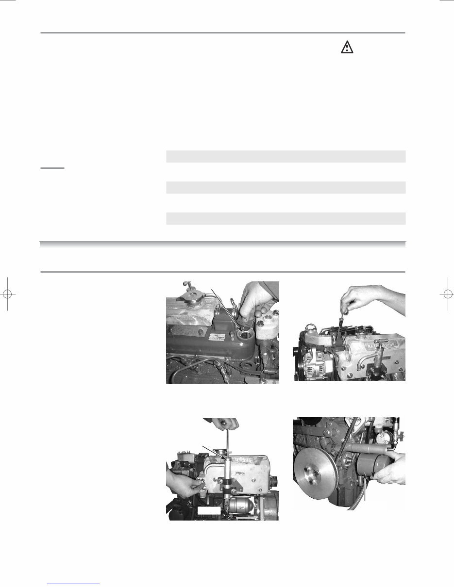
1. To check the oil level, draw out
the dipstick, wipe it clean, re-
insert it, and draw it out again.
Check to see that the oil level lies
between the two notches.
2. If the level is too low, add new oil
to the specified level - Do not
overfill.
IMPORTANT
When using an oil of different make
or viscosity from the previous one,
drain old oil. Never mix two different
types of oil. Engine oil should be
changed after first 50 hours running
time and then every year or every
250 hours if sooner. Oil filter is a
cartridge type mounted on the port
side of the engine.
(1) Run the engine for 10 minutes to
warm up the oil.
(2) Your engine is provided with a
sump drain pump. Unscrew the
end cap on the end of the pump,
turn the tap to ‘on’. Use the hand
pump as shown to pump out the
oil into a bucket. Turn the tap to
off position and replace end cap.
See diagram 2c.
(3) Unscrew the oil filter and replace
with a new one. See diagram 2d.
Note: It is best to have a plastic
bag wrapped round the filter to
catch any oil left in the system.
(Always keep your bilges clean!)
Before screwing in the new filter
spread a thin film of oil round the
rubber gasket to ensure a good
seal and screw in – hand tight.
(4) Fill the engine with new oil as
described above.
(5) Run the engine and check for oil
leaks
AMBIENT TEMP SINGLE GRADE MULTI GRADE
-30°C TO 0°C SAE 10W SAE 10W/30
-15°C TO +15°C SAE 20W SAE 15W/40
0°C TO +30°C SAE 30 SAE 15W/40
25°C AND ABOVE SAE 30 SAE 15W/40
CHANGING ENGINE OIL
Fig. 2d
Oil filter
Fig. 2b. Dip stick
Fig. 2a
Sump
pump
Oil goes
in here
End Cap
Fig. 2c
Downloaded from www.Manualslib.com manuals search engine
You're Reading a Preview
What's Included?
 Lifetime Access
Fast Download Speeds
Online & Offline Access
Access PDF Contents & Bookmarks
Full Search Facility
Print one or all pages of your manual
$28.99
Beta Marine BD1005, BV1305 & BV105 Service Owners Manual
Viewed 88 Times Today

What's Included?
Lifetime Access
Fast Download Speeds
Online & Offline Access
Access PDF Contents & Bookmarks
Full Search Facility
Print one or all pages of your manual
$28.99

Secure transaction
What's Included?
Lifetime Access
Fast Download Speeds
Online & Offline Access
Access PDF Contents & Bookmarks
Full Search Facility
Print one or all pages of your manual
Description
Beta Marine Service Owners Manual
Heat Exchanger Cooled
Small Diesel Engine Range: BD1005, BV1305, and BV1505
- Engine identification
- Initial receipt of the engine
- Engine storage
SAFETY PRECAUTIONS
TECHNICAL SPECIFICATIONS
GUIDELINES FOR OPERATION OF ENGINE
- Important checks prior to initial use
- Initial start-up and bleeding the fuel system
- Starting/stopping
MAINTENANCE SCHEDULE
- Lubrication checking and changing oil
- Fuel system - pumps, filter, fuel/water separator
- Cooling - fresh water system, keel cooling, heat exchanger
- Sea water pump, heat exchanger
- Belt tensioning
- Air filter
- Electrical
- Laying up - winterising
- Troubleshooting
- Torque settings
INSTALLATION GUIDELINES
- Engine mounting
- Alignment - drives, flanges, flexible drives
- Exhausts & mounting exhausts
- Fuel supply
- Cooling - sea water inlet system
- Calorifier system
- Electrical and installations
Appendices wiring diagrams and general arrangements
Component identification at rear of manual
Maintenance record


