Important Information Important Information Particularly important information is distinguished in this manual by the following notations: The Safety Alert Symbol means ATTENTION! BECOME ALERT! YOUR SAFETY IS INVOLVED! A WARNING indicates a hazardous situation which, if not avoided, could result in death or serious injury. A NOTICE indicates special precautions that must be taken to avoid damages to the outboard motor, watercraft, or other property. TIP A TIP provides key information to make procedures easier or clearer.
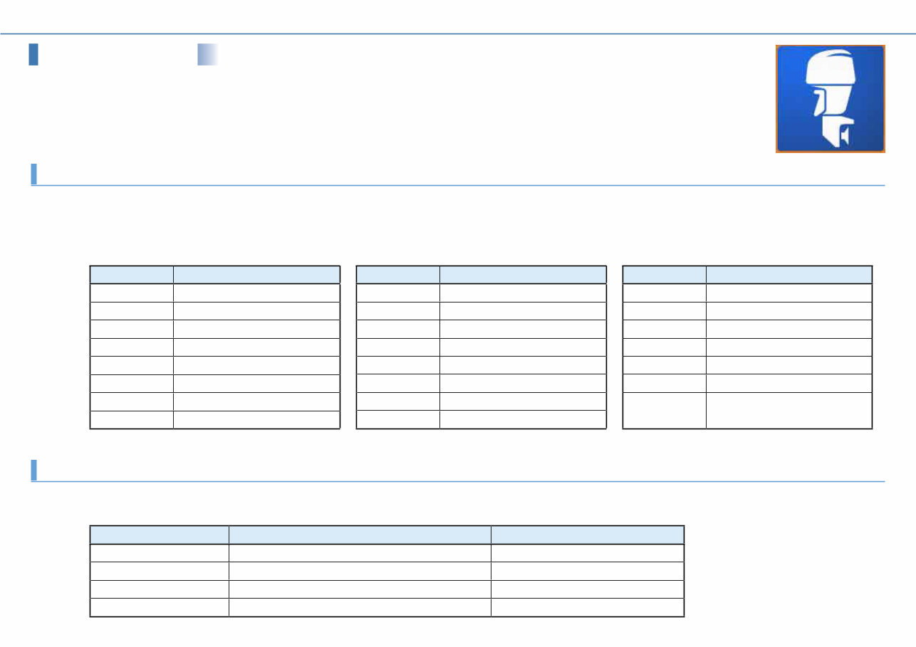
Outboard Motors Outboard Motors Abbreviation The following abbreviations are used in this Instruction Manual and on the YAMAHA Diagnostic System screen. While not included in this table, some names displayed on the YAMAHA Diagnostic System screen have a restriction on the numbers of characters, and are therefore abbreviated. Abbreviation Abbreviation Description APS Accelerator Position Sensor C Center ECM Electronic Control Module ETV Electronic Throttle Valve EX Exhaust F Forward IDM Ionic current Detection Module IN Intake Abbreviation Description ISC Idle Speed Control LPS Lever Position Sensor N Neutral OCV Oil Control Valve P Port side PORT Port side PTT Power Trim and Tilt R Reverse Abbreviation Description S Starboard side SPS Shift Position Sensor STBD Starboard side TPS Throttle Position Sensor VCT Variable Camshaft Timing YDIS YAMAHA Diagnostic System R/C Remote Control (Digital Electronic Control) Product names for each market The following names are used in each market. Meter names for each market North America Worldwide 6Y8 Meter Command Link Multifunction Meter 6Y8 Multifunction Meter 6Y9 Color Gauge Command Link Plus Multifunction Color Gauge 6Y9 Multifunction Color Gauge 6Y8 Meter system Command Link Digital Network (6Y8 Meter) 6Y9 Color Gauge system Command Link Plus Digital Network (6Y9 Color Gauge)
Contents Contents Introduction .................................................................................................. 1 1. Features........................................................................................... 1 1-1. Functions by data transmission type ................................................. 2 1-2. Transmission Method ........................................................................ 4 CAN-Line ■ ................................................................................... 4 K-Line ■ ........................................................................................ 6 1-3. Newly added functions...................................................................... 7 Input Setting ■ ............................................................................... 7 Logging ■ ...................................................................................... 8 CAN Information ■ ........................................................................ 11 2. Compositions of the tool ................................................................. 12 3. Hardware requirements .................................................................. 13 4. Compatible models ......................................................................... 15 5. Languages ..................................................................................... 16 Installation .................................................................................................. 17 1. Before installation ........................................................................... 17 2. Installing the YAMAHA Diagnostic System ....................................... 18 Connecting the computer to the outboard motor ................................... 25 1. Basic connections .......................................................................... 26 2. When logging ................................................................................. 27 3. When viewing input values using external devices ........................... 28 Starting the YAMAHA Diagnostic System ................................................ 30 Quitting the YAMAHA Diagnostic System ................................................ 31 Screen specifications ................................................................................ 32 1. Standard screen ............................................................................. 32 1-1. Title area ........................................................................................ 32 1-2. Status area .................................................................................... 33 1-3. Main area ....................................................................................... 33 1-4. Button area .................................................................................... 34 2. Sub screen..................................................................................... 34 Common operations .................................................................................. 35 1. Selecting the display items .............................................................. 35 1-1. Display items .................................................................................. 35 1-2. Display order .................................................................................. 37 2. Setting the graph properties ............................................................ 38 2-1. Display range ................................................................................. 39 2-2. Display colors ..................................................................................41 3. Saving data .................................................................................... 44 3-1. Data save ...................................................................................... 44 3-2. Data export .................................................................................... 45 4. System Info. button ......................................................................... 46 5. Message button.............................................................................. 47 6. Select Eng. button .......................................................................... 47 7. Back button .................................................................................... 49 Update ......................................................................................................... 50 Setting ......................................................................................................... 52 Engine ......................................................................................................... 53 1. Diagnosis ....................................................................................... 53 1-1. Diagnosis ....................................................................................... 55 1-2. Diagnosis Record ........................................................................... 57 Deleting diagnosis record in the ECM ■ ........................................ 59 1-3. Engine Record ............................................................................... 60 1-4. Engine operating hours ................................................................... 62 2. Engine Monitor ............................................................................... 63 2-1. Digital Display ................................................................................. 64 2-2. Graph Display................................................................................. 65 Saving graph data ■ .................................................................... 66 2-3. Input Setting ................................................................................... 68 3. Component Test ............................................................................. 70 3-1. Stationary Test ............................................................................... 70 Ignition coil activation test ■ ......................................................... 72 Injector activation test ■ ............................................................... 74 Electric fuel pump activation test ■ ............................................... 75 Low-pressure fuel pump activation test ■ ..................................... 76 Oil plunger pump activation test ■ ................................................ 77 ISC valve activation test ■ ........................................................... 79 OCV activation test ■ .................................................................. 80 3-2. Active Test ......................................................................................81 Cylinder drop test ■ ..................................................................... 82 Fully open ISC valve test ■ .......................................................... 83 Fixed ISC valve opening angle test ■ ........................................... 84
Contents 4. Data Logger ................................................................................... 85 4-1. Logger graph.................................................................................. 85 4-2. ECM Record graph......................................................................... 87 4-3. Logging ...........................................................................................91 Clearing data from the adapter ■ ................................................. 92 Record Setting ■ ......................................................................... 93 Displaying data in a graph ■ ......................................................... 96 Boat System................................................................................................ 97 1. Tilt limiter ........................................................................................ 98 Setting the tilt limiter ■ .................................................................. 98 Resetting the tilt limiter setting ■ ..................................................100 2. Digital Electronic Control System .................................................. 103 Resetting the Digital Electronic Control System ■ ........................103 Maintenance.............................................................................................. 105 1. Record of engine oil change ......................................................... 105 CAN Information ....................................................................................... 107 1. Communication List ...................................................................... 107 2. Bus Statistics ................................................................................111 Off-line ....................................................................................................... 113 Appendix ................................................................................................... 115 1. Setting the desktop area............................................................... 115 2. Uninstalling the YAMAHA Diagnostic System................................. 117 3. Troubleshooting ............................................................................ 118 Functions by model (Outboard motor) ................................................... 119
Introduction 1 Introduction The YAMAHA Diagnostic System uses precision fault diagnosis to offer better serviceability at a time when there is increasing demand for service tools for electronically controlled products. It provides quick, reliable, safe, and reasonable service, and is intended to obtain customer satisfaction. The YAMAHA Diagnostic System features updated software and expanded tool functions that allow it to respond to new models and technologies, maintaining compatibility with regulations. Features 1. YAMAHA Diagnostic System Version 2.00 covers most of the functions of the Version 1 series. (Not interchangeable) The CAN-Line transmission method has been added to the conventional transmission method (K-Line), and this enables diagnosis of multiple engines. New functions of Input Settings, Logging, and CAN Information have been added.
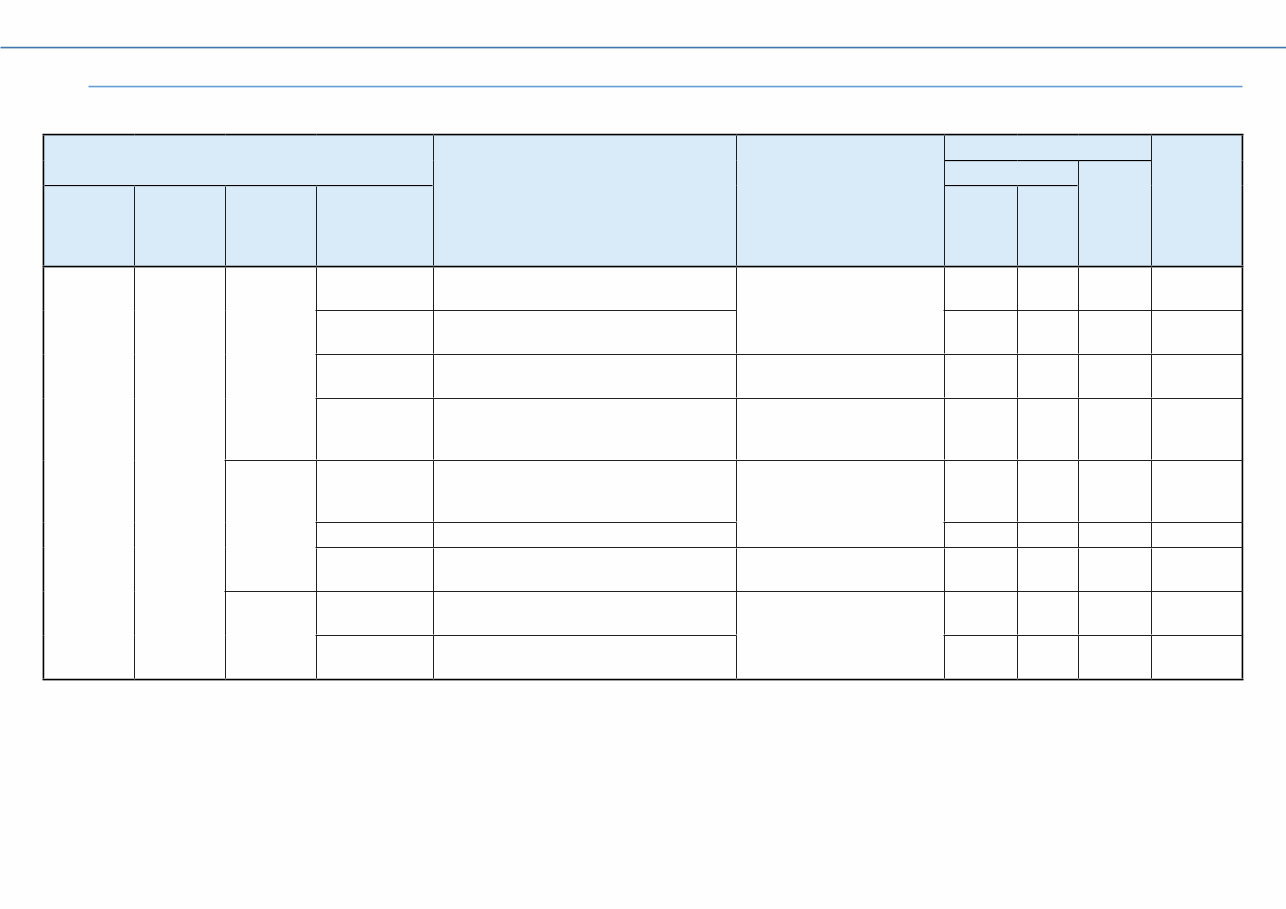
Introduction 2 Functions by data transmission type 1-1. Composition and function-specific characteristics of YAMAHA Diagnostic System Version 2.00 are as per the list below. Menu Primary Function What You Can Do Transmission Method Comparison to Version 1.33 CAN-Line K-Line Top Menu Main Menu 2nd-level Menu 3rd-level Menu 6Y9 Color Gauge hub 6Y8 Meter hub Start Engine Diagnosis Diagnosis Displays results of current fault diagnosis. Identify abnormalities. YES(*1) — YES Diagnosis Record Displays a history of fault diagnosis recorded in the ECM. YES(*1) — YES Engine Record Displays the engine state recorded in the ECM. Check the engine trouble history. YES(*1) — YES Engine operating hours by RPM Displays operating hours by RPM. Check the history of engine usage. YES(*1) — YES Engine Monitor Digital Display Displays ECM data numerically. Check the current operating state of the engine. YES(*1) — YES Graph Display Displays ECM data in graph form. YES(*1) — YES Input Setting Settings to display data from connected external devices on YDIS screen. View data from external devices on YDIS. YES — YES New Component Test Stationery Test Performs an operational test of each component with the engine stopped. Check functioning of each component. YES — YES Active Test Performs an operational test of each component with the engine running. YES — YES (*1) Items that enable diagnosis for multiple engines.
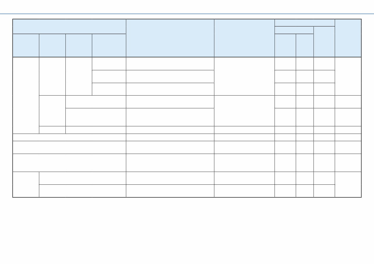
Introduction 3 Menu Primary Function What You Can Do Transmission Method Comparison to Version 1.33 CAN-Line K-Line Top Menu Main Menu 2nd-level Menu 3rd-level Menu 6Y9 Color Gauge hub 6Y8 Meter hub Start Engine Data Logger Record Set Displays a graph of past data recorded in the ECM. Check the past operating state of the engine. YES — YES New Show Data Displays a graph of data recorded before and after troubles. YES — YES Logging Displays a graph of data recorded on the adapter. YES — YES Boat System Tilt Limiter Sets the tilt angle when the outboard motor is tilted up. Configure systems. YES — YES R/C System Reset Returns connection between the outboard motor and the Digital Electronic Control to default settings. YES — YES Maintenance Engine oil change record Records oil change history. Manage oil change history. YES — YES Update Update database. Update database. YES — YES Setting Sets the language and units displayed on YDIS screen. Switch screen displays. YES — YES(*2) New Off Line Displays data saved on the computer, when the ECM is disconnected. Check data saved on computer without connecting to ECM YES — YES CAN Information Communication List Displays quality of CAN system device connection and transmission. Distinguish the type of device connected. YES YES — New Bus Statistics Displays the transmission load ratio for the CAN system. Check whether devices are connected correctly. YES YES — (*2) When connected via K-Line, you cannot select display units.
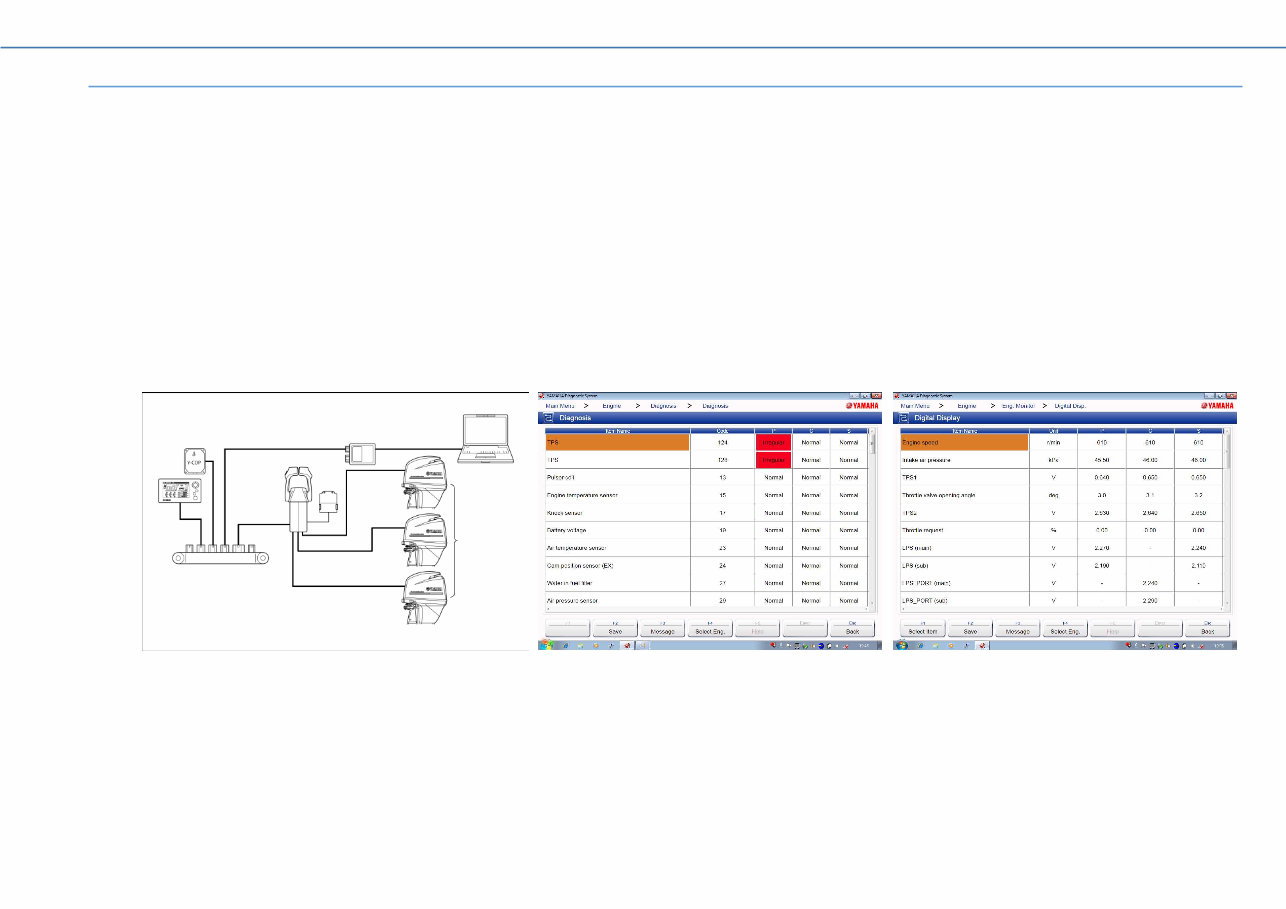
Introduction 4 Transmission Method 1-2. Two transmission methods have been added to YAMAHA Diagnostic System Version 2.00. The CAN-Line in which the transmission harness is connected to a hub, and the K-Line, in which a transmission harness is connected to the outboard motor, which is the same as in the YAMAHA Diagnostic System Version 1 series. CAN-Line ■ There are two types of CAN-Line, the 6Y9 Color Gauge system, and the 6Y8 Meter system. By being connected to a computer using a hub, this enables operation of the YAMAHA Diagnostic System from near the driver’s seat, preventing moisture damage to the computer and peripherals. The 6Y9 Color Gauge system enables display of results of diagnosis for multiple engines. The 6Y8 meter system can use only CAN Information functions. 6Y9 Color Gauge system a Computer e 6Y9 Color Gauge b Adapter f Y-COP c Outboard motor g Digital Electronic Control d Hub a b c g d e f
This comprehensive instruction manual is designed for owners of Yamaha Diagnostics YDIS-Ver2.00 and covers all related models such as YDIS-Ver2.00, YDIS-Ver2.01, YDIS-Ver2.02, and YDIS-Ver2.03. It contains step-by-step instructions accompanied by clear diagrams and illustrations, making it valuable for both professional mechanics and DIY enthusiasts.
The manual offers detailed information on the features, functions, and troubleshooting of the Yamaha Diagnostics YDIS-Ver2.00. Additionally, it provides useful tips and tricks to maximize the product's utility. With this manual, users can effectively diagnose and repair their Yamaha Diagnostics YDIS-Ver2.00.
Whether you are a professional mechanic or a DIY enthusiast, this manual serves as an indispensable companion for understanding and maintaining your Yamaha Diagnostics YDIS-Ver2.00. It presents easy-to-follow instructions for each step, enabling quick and efficient diagnosis and repair.
This Yamaha Diagnostics YDIS-Ver2.00 Instruction Manual is available for purchase online and can be instantly downloaded. It is a valuable resource for anyone seeking comprehensive guidance on their Yamaha Diagnostics YDIS-Ver2.00.