E HOW TO USE THIS MANUAL MANUAL FORMAT All of the procedures in this manual are organized in a sequential, step-by-step format. The information has been compiled to provide the mechanic with an easy to read, handy refer- ence that contains comprehensive explanations of all disassembly, repair, assembly, and inspection operations. In this revised format, the condition of a faulty component will precede an arrow symbol and the course of action required will follow the symbol, e.g., ● Bearings Pitting/scratches → Replace. To assist you in finding your way through this manual, the section title and major heading is given at the top of every page. ILLUSTRATIONS The illustrations within this service manual represent all of the designated models. CROSS REFERENCES The cross references have been kept to a minimum. Cross references will direct you to the appropriate section or chapter.
F D ES UTILISATION DU MANUEL FORMAT DU MANUEL Toutes les procédures décrites dans ce manuel sont organisées de manière séquentielle, pas à pas. Les informations ont été rassemblées afin de fournir au mécanicien une référence simple à lire et pratique qui comporte néanmoins toutes les explications nécessaires au démon- tage, à la réparation, au montage et à l’inspection. Dans cette forme revue, l’état d’un com- posant défectueux précédera une flèche symbolisée et la procédure à mettre e oeuvre suivra le symbole, par ex, ● Roulements Corrosion/endommagement → Remplacer. Pour vous orienter dans ce manuel, le Titre de section et le Principal intitulé sont indiqués sur chaque page. ILLUSTRATIONS Les illustrations dans ce manuel d’entre- tien représentent tous les modèles dési- gnés. REFERENCES Elles ont été réduites au minimum. Elles vous renvoient à la partie ou au chapitre approprié. ZUR VERWENDUNG DIESES HANDBUCHS AUFBAU Alle Verfahren in diesem Hand- buch sind in logischer Reihenfolge Schritt für Schritt erklärt. Es sollte auf diese Weise ein leicht zu lesen- des, bequem zu handhabendes Referenzmaterial geboten wer- den, in dem alle Demontagen, Reparaturen, Zusammenbau- und Inspektionsarbeiten ausführlich beschrieben sind. In dieser abgeänderten Form erscheint nach dem möglicher- weise fehlerhaften Zustand eines Teils ein Pfeil und die erforderliche Gegenmaßnahme. Bsp: ● Lager Lochfraß/Beschädigung → Ersetzen. Um das Auffinden von gewünsch- ten Stellen im Handbuch zu erleichtern, steht oben auf jeder Seite der Titel des Kapitels und des Abschnitts. ILLUSTRATIONEN Die Illustrationen in diesem War- tungshandbuch beziehen sich auf alle bezeichneten Modelle. QUERVERWEISE Querverweise sind auf ein Mini- mum beschränkt worden und ver- weisen auf die betreffenden Abschnitte oder Kapitel. COMO UTILIZAR ESTE MANUAL FORMATO DEL MANUAL Todos los procedimientos de este manual se han preparado de forma secuencial, paso a paso. La información ha sido compilada con el fin de ofrecer al mecá- nico una referencia útil y de fácil lectura que contiene amplias explicaciones de todas las operaciones de desmontaje, reparación, montaje e inspección. En este formato revisado, la condición de un componente averiado irá precedida de un símbolo de flecha y el curso de la acción requerida seguirá al símbolo, por ejemplo: ● Cojinetes Picado/daños → Reemplazar. Para ayudarle a orientarse a través de este manual, en la parte superior de cada página figuran el título de la sección y el encabezamiento principal. ILUSTRACIONES Las ilustraciones de este manual de ser- vicio corresponden a todos los modelos mencionados. REFERENCIAS Las referencias se han reducido al mínimo. Éstas le remitirán directamente a la sección o al capítulo correspon- diente.
E IMPORTANT INFORMATION In this Service Manual particularly important information is distinguished in the following ways. The Safety Alert Symbol means ATTENTION! BECOME ALERT! YOUR SAFETY IS INVOLVED! WARNING Failure to follow WARNING instructions could result in severe injury or death to the machine operator, a bystander, or a person inspecting or repairing the watercraft. CAUTION: A CAUTION indicates special precautions that must be taken to avoid damage to the water- craft. NOTE: A NOTE provides key information to make procedures easier or clearer. IMPORTANT: This part has been subjected to change of specification during production.
F D ES INFORMATIONS IMPORTANTES Les informations particulièrement importantes contenues dans ce manuel d’entretien sont signalées de diverses manières. Le symbole d’alerte sécurité signifie ATTENTION! SOYEZ ATTENTIF! VOTRE SECURITE EST MENA- CEE! AVERTISSEMENT Le non-respect d’une instruction AVERTISSEMENT peut entraîner une blessure ou la mort de l’opéra- teur, d’un passager ou de la personne inspectant ou réparant le scooter nau- tique. ATTENTION: ATTENTION indique les consignes qui doivent être respectées afin d’évi- ter d’endommager le scooter nauti- que. N.B.: N.B. donne des informations importantes qui facilitent et expliquent les différentes opérations. IMPORTANT: Les spécifications de cette partie ont subi des modifications au cours de la produc- tion. WICHTIGE INFORMATIONEN In diesem Wartungshandbuch sind besonders wichtige Informa- tionen auf folgende Weise hervor- gehoben. Dieses Warnsymbol bedeutet: VORSICHT! ES GEHT UM IHRE SICHERHEIT! WARNUNG Eine WARNUNG BEZIEHT SICH AUF eine wichtige Maßnahme, die eingehalten werden muß, um schwerwiegende Verletzungen, möglicherweise sogar mit Todes- folge , für Benutzer, in der Nähe befindliche Personen oder Techni- ker, die Inspektionen oder Repara- turen ausführen, zu vermeiden. ACHTUNG: Die Kennzeichnung ACHTUNG bezeichnet spezielle Verfahren, die befolgt werden müssen, um eine Beschädigung des Wasser- fahrzeugs zu vermeiden. HINWEIS: Ein HINWEIS enthält Informatio- nen, die einen Vorgang einfacher oder deutlicher machen. WICHTIG: Dieser Teil ist während der Pro- duktion verändert worden. DATOS IMPORTANTES Este Manual de servicio contiene datos importantes indicados de la siguiente manera: El símbolo de alerta de seguridad significa ¡ATENCION, ESTA EN JUEGO SU PROPIA SEGURIDAD! ATENCION El incumplimiento de este tipo de ins- trucciones puede causar graves lesio- nes e incluso la muerte , al operador del motor, a las personas a su alrede- dor o al técnico que inspeccione o repare la moto de agua. PRECAUCION: Este tipo de instrucción indica precau- ciones especiales que debe observar para evitar dañar la moto de agua. NOTA: La NOTA proporciona información clave que facilita o clarifica determina- dos procedimientos. IMPORTANTE: Esta pieza ha sido sometida a cambios de especificación durante el proceso de fabricación.
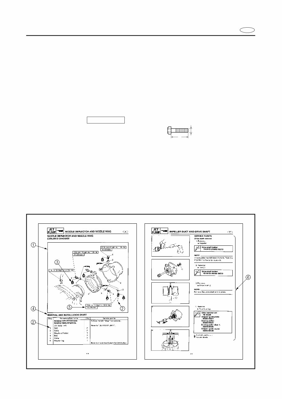
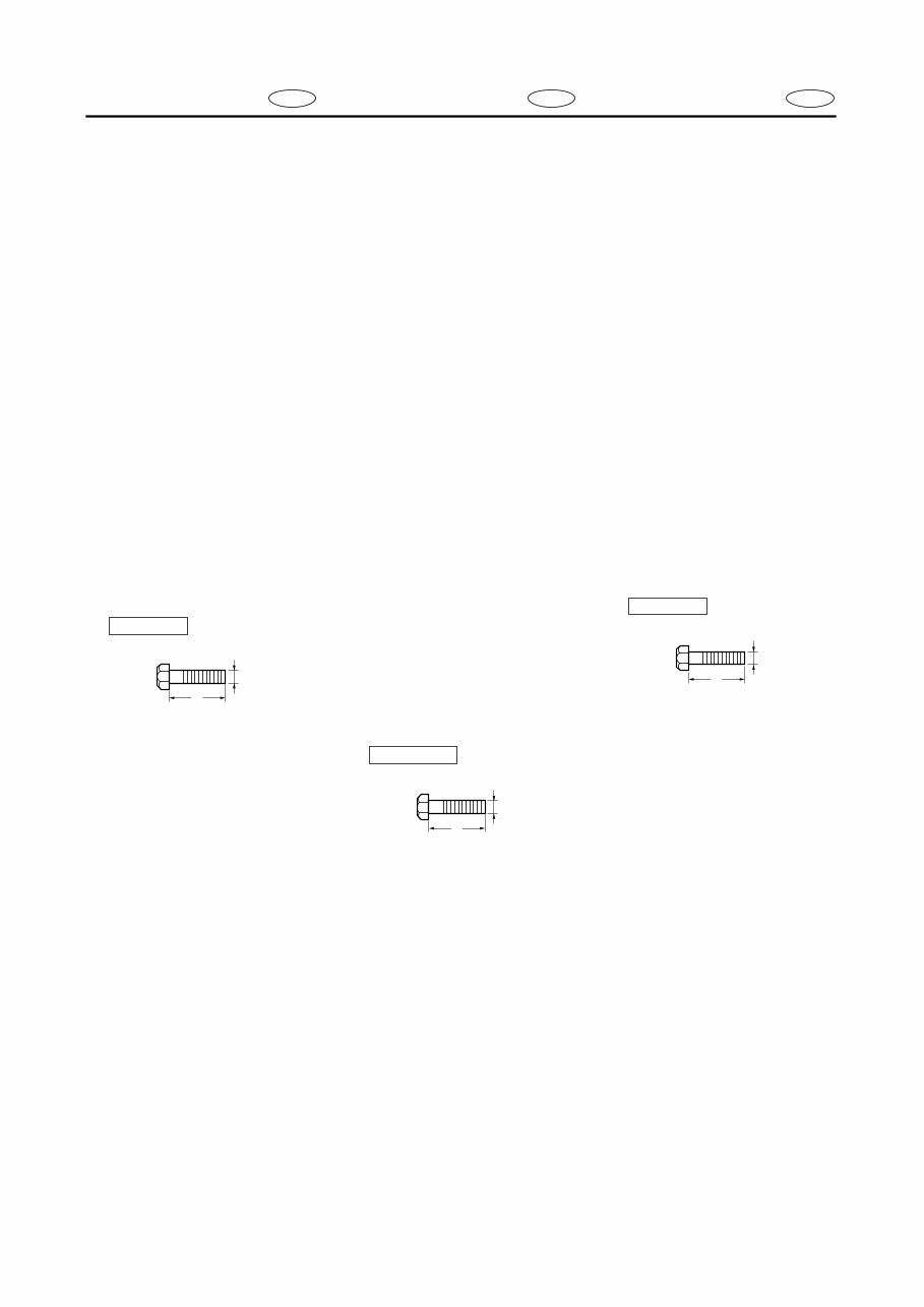
E HOW TO USE THIS MANUAL 1 To help identify parts and clarify procedure steps, there are exploded diagrams at the start of each removal and disassembly section. 2 Numbers are given in the order of the jobs in the exploded diagram. 3 Symbols indicate parts to be lubricated or replaced (see “SYMBOLS”). 4 A job instruction chart accompanies the exploded diagram, providing the order of jobs, names of parts, notes in jobs, etc. 5 Dimension figures and the number of parts, are provided for fasteners that require a tight- ening torque. Example: Bolt or screw size : M10 (D) × 25 mm (L) 6 Jobs requiring more information (such as special tools and technical data) are described sequentially. 10 × 25 mm D L
F D ES UTILISATION DU MANUEL 1 Pour vous aider à identifier les diffé- rentes pièces et à comprendre les diverses étapes opératoires, vous trouverez des vues éclatées au début de chaque partie de dépose et de démontage. 2 Les chiffres sont indiqués dans l’ordre des opérations à effectuer sur le schéma en vue éclatée. 3 Les symboles indiquent les pièces à lubrifier et à remplacer (voir “SYM- BOLES”). 4 Un tableau d’instructions suit la vue éclatée et indique l’ordre des opéra- tions, le nom des pièces, des conseils pratiques, etc. 5 Les dimensions et le numéro des piè- ces sont fournis pour les éléments de fixation qui nécessitent un couple de serrage. Exemple: Taille de boulon ou de vis : M10 (D) × 25 mm (L) 6 Les opérations nécessitant davantage d’explications (indications par exemple d’un outillage spécial ou de données techniques) sont décrites de manière séquentielle. 10 × 25 mm D L VERWENDUNG DIESES HANDBUCHES 1 Um Teile leichter identifizieren und Verfahrensschritte klarstel- len zu können, gibt es am Beginn eines jeden Ausbau- und Demontageabschnitts Explosionszeichnungen. 2 Die Nummern entsprechen der Reihenfolge der Arbeits- schritte in der Explosionszeich- nung. 3 Symbole weisen auf Teile hin, die geschmiert oder ersetzt werden müssen. (siehe “SYM- BOLE”). 4 Zur Explosionszeichnung gibt es eine Arbeitsschritt-Tabelle in der die Reihenfolge der Arbeitsschritte, Bezeichnung der Teile und Hinweise zu den Arbeitsschritten usw. aufge- führt werden. 5 Größenbezeichnungen und Teilenummern werden für Ver- bindungselemente aufgeführt, die ein Anzugsdrehmoment benötigen. Beispiel: Schraubengröße : M10 (D) × 25 mm (L) 6 Arbeitsschritte, die mehr Infor- mationen benötigen (wie z. B. Spezialwerkzeuge und techni- sche Daten), werden der Reihe nach beschrieben. 10 × 25 mm D L COMO UTILIZAR ESTE MANUAL 1 Este manual incluye diagramas deta- llados al comienzo de cada sección de extracción y desmontaje para ayu- darle a identificar las piezas y clarifi- car los pasos de los procedimientos. 2 Los números corresponden al orden de las tareas del diagrama detallado. 3 Los símbolos indican las piezas que deben ser engrasadas o reemplazadas (consultar “SIMBOLOS”). 4 La tabla de las instrucciones de las tareas se adjunta con el diagrama detallado incluyendo el orden de la tarea, los nombres de las piezas, las notas para las tareas, etc. 5 Se proporcionan las cifras de las dimensiones y el número de las pie- zas para las fijaciones que requieran una torsión de apriete. Por ejemplo: Tamaño del perno o del tornillo : M10 (D) × 25 mm (L) 6 Las tareas que requieran mayor información (tales como herramien- tas especiales y datos técnicos) se describen por orden de secuencia. 10 × 25 mm D L
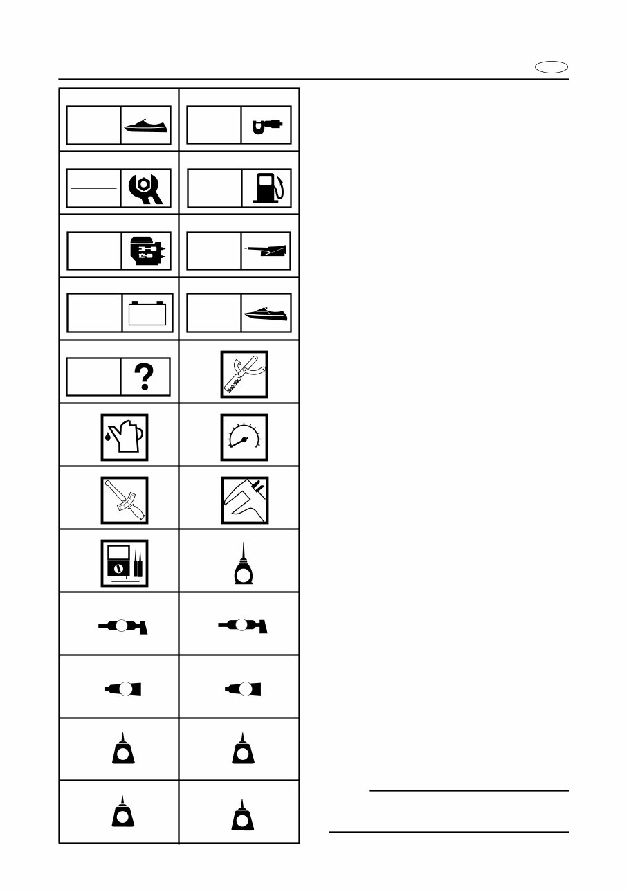
E A50001-1-4 SYMBOLS Symbols 1 to 9 are designed as thumb- tabs to indicate the content of a chapter. 1 General Information 2 Specifications 3 Periodic Inspection and Adjustment 4 Fuel System 5 Power Unit 6 Jet Pump Unit 7 Electrical System 8 Hull and Hood 9 Trouble analysis Symbols 0 to E indicate specific data: 0 Special tool A Specified liquid B Specified engine speed C Specified torque D Specified measurement E Specified electrical value [Resistance (Ω), Voltage (V), Electric current (A)] Symbol F to H in an exploded diagram indicate the grade of lubricant and the loca- tion of lubrication point: F Apply YAMALUBE 2-W oil or TC-W3 cirtified outboard oil G Apply water resistant grease (Yamaha grease A, Yamaha marine grease) H Apply molybdenum disulfide grease Symbols I to N in an exploded diagram indicate the grade of the sealing or locking agent, and the location of the application point: I Apply Gasket Maker ® J Apply Yamabond #4 (Yamaha bond number 4) K Apply LOCTITE ® No. 271 (Red LOCTITE) L Apply LOCTITE ® No. 242 (Blue LOCTITE) M Apply LOCTITE ® No. 572 N Apply silicone sealant NOTE: In this manual, the above symbols may not be used in every case. 1 2 3 4 5 6 7 8 9 0 A B C D E F G H I J K L M N GEN INFO SPEC INSP ADJ FUEL POWR JET PUMP – + ELEC HULL HOOD TRBL ANLS T R . . E A M GM 4 271 LT 242 LT 572 LT LT SS
This service repair manual is an essential resource for servicing or repairing the Yamaha WaveRunner GP800R. It encompasses all repair and maintenance aspects, including the engine, chassis, electrical, fuel system, and drive system. Additionally, the manual features detailed diagrams and illustrations to facilitate the completion of tasks.
The manual covers the following models:
GP800R
GP800
GP800A
GP800R2
This comprehensive service repair manual is indispensable for any Yamaha WaveRunner GP800R owner. It offers detailed, step-by-step instructions for servicing and repairing the WaveRunner, along with accompanying diagrams and illustrations. By utilizing this manual, both professional mechanics and DIY enthusiasts can save time and money on repairs and maintenance, ensuring the smooth operation of their WaveRunner for years to come.
Customers can instantly download this manual through a provided link and make direct online purchases. Acquire your Yamaha WaveRunner GP800R Service Repair Manual today to access all the necessary information for maintaining your WaveRunner in optimal condition.