SYS DIAG 0 1 2 3 4 5 Basic information Installation Troubleshooting Check and adjustment Digital Electronic Control unit System diagram 9 Index BASIC INFO INST DIGIT CONT TRBL SHTG CHK ADJ Contents
BASIC INFO 6X61K12 Basic information 0 Safety while working ..................................................................................... 0-2 Handling of gasoline ................................................................................. 0-2 Ventilation ................................................................................................. 0-2 Self-protection .......................................................................................... 0-2 Part, lubricant, and sealant ....................................................................... 0-2 Handling of sealant ................................................................................... 0-2 Special service tool ................................................................................... 0-3 Tightening torque ...................................................................................... 0-3 Non-reusable part ..................................................................................... 0-3 Disassembly and assembly ...................................................................... 0-3 Working with crane ................................................................................... 0-3 How to use this manual ................................................................................ 0-4 Manual format ........................................................................................... 0-4 Symbol ...................................................................................................... 0-5 Abbreviation .............................................................................................. 0-6 Basic components ........................................................................................ 0-7 Single type ................................................................................................ 0-7 Twin type .................................................................................................. 0-7 Triple type ................................................................................................. 0-7 Model Features .............................................................................................. 0-8 Model ........................................................................................................ 0-8 Serial number ........................................................................................... 0-8 Outline of features ........................................................................................ 0-9 Technical features ....................................................................................... 0-11 Authorization system .............................................................................. 0-13 Shift-in prevention control in high-speed range ...................................... 0-14 Synchronization control .......................................................................... 0-15 PTT control ............................................................................................. 0-16 Tilt limiter ................................................................................................ 0-17 Triple outboard motor operation ............................................................. 0-18 Dual station control (for triple outboard motor installation) ..................... 0-22 Function ....................................................................................................... 0-25 Digital Electronic Control active indicator ............................................... 0-25 Digital Electronic Control alert indicator .................................................. 0-25 Control lever ........................................................................................... 0-26 Free throttle switch ................................................................................. 0-26 PTT switch .............................................................................................. 0-27 Engine selector switch ............................................................................ 0-27 Station selector switch ............................................................................ 0-27 Engine shut-off switch ............................................................................ 0-28 Engine start switch ................................................................................. 0-29 Starter button .......................................................................................... 0-30
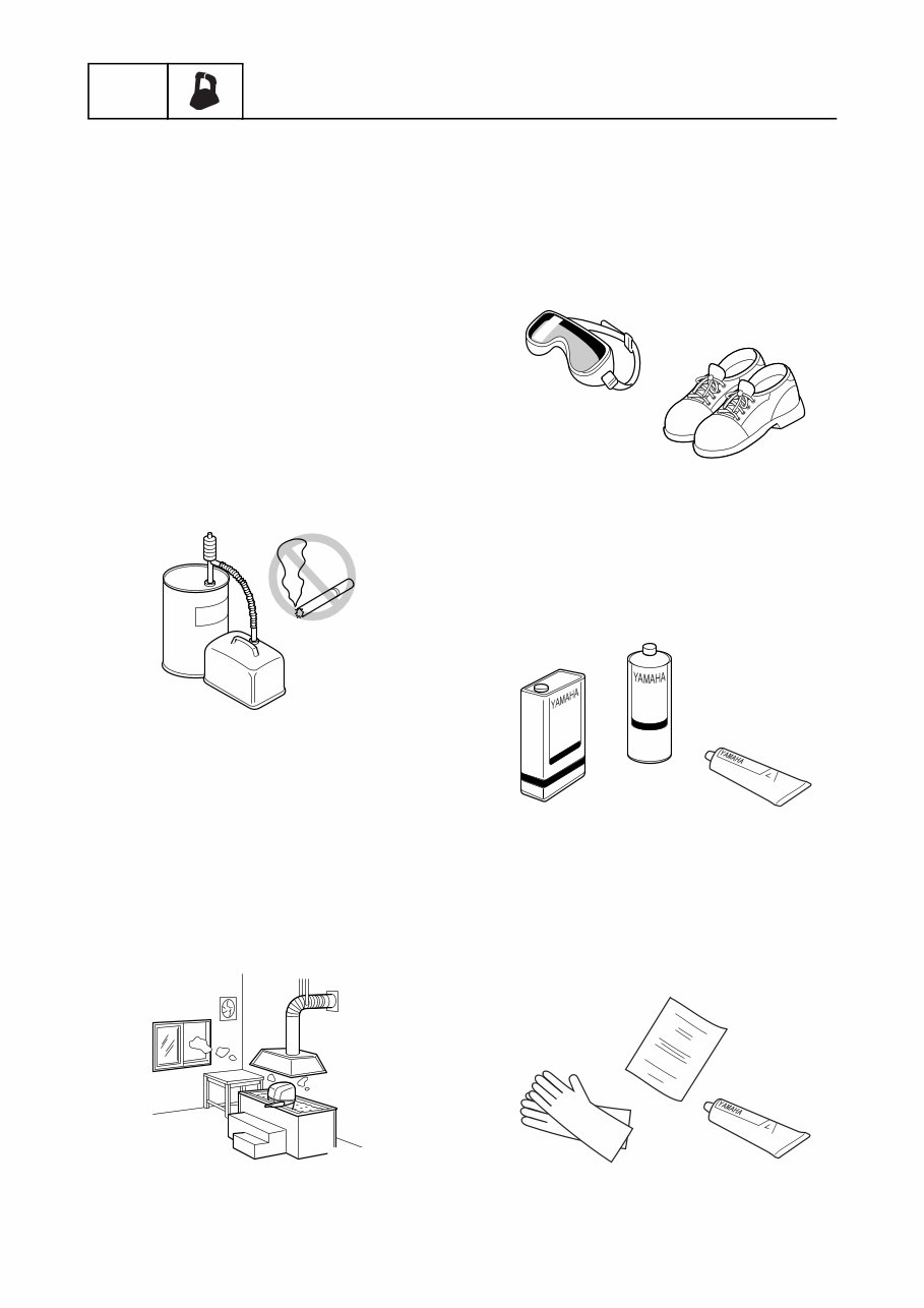
0-2 6X61K12 BASIC INFO Basic information Safety while working To prevent an accident or injury and to ensure quality service, follow the safety pro- cedures provided below. Handling of gasoline • Gasoline is highly flammable. Keep gaso- line and all flammable products away from heat, sparks, and open flames. • Gasoline must be handled with great care. Wash it off with water immediately if your skin or outfit is tainted with gasoline. • If gasoline should get into someone’s eye, wash it off immediately with clean water and see a doctor. • If someone should erroneously swallowed gasoline, see a doctor urgently. Gasoline may cause serious effect on a human body. Ventilation • Gasoline vapor and exhaust gas are heavier than air and extremely poisonous. If inhaled in large quantities they may cause loss of consciousness and death within a short time. • When test running an engine indoors (e.g., in a water tank) be sure to do so where adequate ventilation can be main- tained. Self-protection • Protect your eyes by wearing safety glasses or safety goggles during all opera- tions involving drilling and grinding, or when using an air compressor. • Protect your hands and feet by wearing pro- tective gloves and safety shoes when nec- essary. Part, lubricant, and sealant Use only genuine Yamaha parts, lubricants, and sealants or those recommended by Yamaha, when servicing or repairing the out- board motor. Handling of sealant • Wear protective gloves to protect your skin, when using the sealants. • Refer to the material data sheet issued by the manufacturer. Some of the sealants may be harmful for human health. y0006000i y0006001i y0006002i y0006003i y0006004i
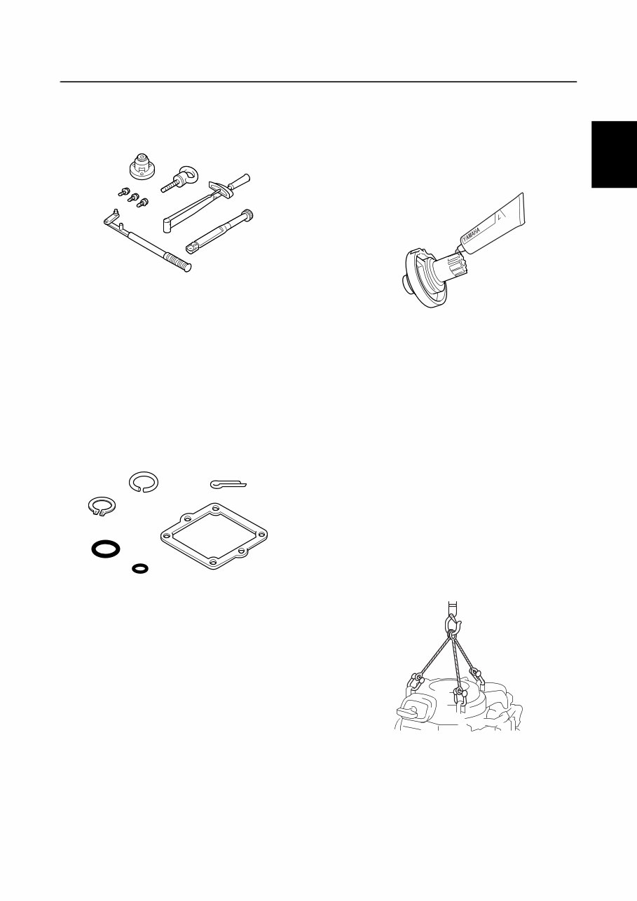
6X61K12 0-3 Safety while working 0 2 3 4 5 6 7 8 9 Special service tool Use the recommended special service tools to protect parts from damage. Use the right tool in the right manner—do not improvise. Tightening torque Follow the tightening torque specifications provided throughout the manual. When tight- ening nuts, bolts, and screws, tighten the large sizes first, and tighten fasteners starting in the center and moving outward. Non-reusable part Always use new gaskets, seals, O-rings, cot- ter pins, circlips, etc., when installing or assembling parts. Disassembly and assembly 1. Use compressed air to remove dust and dirt during disassembly. 2. Apply specified grease to the contact sur- faces of moving parts before assembly. 3. Apply a thin coat of water-resistant grease to the lip and periphery of an oil seal before installation. 4. Check that moving parts operate nor- mally after assembly. Working with crane • Outboard motors weighing 18.0 kg (39.7 lb) and over must be carried by a crane. • Use a wire rope of adequate strength, and lift up the outboard motor with the three point suspension. • If the outboard motor does not have three or more points to be suspended, support it with additional ropes or the like so that the outboard motor can be lifted and carried in a stable manner. y0006005i y0006006i S6X600042 y0006008i
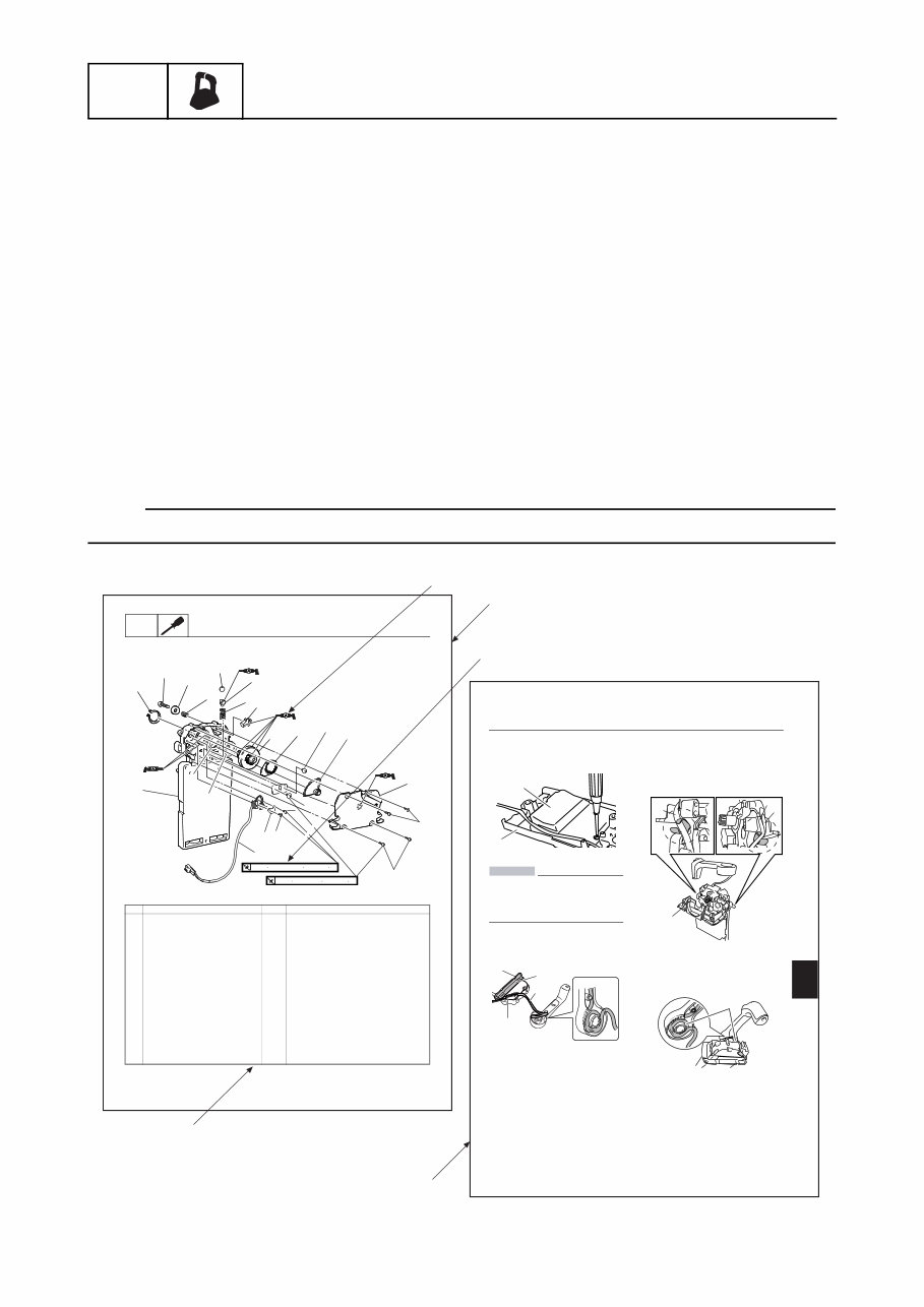
0-4 6X61K12 BASIC INFO Basic information How to use this manual Manual format The format of this manual has been designed to make service procedures clear and easy to under- stand. Use the information below as a guide for effective and quality service. • Parts are shown and detailed in an exploded diagram and are listed in the component list (see a in the figure below for an example page). • The component list consists of part names and quantities, as well as bolt and screw dimensions (see b in the figure below). • Symbols are used to indicate important aspects of a procedure, such as the grade of lubricant and lubrication point (see c in the figure below). • Tightening torque specifications are provided in the exploded diagrams (see d in the figure below for an example), and in the related detailed instructions. Some torque specifications are listed in stages as torque figures or angles in degrees. • Separate procedures and illustrations are used to explain the details of removal, checking, and installation where necessary (see e in the figure below for an example page). NOTE: For troubleshooting procedures, see Chapter 2, “Troubleshooting.” 5-14 Digital Electronic Control disassembly 1 1 3 4 5 5 7 8 9 Assembling the Digital Electronic Control ECM housing 1. Install the Digital Electronic Control ECM b in the housing a. CAUTION: Do not make impact on the Digital Elec- tronic Control ECM in the course of instal- lation. Digital Electronic Control ECM is precision equipment that requires careful handling. 2. Put the PTT switch wiring c into the groove on the rear housing d. 3. Install the stopper plate e (STBD side). 4. Put the neutral switch wiring f and the free throttle switch wiring g through the point a, and put the PTT switch wiring h through the point b on the opposite side. Install the stopper plate i (PORT side) paying attention not to pinch the wirings by the stopper plate i. 5. Install the control lever, and check that the PTT switch wiring f will not be strained while the control lever is moved over the full stroke. a b S6X605023 e c d S6X605024 a b i h h g S6X605025 f S6X605027 5-7 OVER HAUL Overhaul Gear housing No. Part name Q’ty Remarks 1 Digital Electronic Control case assembly 1 2 Neutral switch assembly 1 3 Lock plate 1 4 Screw 2 ø3 x 10mm 5 Screw 4 ø5 x 14mm 6 Rear housing 1 7 Gear 4 8 Screw 2 ø5 x 10mm 9 Drive a rm 1 10 Drive shaft 1 11 Friction plate 1 12 Detent spring 1 13 Detent adapter 1 14 Detent roller 1 15 Spring 1 16 Washer 1 17 Bolt 1 1 2 3 4 4 5 5 6 7 8 8 9 10 11 12 13 14 15 16 17 18 20 19 3.0 N m (0.3 kgf m, 2.2 ft lb) 0.4 N m (0.04 kgf m, 0.3 ft lb) S6X605002-3 a c d b e
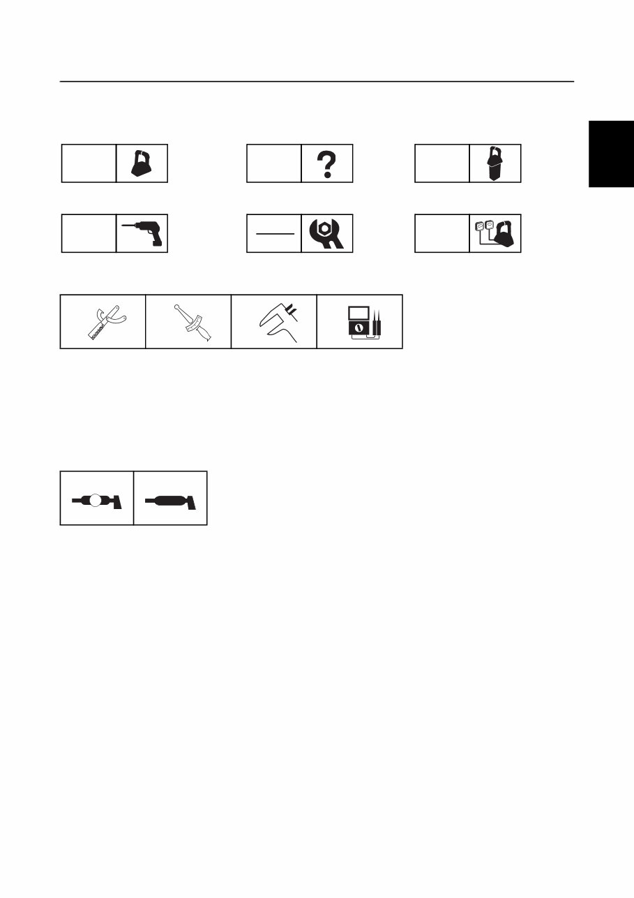
6X61K12 0-5 How to use this manual 0 2 3 4 5 6 7 8 9 Symbol The symbols below are designed to indicate the content of a chapter. Symbols a to d indicate specific data. a Special service tool b Specified tightening torque c Specified measurement d Specified electrical value (resistance, voltage, electric current) Symbols e and f in an exploded diagram indicate the grade of lubricant and the lubrication point. e Apply water resistant grease (Yamaha grease A) f Apply Valvoline X-ALL Basic information BASIC INFO Troubleshooting TRBL SHTG Digital Electronic Control unit DIGIT CONT Installation INST Check and adjustment CHK ADJ System diagram SYS DIAG a T R . . b c d e A f Valvoline X-ALL
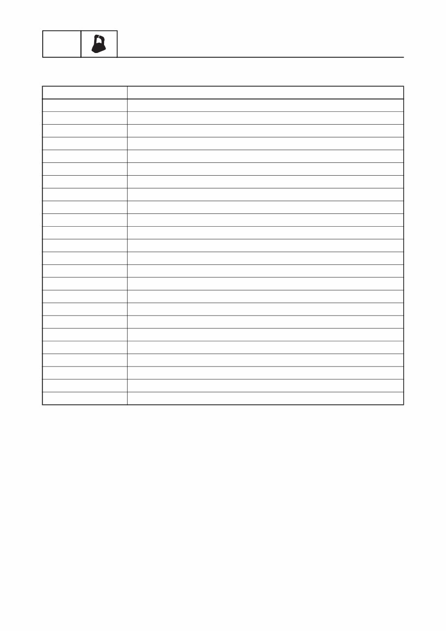
0-6 6X61K12 BASIC INFO Basic information Abbreviation The following abbreviations are used in this service manual. Abbreviation Description DN Down ECM Electronic Control Module ENG Engine ETV Electronic Throttle Valve F Forward GPS Global Positioning System ID Identification INT Intake LAN Local Area Network LPS Lever Position Sensor Max Maximum Min Minimum N Neutral OBM Outboard Motor PDI Pre Delivery Inspection PORT Port side PTT Power Trim and Tilt R Reverse R.C. Remote Control (Digital Electronic Control) SPS Shift Position Sensor STBD Starboard side TPS Throttle Position Sensor WD Wiring Diagram YDIS Yamaha Diagnostic System
A complete collection workshop repair manual is available for the Yamaha Marine COMMAND LINK PLUS. This manual is designed to assist in diagnosing vehicle-related issues and providing recommended repair and maintenance procedures. It is also intended to guide mechanics, including beginners, in disassembly, part inspection, rebuilding, and component assembly.
The Yamaha Marine COMMAND LINK PLUS workshop repair manual is suitable for any vehicle owner and can be utilized by individuals regardless of their profession.
Instant access! No waiting time required. You will receive this manual immediately via email.
Format: .PDF. Compatibility: All operating system versions for devices with a PDF reader.
This collection covers the following topics:
General information
Specifications
Technical features and descriptions
Rigging information
Troubleshooting
Electrical system
Electronic Control Unit
Index
Appendix
The collection includes the following manuals: Yamaha Marine COMMAND Service Manual, Yamaha Marine COMMAND Workshop Manual, Yamaha Marine COMMAND Repair Manual, Yamaha Marine COMMAND Maintenance Manual, Yamaha Marine COMMAND Factory Manual, Yamaha Marine COMMAND Shop Manual, Yamaha Marine COMMAND Technical Manual, Yamaha Marine COMMAND Manual.






 Lifetime Access




