HOW TO USE THIS MANUAL MANUAL FORMAT All of the procedures in this manual are organized in a sequential, step-by-step format. The infor- mation has been compiled to provide the mechanic with an easy-to-read, handy reference that con- tains comprehensive explanations of all disassembly, repair, assembly, and inspection operations. In this revised format, the condition of a faulty component will precede an arrow symbol and the course of action required will follow the symbol, e.g.: ● Bearings Pitting/Damage ➔ Replace. To assist you in finding your way about this manual, the Section Title and Major Heading is given at the head of every page. An index to contents is provided on the first page of each section. THE ILLUSTRATIONS Some illustrations in this manual may differ from the model you have.This is because a procedure described may relate to several models, though only one may be illustrated. (The name of model described will be mentioned in the description.) REFERENCES These have been kept to a minimum, however, when you are referred to another section of the man- ual, you are told the page number. WARNINGS, CAUTIONS AND NOTES Attention is drawn to the various Warnings, Cautions, and Notes which distinguish important infor- mation in this manual in the following ways: The Safety Alert Symbol means ATTENTION! BECOME ALERT! YOUR SAFETY IS INVOLVED! Failure to follow WARNING instructions could result in se vere injur y or death to the machine operator, a bystander, or a person inspecting or repairing the jet boat. A CAUTION indicates special precautions that must be taken to avoid damage to the jet boat. NOTE: ________________________________________________________________________ A NOTE provides key information to make procedures easier or clearer. IMPORTANT: __________________________________________________________________ This part has been subjected to change of specification during production.
HOW TO READ DESCRIPTIONS 1. A disassembly/installation job instruction mainly consists of the exploded diagram 1. 2. The numerical figures represented by the number 2 indicates the order of the job steps. 3. The symbols represented by the number 3 indicates the contents and notes of the job. For the meanings of the symbols, refer to the next page(s). 4. The REMOVAL AND INSTALLATION CHART 4 is attached to the exploded diagram and explains the job steps, part names, notes for the jobs, etc. 5. The SERVICE POINTS, other than the exploded diagram, explains in detail the items difficult to explain in the exploded diagram of REMOVAL AND INSTALLATION CHART, the Service Points requiring the detailed description 5, etc.
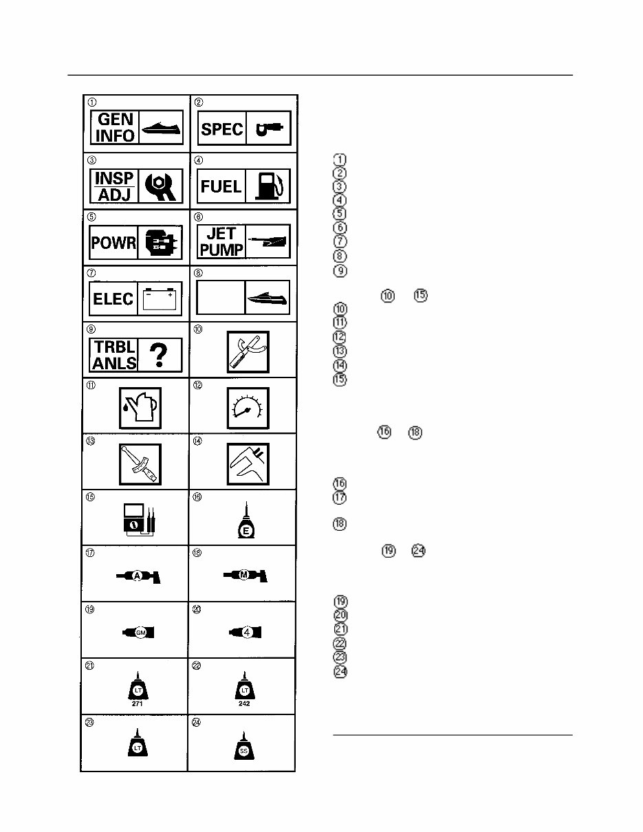
SYMBOLS Symbols 1 to 9 are designed as thumb-tabs to indicate the content of a chapter: General Information Specifications Periodic Inspection and Adjustment Fuel System Power Unit Jet Pump Unit Electrical System Hull and Deck Trouble Analysis Symbols to indicate specific data: Special Tool Specified Liquid Specified Engine Speed Specified Torque Specified Measurement Specified Electrical Value [Resistance (), Voltage (V), Electric Current (A)] Symbol to in an exploded diagram indi- cate grade of lubricant and location of lubrica- tion point: Apply Yamaha 2-stroke outboard motor oil Apply water resistant grease (Yamaha grease A, Yamaha marine grease) Apply molybdenum disulfide grease Symbols to in an exploded diagram indi- cate grade of sealing or locking agent and loca- tion of application point: Apply Gasket Maker® Apply Yamabond #4 (Yamaha Bond No. 4) Apply LOCTITE® No. 271 (Red LOCTITE) Apply LOCTITE® No. 242 (Blue LOCTITE) Apply LOCTITE® No. 567 (PST) Apply Silicone Sealant NOTE: ______________________________ In this manual, the above symbols may not be used in every case. HULL DECK 567
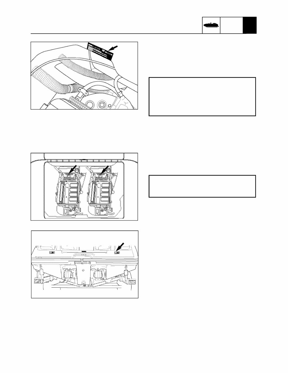
GENERAL INFORMATION x 1 -1- GEN INFO A60700-0* IDENTIFICATION NUMBERS PRIMARY I.D. NUMBER The primary I.D. number is stamped on a label attached to the deck under the rear seat. ENGINE SERIAL NUMBER The engine serial number is stamped on a label attached to the oil tank. HULL IDENTIFICATION NUMBER (H.I.N.) The H.I.N. is stamped into the hull on the star- board side of the stern. Starting Primary I.D. Number: SRT1000D (SR230) F1C-700801~ SRT1000A-D (SX230) F1C-710901~ SRT1000B-D (AR230) F1C-730501~ Starting Engine Serial Number: 6B5: 1008700~
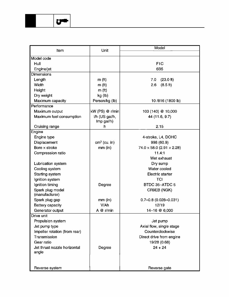
GENERAL SPECIFICATIONS Jet thrust nozzle trim angle Degree +3 Impeller pitch Degree Port 17.3 / Stbd. 16.3 SR/SX: 2.1 (6.92 ft); AR:3.1 (10.3 ft) Exhaust system SRT1000-D, A-D, B-D (on trailer) SR/SX: 1372 (3,025 lb); AR: 1406 (3,100 lb) -2- GENERAL SPECIFICATIONS 2 SPEC
GENERAL SPECIFICATIONSx 2 SPEC SRT1000-D, A-D, B-D -3-
Whether you are a professional mechanic or a DIY enthusiast, this repair manual provides comprehensive troubleshooting and replacement procedures recommended by the manufacturer. It includes step-by-step instructions, clear images, and exploded-view illustrations to assist in fixing problems on your boat.
Regular maintenance is essential for your boat, and over time, certain parts may wear out and require replacement. This manual offers the manufacturer's recommended troubleshooting charts and replacement procedures, enabling you to address issues and ensure minimal downtime.
Featuring every service and repair procedure provided by the manufacturer, this manual eliminates the need to search through numerous pages for specific information. Its digital format allows for easy accessibility, searchability, and portability, making it a convenient alternative to traditional bound manuals.
Additionally, the manual is printable and compatible with various electronic devices, including PC & Mac computers, Android and Apple smartphones & tablets, and more. It requires Adobe Reader for access, and you also have the option to print a physical copy if preferred.