

Repair&ServiceManual
@YAMAHA
275E
275SE
275SD
erviceManual

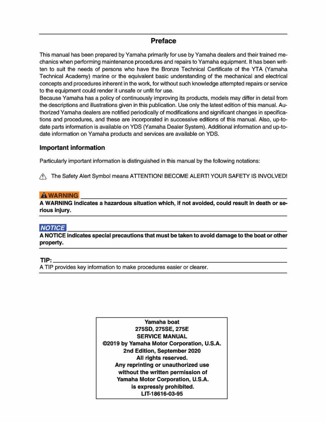
Preface
ThismanualhasbeenpreparedbyYamahaprimarilyforusebyYamahadealersandtheirtrainedme-
chanicswhenperformingmaintenanceproceduresandrepairstoYamahaequipment.Ithasbeenwrit-
tentosuittheneedsofpersonswhohavetheBronzeTechnicalCertificateoftheYTA(Yamaha
TechnicalAcademy)marineortheequivalentbasicunderstandingofthemechanicalandelectrical
conceptsandproceduresinherentinthework,forwithoutsuchknowledgeattemptedrepairsorservice
totheequipmentcouldrenderitunsafeorunfitforuse.
BecauseYamahahasapolicyofcontinuouslyimprovingitsproducts,modelsmaydifferindetailfrom
thedescriptionsandillustrationsgiveninthispublication.Useonlythelatesteditionofthismanual.Au-
thorizedYamahadealersarenotifiedperiodicallyofmodificationsandsignificantchangesinspecifica-
tionsandprocedures,andtheseareincorporatedinsuccessiveeditionsofthismanual.Also,up-to-
datepartsinformationisavailableonYDS(YamahaDealerSystem).Additionalinformationandup-to-
dateinformationonYamahaproductsandservicesareavailableonYDS.
Importantinformation
Particularlyimportantinformationisdistinguishedinthismanualbythefollowingnotations:
QSTheSafetyAlertSymbolmeansATTENTION!BECOMEALERT!YOURSAFETYISINVOLVED!
‘AWARNINGIndicatesahazardoussituationwhich,ifnotavoided,couldresultindeathorse-
riousinjury.
NOTICE
ANOTICEindicatesspecialprecautionsthatmustbetakentoavolddamagetotheboatorother
property.
TIP:
ATIPprovideskeyinformationtomakeprocedureseasier orclearer.
Yamahaboat
275SD,275SE,275E
SERVICEMANUAL
©2019byYamahaMotorCorporation,U.S.A.
2ndEdition,September2020
Allrightsreserved.
Anyreprintingorunauthorizeduse
withoutthewrittenpermissionof
YamahaMotorCorporation,U.S.A.
Isexpresslyprohibited.
LIT-18616-03-95

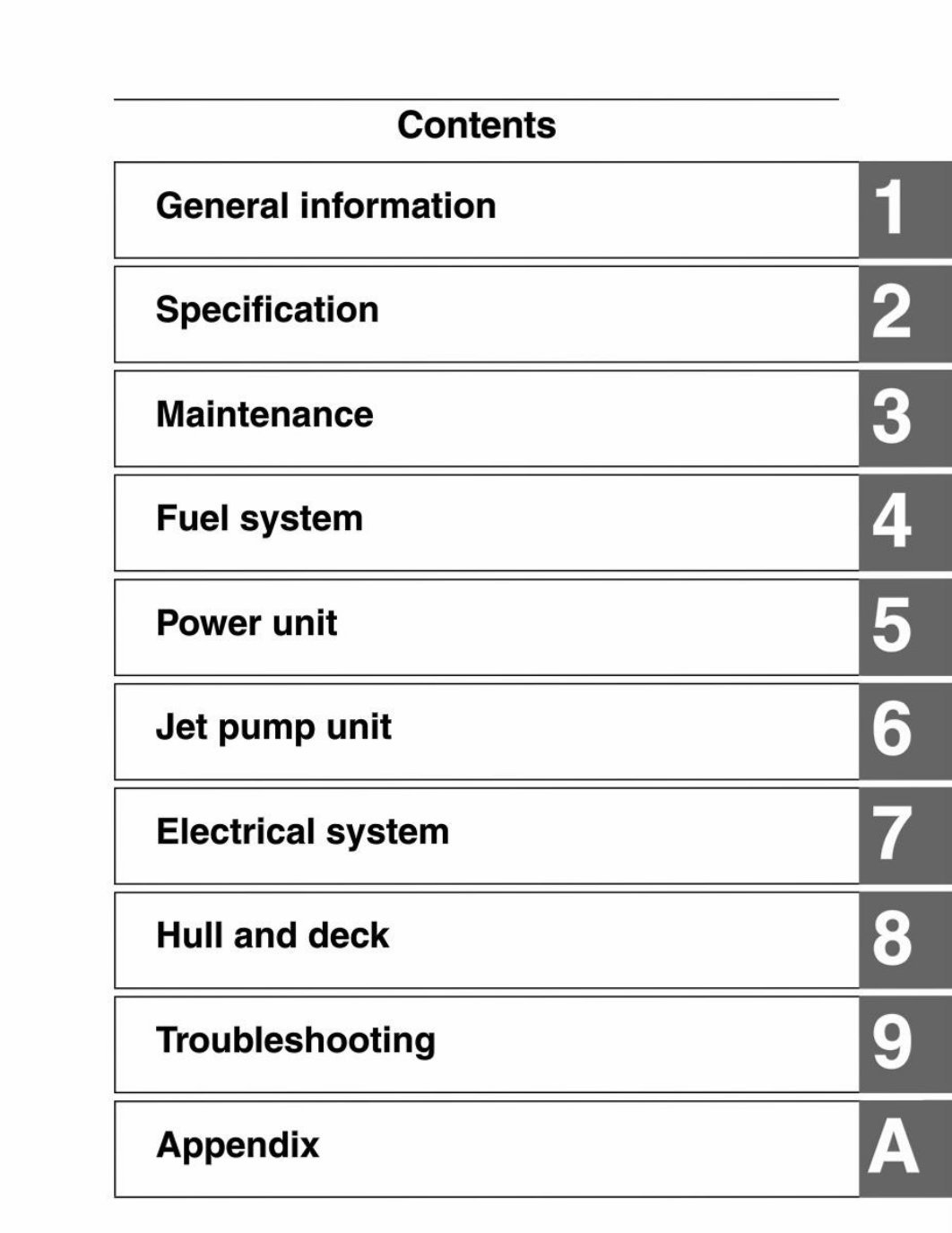
Contents
Generalinformation
Specification
Maintenance
Fuelsystem
Powerunit
Jetpumpunit
Electricalsystem
Hullanddeck
Troubleshooting
Appendix
|] 0} CO] NJ | on] BY] oo/ ro] |

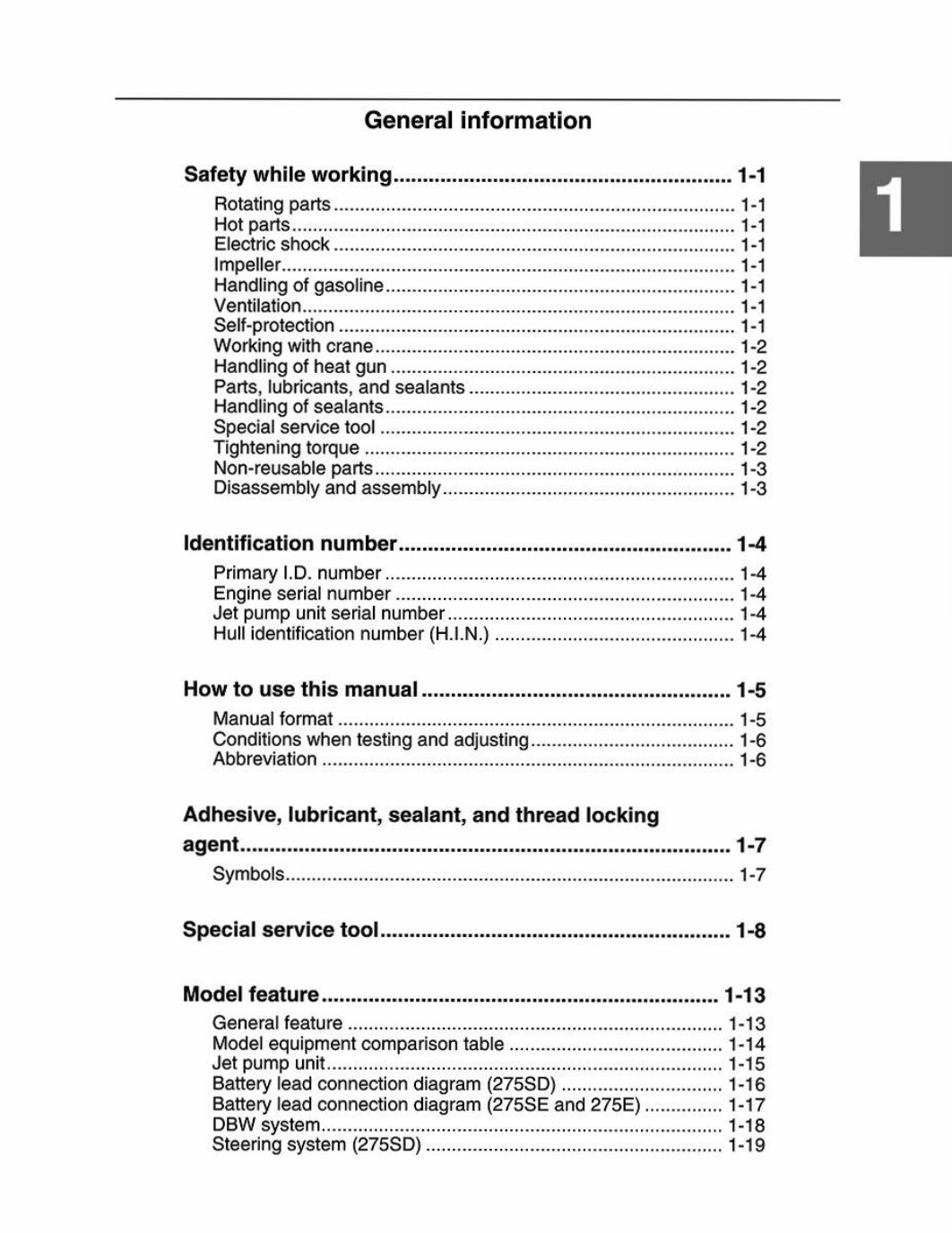
Generalinformation
Safetywhileworking
Rotatingparts
Hotparts...
Electricshock
Impeller...
Handlingofgasoline...
Ventilation...
Self-protectior
Workingwithcrani
Handlingofheatgun
Parts,lubricants,andsealants
Handlingofsealants.
Specialservicetool
Tighteningtorque..
Non-reusableparts
Disassemblyandassembly.
Identificationnumbe:
Primary|.D.number .
Engineserialnumber
Jetpumpunitserialnumber
Hullidentificationnumber(H.I.
Howtousethismanual.....
Manualformat....
Conditionswhentestingandadjusting.
Abbreviation.......
Adhesive,lubricant,sealant,andthreadlocking
agent...
Symbol:
Specialservicetool
Modelfeature..
Generalfeature.
Modelequipmentcomparisontable
Jetpumpunit......
Batteryleadconnectiondiagram(
Batteryleadconnectiondiagram(275SEand275E).
DBWsystem.......
Steeringsystem(275SD)
1-13
-13
-14
-18
-16
“17
-18
-19
Generalinformation
DRIVEmode(275SD)......
Singlelevermode.
Drivecontrolfunction..
Cruiseassistfunction
No-wakemodefunction
ReverseRPMcontrol
Multi-functiondisplaysystem
Controller...
Multi-functiondisplayelements ..
Leftandrightgauges(runningmode)
Leftandrightgauges(floatmode)
Mainscreen..
Screentabbar..
Statusindicatorbar
Homescreen
Mapscreen.
Tripscreen
Drivecontrolscreen
Mediascreen
Systemcontrolscree!
Settingscreen..
Diagnosisscreen...
Warnings OVO YVYOYYOHYOYYYOKYVYYAHNVKVVVNDLSSSSSGGYUVVNSS SSS SONNNS
Technicaltips....
Enginecontrol..
Enginecontrolsystem
Lubricationsystem..
Coolingsystem
Coolingwaterflow
Drainingwaterflow ..1-41
Drivesystemlayout1-42
DBWsystem.1-43
Steeringsystem(275SD)1-44
Replacementpartsandcalibrationtable1-46
Calibration.....1-47
Cableandhoserouting..
Steeringcablesandsteeringhoses(275SD)(topview)
Steeringcables(275SEand275E)(topview)....
Shiftcablesandfuelandbreatherhoses(topview)
Drainhoses(topandstarboardview)....
Coolingwaterandflushinghoses(topview)
Generalinformation
Deckwireharnessrouting............+:00psueadsstbeaniuadescseceess1-64
Bow.
Stern
Enginewireharnessrouting....
Topandportview.
Starboardview..
Rearview...
Electricalboxview
Safetywhileworking
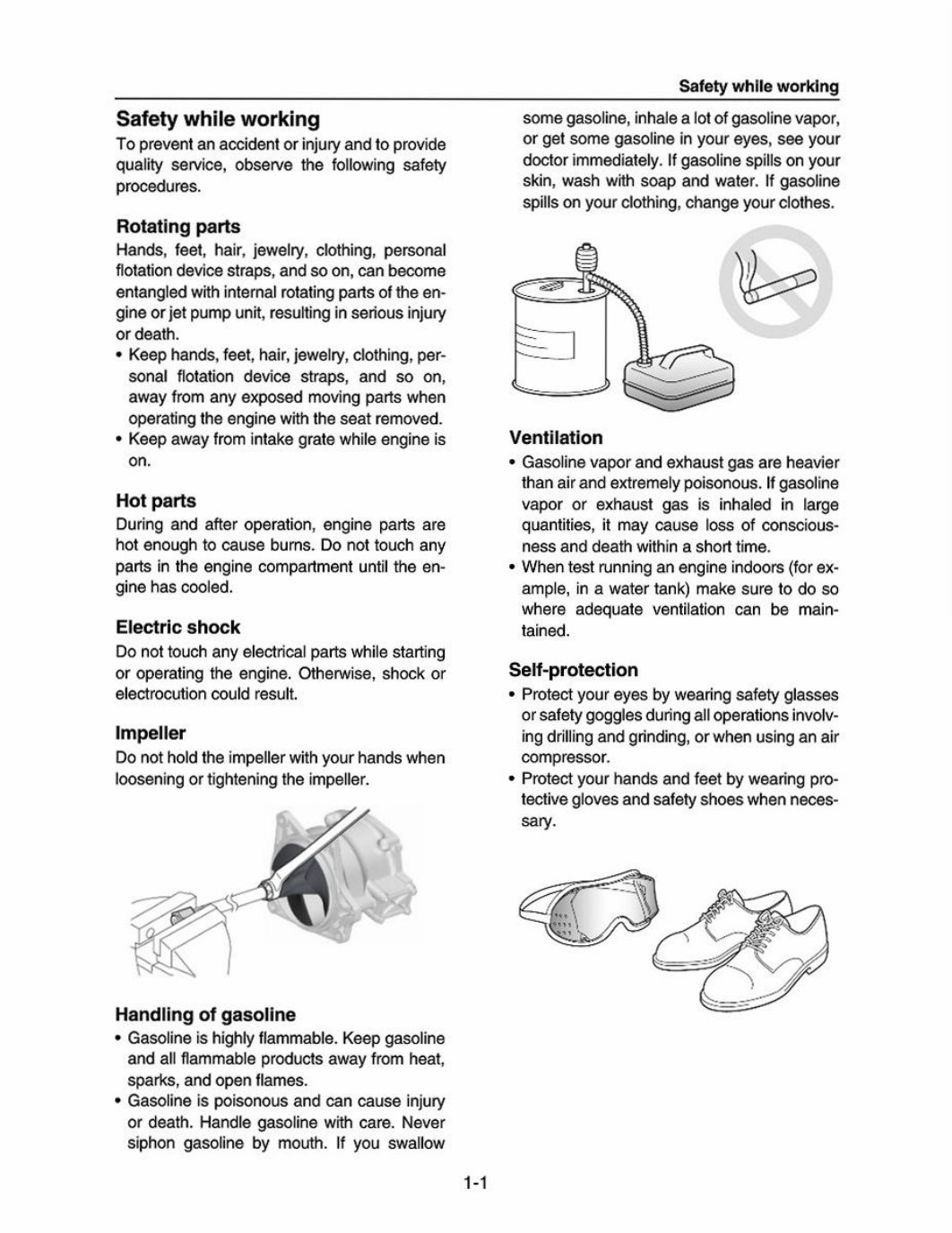
Safetywhileworking
Topreventanaccidentorinjuryandtoprovide
qualityservice,observethefollowingsafety
procedures.
Rotatingparts
Hands,feet,hair,jewelry,clothing,personal
flotationdevicestraps,andsoon,canbecome
entangledwithinternalrotatingpartsoftheen-
gineorjetpumpunit,resultinginseriousinjury
ordeath.
*Keephands,feet,hair,jewelry,clothing,per-
sonalflotationdevicestraps,andsoon,
awayfromanyexposedmovingpartswhen
operatingtheenginewiththeseatremoved.
*Keepawayfromintakegratewhileengineis
on.
Hotparts
Duringandafteroperation,enginepartsare
hotenoughtocauseburns.Donottouchany
partsintheenginecompartmentuntiltheen-
ginehascooled.
Electricshock
Donottouchanyelectricalpartswhilestarting
oroperatingtheengine.Otherwise,shockor
electrocutioncouldresult.
Impeller
Donotholdtheimpellerwithyourhandswhen
looseningortighteningtheimpeller.
\)
Handlingofgasoline
*Gasolineishighlyflammable.Keepgasoline
andallflammableproductsawayfromheat,
sparks,andopenflames.
*Gasolineispoisonousandcancauseinjury
ordeath.Handlegasolinewithcare.Never
siphongasolinebymouth.Ifyouswallow
somegasoline,inhalealotofgasolinevapor,
orgetsomegasolineinyoureyes,seeyour
doctorimmediately.Ifgasolinespillsonyour
skin,washwithsoapandwater.Ifgasoline
spillsonyourclothing,changeyourclothes.
*Gasolinevaporandexhaustgasareheavier
thanairandextremelypoisonous.Ifgasoline
vapororexhaustgasisinhaledinlarge
quantities,itmaycauselossofconscious-
nessanddeathwithinashorttime.
*Whentestrunninganengineindoors(forex-
ample,inawatertank)makesuretodoso
whereadequateventilationcanbemain-
tained.
Self-protection
*Protectyoureyesbywearingsafetyglasses
orsafetygogglesduringalloperationsinvolv-
ingdrillingandgrinding,orwhenusinganair
compressor.
*Protectyourhandsandfeetbywearingpro-
tectiveglovesandsafetyshoeswhenneces-
sary.
You're Reading a Preview
What's Included?
Fast Download Speeds
Online & Offline Access
Access PDF Contents & Bookmarks
Full Search Facility
Print one or all pages of your manual
$57.99
2024 Yamaha 275SE Service & Repair Manual
Viewed 70 Times Today

What's Included?
Fast Download Speeds
Online & Offline Access
Access PDF Contents & Bookmarks
Full Search Facility
Print one or all pages of your manual
$57.99

Secure transaction
What's Included?
Fast Download Speeds
Online & Offline Access
Access PDF Contents & Bookmarks
Full Search Facility
Print one or all pages of your manual
Description
The Yamaha 275SE Service & Repair Manual is a comprehensive guide for both professional mechanics and DIY enthusiasts. This manual provides detailed instructions on troubleshooting, repair, and maintenance procedures to help you understand and address the inner workings of your vehicle.
- A detailed overview of the vehicle's systems, including electrical, mechanical, and hydraulic components
- Step-by-step procedures for diagnosing and resolving common issues
- Troubleshooting guides to help you identify and fix problems efficiently
- In-depth information on maintenance and repair techniques for various components
- Specifications, diagrams, and illustrations to aid in understanding complex systems
This manual is suitable for anyone who needs a technical guide to work on their Yamaha 275SE. Whether you're a seasoned mechanic or a DIY enthusiast, this resource will provide the knowledge and confidence to tackle a wide range of tasks.


