

Tige Faria Pilot Gauge Manual ó Installation and Operation Guide
What's Included?
Fast Download Speeds
Online & Offline Access
Access PDF Contents & Bookmarks
Full Search Facility
Print one or all pages of your manual
Installation and Operation Guide
385 Norwich-New London Turnpike, Uncasville, CT USA 06382-0983 385 Norwich-New London Turnpike, Uncasville, CT USA 06382-0983
Tel: (860)-848-9271 Fax: (860)-848-2704 Customer Service: (800)-473-2742 ext.1229 Tel: (860)-848-9271 Fax: (860)-848-2704 Customer Service: (800)-473-2742 ext.1229
Internet: www.faria-instruments.com e-mail faria@faria-instruments.com
Pilot System
KL
FT
FA
M
DIS
KTS
MPH
S
D

Copyright 2000 by the T G. Faria Corporation
No part of this publication may be reproduced in any form, in an electronic retrieval system or otherwise, without the prior
written permission of the company
KL
FT
FA
M
DIS
KTS
MPH
S
D
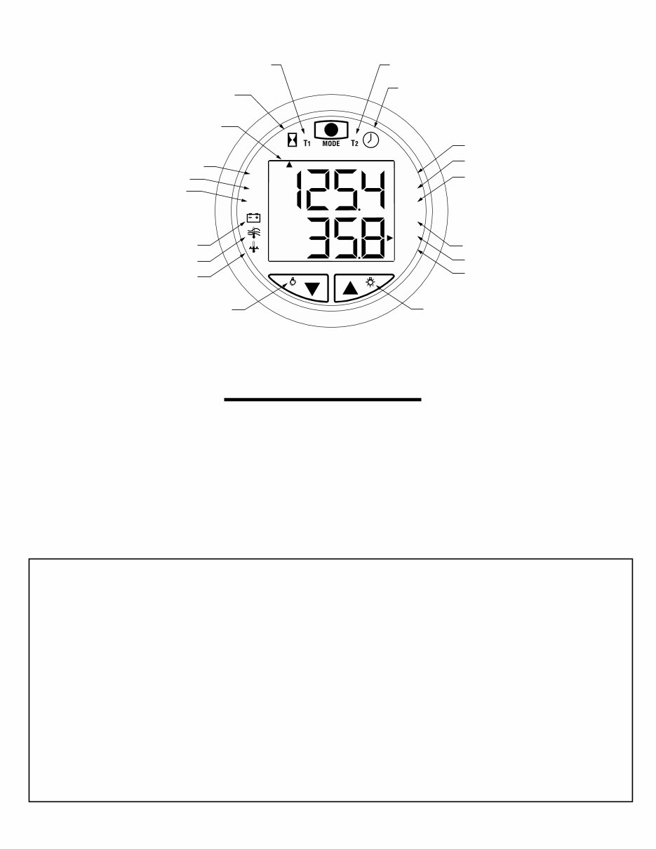
1
Timer (Hrs. & Min.) Timer (Min. & Sec.)
Clock
Illumination On Illumination Off
Depth In:
Feet
Meters
Fathoms
Voltmeter
Air Temp.
Water Temp.
Depth Sounder
Shallow Alarm
Deep Alarm
Keel Offset
Distance Log
(Statute or Nautical miles)
Miles per hour
Knots
Function Indicator
Engine Hourmeter
Key Pad Functions
Description:
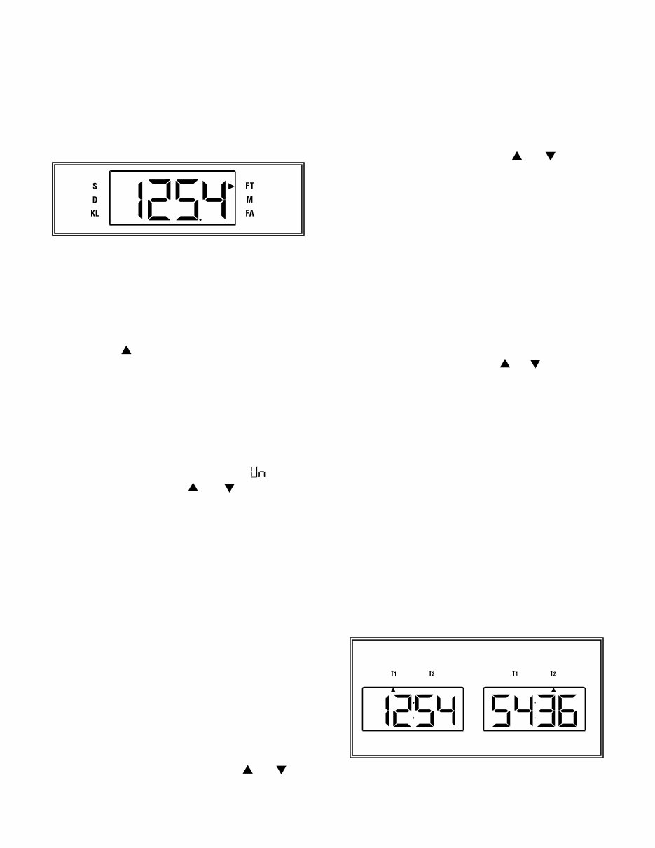
The Faria Pilot System is a multifunctional instrument designed to give two simultaneous readouts of several different and
independent functions on an upper and lower LCD display. The illustration above shows the various functions provided by
the instrument.
WARNING: The depth sounder is not to be used for navigation or as a device to avoid grounding which may result in boat
damage or personal injury. Always use caution operating in shallow areas and maintain a very slow speed. Be aware that
depths may change too quickly for you to avoid grounding.
Index:
Installation...................................................................................................................................2
Operation.....................................................................................................................................3
Upper Display Functions
Depth Finder ................................................................................................................................3
Timer .............................................................................................................................................4
Clock.............................................................................................................................................4
Hourmeter ................................................................................................................................... 5
Lower Display Functions
Speedometer & Distance Log.....................................................................................................5
Air & Water Temperature..........................................................................................................6
Voltmeter ......................................................................................................................................6
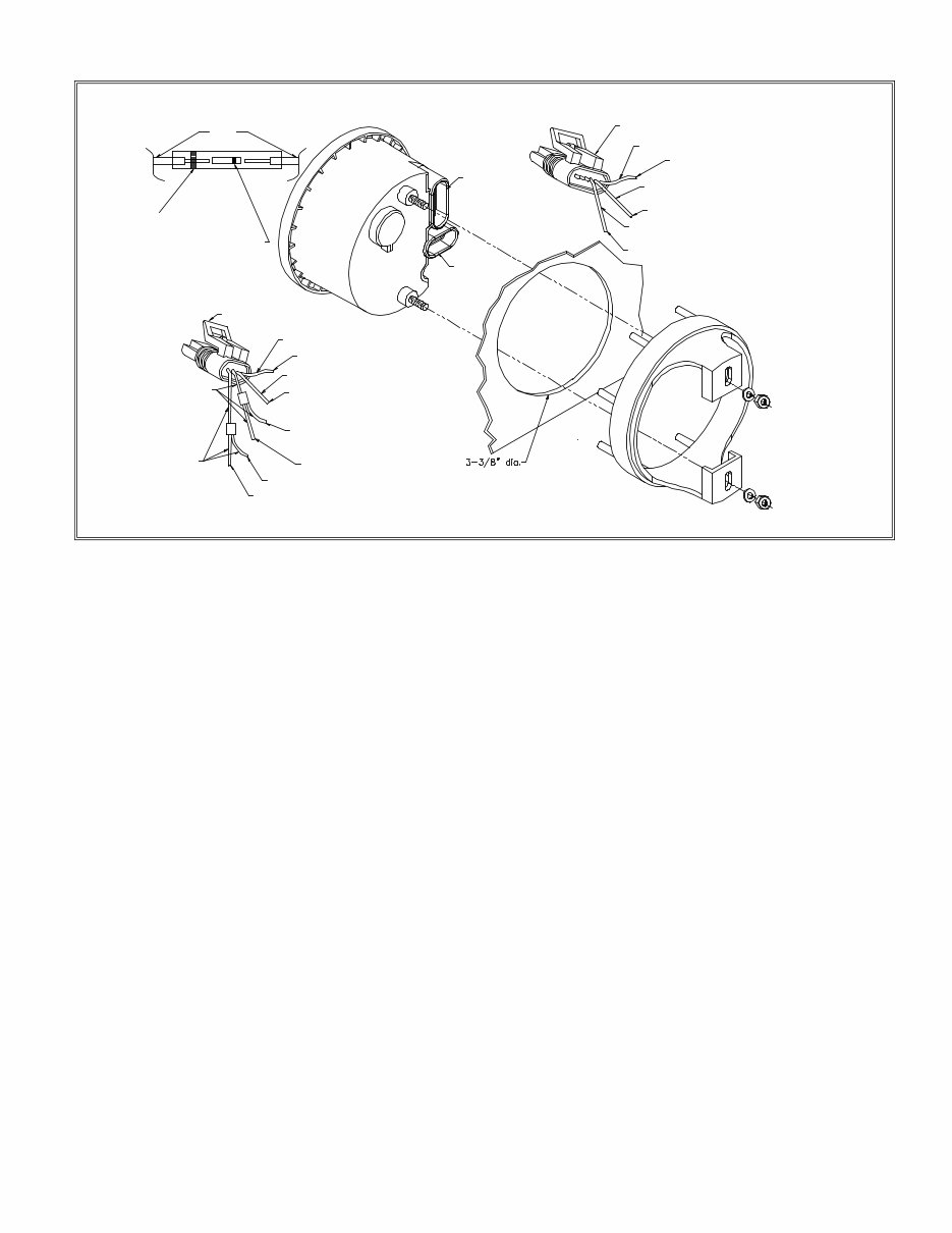
Used for all splices.
Wires
Heat Shrink Tube
(red or blue)
Metal Butt Connector
(red or blue).
Used for all splices.
6-Pin Female
Connector
4-Pin Female
Connector
6-Pin Male Connector
GREEN
To Speed/Temp Transducer/Sensor
Cable (Green) Speed
RED & WHITE
To Air Temp Harness (White)
(Optional)
White
To Speed/Temp Trasducer/Sensor Cable (White)
Water Temp
Black
Red
4-Pin Male
Connector
BLUE
Depth Transducer/Sensor Cable (Blue)
BLACK & WHITE
To Depth Transducer/Sensor Cable (Black)
Ground
To Both Transducer/Sensor Cables
Shield & Water Temp Harness (Brown) and
Air Temp Harness (Black)
(Optional)
To Boat Ground (Black)
To Speed/Temp Sensor Cable+ (Red)
To Boat Battery+ (NOT IGNITION)
2
Installation:
CAUTION: Disconnect the battery during installation.
Tighten nuts on the back clamp only slightly more than
you can tighten with your fingers. Six inch-pounds of
torque are sufficient. Over-tightening could result in
damage to the instrument and may void your warranty.
1. Cut a 3-3/8” diameter hole in the dash and mount the
gauge with the back clamp supplied.
Follow the enclosed Airmar Technology Corporation
instructions for installing the transducer/sensor. Once
the transducer/sensor is installed and you have lead the
cables to the Pilot, connect the wires from the
transducer/sensor to the corresponding 4 or 6-pin
connectors as illustrated using the butt connectors
supplied. The butt connectors have a heat activated
waterproofing. Once the butt connections have been
crimped slowly apply heat with a heat gun until you see
sealant coming out of the connector ends. It is
recommended to wrap the connections together with
electrical tape for further protection.
(4 - Pin Connector)
2. It is recommended that insulated wire terminals,
preferably ring type, be used on the connections to the
power source. Be certain to use stranded, insulated
wire, not lighter than 18 gauge, that is approved for
marine use.
3. Connect a wire to the boat’s electrical ground usually
available at several locations near the instrument panel.
Connect the other end to one of the connector's black
wires to the transducer/sensor cable shielding; the water
temp harness brown (optional: and air temp harness
black) using a blue connector.
4. Connect the red wire to any continuous B+ or
positive “+” circuit of the boat’s 12 Volt DC electrical
system. This circuit must not be ignition key
activated as the clock requires a very small but
continuous B+ supply. Using red connectors: Connect
the other end to one of the connector's red wires.
Connect the connector's other wire to the
transducer/sensor cable red.
5. Connect the connector's black & white wire to the
transducer/sensor cable black, using a red connector.
6. Connect the connector's blue wire to the
transducer/sensor cable blue, using a red connector.
(6 - Pin Connector)
1. Connect the connector's white wire to the
transducer/sensor cable white, using a red connector.
2. Connect the connector's green wire to the
transducer/sensor cable green, using a red connector.
3.(Optional: Connect the connector's red and white wire
to the air temp harness white, using a red connector)
NOTE: If the transducer cables are not connected
properly or not plugged into the Pilot, the display will
blink when the power is applied to the unit.
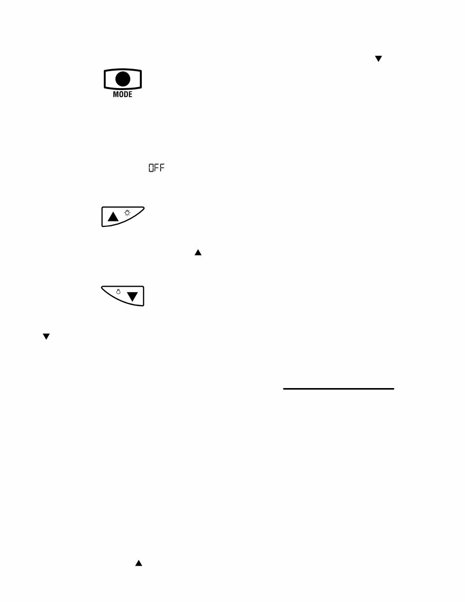
Power ON:
To turn the Pilot on, press the MODE button on the top
of the instrument. The Pilot will beep and the LCD will
illuminate and display the functions last selected.
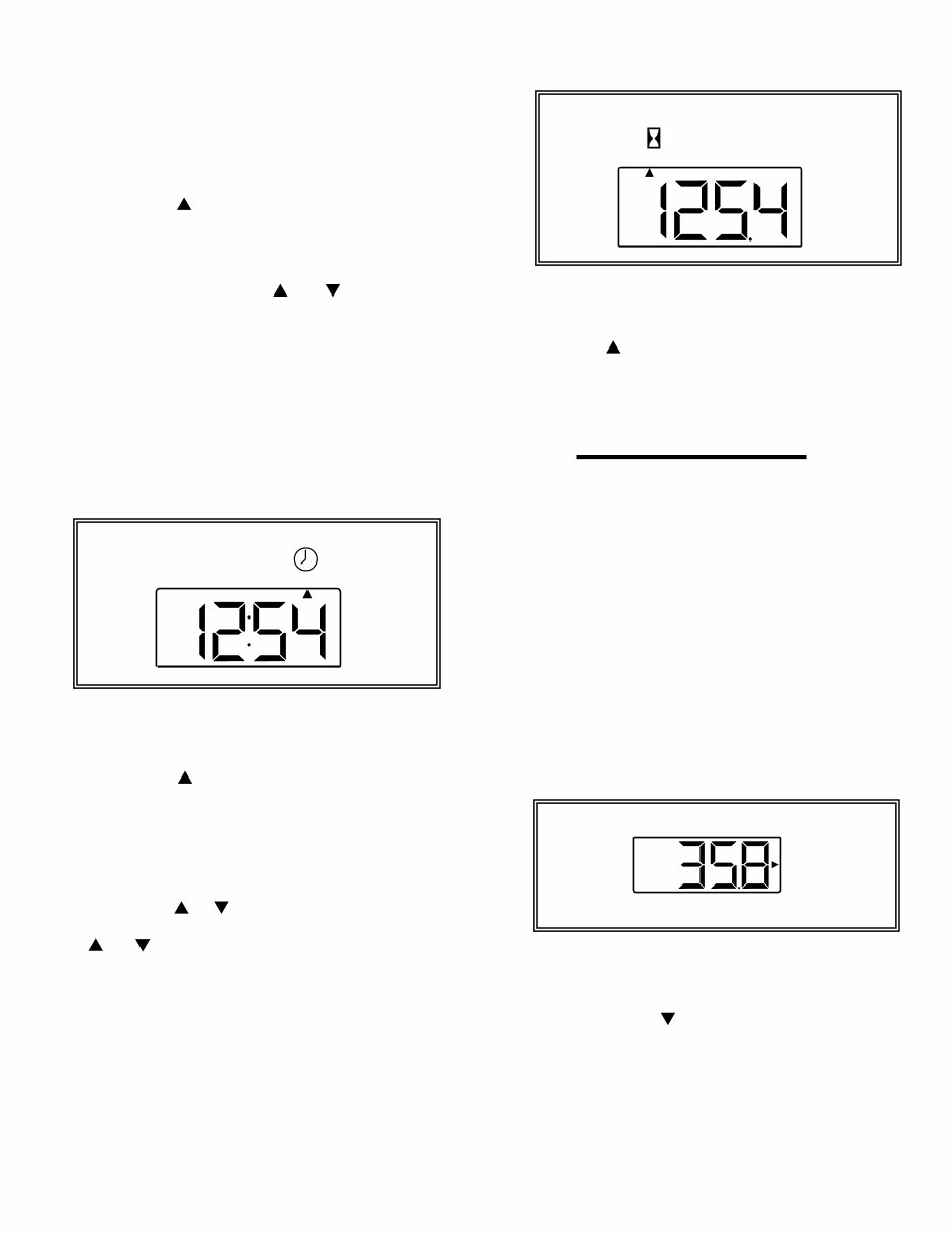
Power OFF:
To turn the Pilot off, press and hold the MODE
button. The Pilot will beep. Continue holding the MODE
button. The top display will show “ ” and the bottom
display will count down: 3, 2, 1. The LCD will
then extinguish.
Illumination On:
To turn on the dial illumination, press the right Up ( )
arrow with the Pilot in the normal mode.
Illumination Off:
To turn off the dial illumination, press the left Down
( ) arrow with the Pilot in the normal mode.
Normal Mode:
Pilot is operating showing the last selected Functions.
NOTE: When in either the Select or Edit
Modes if no button is pushed for 5 seconds
the Pilot will revert to the Normal Mode
functions last used or to the new settings. If
no button is pushed for 24 hours the Pilot
will shut off.
Select Mode:
The Select Mode allows selection of the upper or lower
LCD displays and or the particular function desired in
either display.
Activating the Select Mode:
To activate the Select Mode, press the MODE button
quickly. The Pilot will beep and the last selected active
display (upper or lower) will flash.
Selecting upper or lower active display:
Activate the Select Mode and while the display is
flashing, press the Up arrow ( ) to select the upper
3
Operation:
display as active or the Down arrow ( ) to select the
lower display as the active display.
Selecting display function, (moving the Function
Indicator):
When in the Select Mode in the desired active display and
while the display is flashing press the MODE button
quickly again. The Function Indicator will move from
function to function around the selected active display
and the Pilot will beep each time the MODE button is
pressed. Stop at the desired function.
Edit Mode:
The Edit Mode allows you to set the following:
Depth Sounder: shallow alarm, deep alarm, keel offset,
scale units (feet, fathoms or meters).
Timer: reset to zero.
Clock: hours and minutes.
Distance Log: reset to zero, speed scale units (miles per
hour or knots,) calibrate speed and distance (statute miles
or nautical miles).
Thermometers air and water: scale units (Fahrenheit or
Centigrade).
Selecting the Edit Mode:
When the desired display function is selected, press and
hold the MODE button until the Pilot beeps. The Edit
Mode will activate. If no buttons are pushed within 5
seconds, the Pilot will revert automatically to the Normal
Mode. You can also enter the Edit Mode while in the
Select Mode. The Pilot display will then stop flashing
(Select Mode) indicating the change to the Edit Mode.
The operation of various edit modes will be separately
explained for each function throughout this manual.
Upper Display Functions
Depth Sounder:
Description:
Depending on the bottom conditions the depth finder will
read to 300ft. or the corresponding number of meters or
fathoms to the nearest 1/10
th
(0.1). NOTE: A 600 ft.
Triducer is also available.
The depth finder has an audible and LCD displayed depth
alarm with adjustable shallow and deep limits and a depth
below keel offset feature. These settings once made are
stored in memory and will remain even if the battery is
disconnected.
Setting the Deep Alarm:
Press and hold the MODE button until the Pilot beeps
to select the Edit Mode. Continue pressing the MODE
button quickly until the Function Indicator points to the
"D" indicating the deep depth alarm setting. This is the
deepest water that will activate the alarm. Press and hold
the Up or Down arrow keypads ( ) / ( ) to adjust
the reading to the desired depth.
Setting the Keel Offset:
Keel Offset can be set so that the depth sounder either
shows the depth below the keel, (set the offset to be the
depth between the transducer and the bottom of the keel)
or the depth below the transducer (set the offset to 0). For
example if the bottom of the keel is 2 ft. below the
transducer and you want the depth sounder to read the
depth below the keel, the display should be adjusted to
read minus -2.0 “FT”.
Press and hold the MODE button until the Pilot beeps
to select the Edit Mode. Continue pressing the MODE
button quickly until the Function Indicator points to the
“KL” indicating the keel offset function. Press and hold
the Up or Down arrow keypad ( ) / ( ) to adjust the
reading to the desired depth. A minus sign (-) will appear
to the left of the setting.
Loss of Signal:
If the signal is lost due to depths below 300 ft., depths
above 2 ft. or a disconnected or broken cable, a dashed
line will appear in the upper display signifying loss of
signal. If the upper display depth sounder function is
active the dashed line will illuminate and hold. If any
other upper display function is active the dashed line will
flash on and off alternately with the active function’s
readout.
Timer:
Description:
The timer operates simultaneously in hours, minutes and
seconds. The timer is viewed in the Normal Mode as
either hours and minutes (T
1
), or minutes and seconds
(T
2
).
Operation:
Selecting the Depth Sounder Function:
Press the MODE button and activate the Select Mode.
Press the Up ( ) arrow to select the upper display.
Continue pressing the MODE button again until the
Function Indicator is pointing to FT, M or FA.
(The Function Indicator will automatically point to the
last unit type selected. You are now in the Depth Finder
function.)
Selecting the depth Sounder Units.
Press and hold the MODE button until the Pilot beeps
to select the Edit Mode. Continue pressing the MODE
button quickly until the upper display reads " " (units).
Press either arrow button ( ) / ( ) to move the
function indicator to the desired units either Feet (F),
Meters (M) or Fathoms (FA).
Depth alarms:
When the shallow depth setting is read by the depth
sounder, the Function Indicator will flash on the LCD
next to the “S” and the audible alarm will sound rapidly.
When the deep depth setting is read by the depth sounder,
the Function Indicator will flash on the LCD next to the
"D" and the audible alarm will sound at 2 beeps per
second.
NOTE: Once a keel offset is programmed, the depth
below the keel will activate the shallow and deep alarms.
NOTE: To fully deactivate an alarm, reset it to zero.
Setting the Shallow Alarm:
Press and hold the MODE button until the Pilot beeps
to select the Edit Mode. Continue pressing the MODE
button quickly until the Function Indicator points to the
“S” indicating the shallow depth alarm setting. This is the
shallowest water that will activate the alarm. Press and
hold the Up or Down arrow keypads ( ) / ( ) to
adjust the reading to the desired depth.
Depth Sounder Continued:
4
Selecting the Hourmeter:
Press the MODE button and activate the Select Mode.
Press the Up ( ) arrow to select the upper display.
Continue pressing the MODE button again until the
Function Indicator is pointing to the Hourglass.
Lower Display Functions
Speedometer & Distance Log:
Description:
The Speedometer gives digital readings in either Statute
Miles per Hour or Nautical Miles per Hour (knots).
Readings are accurate up to 58 mph (50 kts) in 0.1
increments. Speed calibration can be performed at any
speed by setting the speedometer reading to match GPS,
radar gun, time distance run etc. The Distance Log reads
in either Statute Miles or Nautical Miles in 0.1 increments
depending upon which unit type is selected for the
Speedometer or Log. (Setting units in either function sets
the units for both). Distance Log calibration can also be
performed by setting the Log reading to mach a GPS or
charted distance run. Calibrating the distance Log also
automatically calibrates the Speedometer. (The longer the
distance the more accurate the calibration.)
Operation:
Selecting the Speedometer Function:
Press the MODE button and activate the Select Mode.
Press the Down arrow ( ) to select the lower display.
Continue pressing the MODE button again until the
Function Indicator is pointing to either (MPH) or (KTS).
(The Function Indicator will automatically point to the
last unit type selected. You are now in the Speedometer
function.)
Operation:
Selecting the Timer Functions.
Press the MODE button and activate the Select Mode.
Press the Up ( ) arrow to Select the upper display.
Continue pressing the MODE button again until the
Function Indicator is pointing to either (T
1
) or (T
2
).
Starting and Stopping the Timer.
Press either arrow button ( ) / ( ) to start or stop
the timer at any time.
Resetting the Timer.
Press and hold the MODE button until the Pilot beeps
to select the Edit Mode. Selecting the Edit Mode in either
(T
1
) or (T
2
) will reset the timer to zero.
Clock:
Description:
The clock will run continuously as long as power is
applied to the Pilot. The clock reads hours and minutes.
Operation:
Selecting the Clock Function.
Press the MODE button and activate the Select Mode.
Press the Up ( ) arrow to select the upper display.
Continue pressing the MODE button again until the
Function Indicator is pointing to the clock.
Setting the clock:
Press and hold the MODE button until the Pilot beeps
to select the Edit Mode. Press the Up or Down arrow
keypads once ( ) / ( ) to set each minute. Press and hold
the Up or Down arrow keypads
( ) / ( ) to set the hours. (The minutes will continuously
advance in 10-minute intervals to change the hours.)
Hourmeter:
Description:
The hourmeter is designed to activate when the line
voltage to the Pilot reaches 13.6v DC. This voltage would
indicate that the system is charging with the engine
running.
5
DIS
KTS
MPH
Selecting the Speedometer Units.
Press and hold the MODE button until the Pilot beeps
to select the Edit Mode. Continue pressing the MODE
button quickly until the lower display reads “ ” (units).
Press either arrow button ( ) / ( ) to move the function
indicator to the desired units either Miles per Hour
(MPH), or Knots (KTS).
Calibrating the Speedometer:
Press and hold the MODE button until the Pilot beeps
to select the Edit Mode. Continue pressing the MODE
button quickly until the lower display reads " "
(calibration). Press either arrow button ( ) / ( ) to
change the speed reading to the desired speed.
Selecting the Distance Log Function:
Press the MODE button and activate the Select Mode.
Press the Down arrow ( ) to select the lower
display.
Continue pressing the MODE button again until the
Function Indicator is pointing to (DIS). The Function
Indicator will also automatically point to the last unit type
selected. You are now in the Distance Log Function
Selecting the Distance Log Units.
Press and hold the MODE button until the Pilot beeps
to select the Edit Mode. Continue pressing the MODE
button quickly until the lower display reads “ “(units).
Press either arrow button ( ) / ( ) to move the function
indicator to the desired units either Miles (MPH), or
Nautical Miles (KTS).
Calibrating the Distance Log:
Press and hold the MODE button until the Pilot beeps
to select the Edit Mode. Continue pressing the MODE
button quickly until the lower display reads “ ”
(calibration). Press either arrow button ( ) / ( ) to
change the Log reading to the desired distance.
Clearing the Distance Log:
Press and hold the MODE button until the Pilot beeps
to select the Edit Mode. Continue pressing the MODE
button quickly until the lower display reads “ ”(clear).
Press either arrow button ( ) / ( ) to clear the Log
reading to zero.
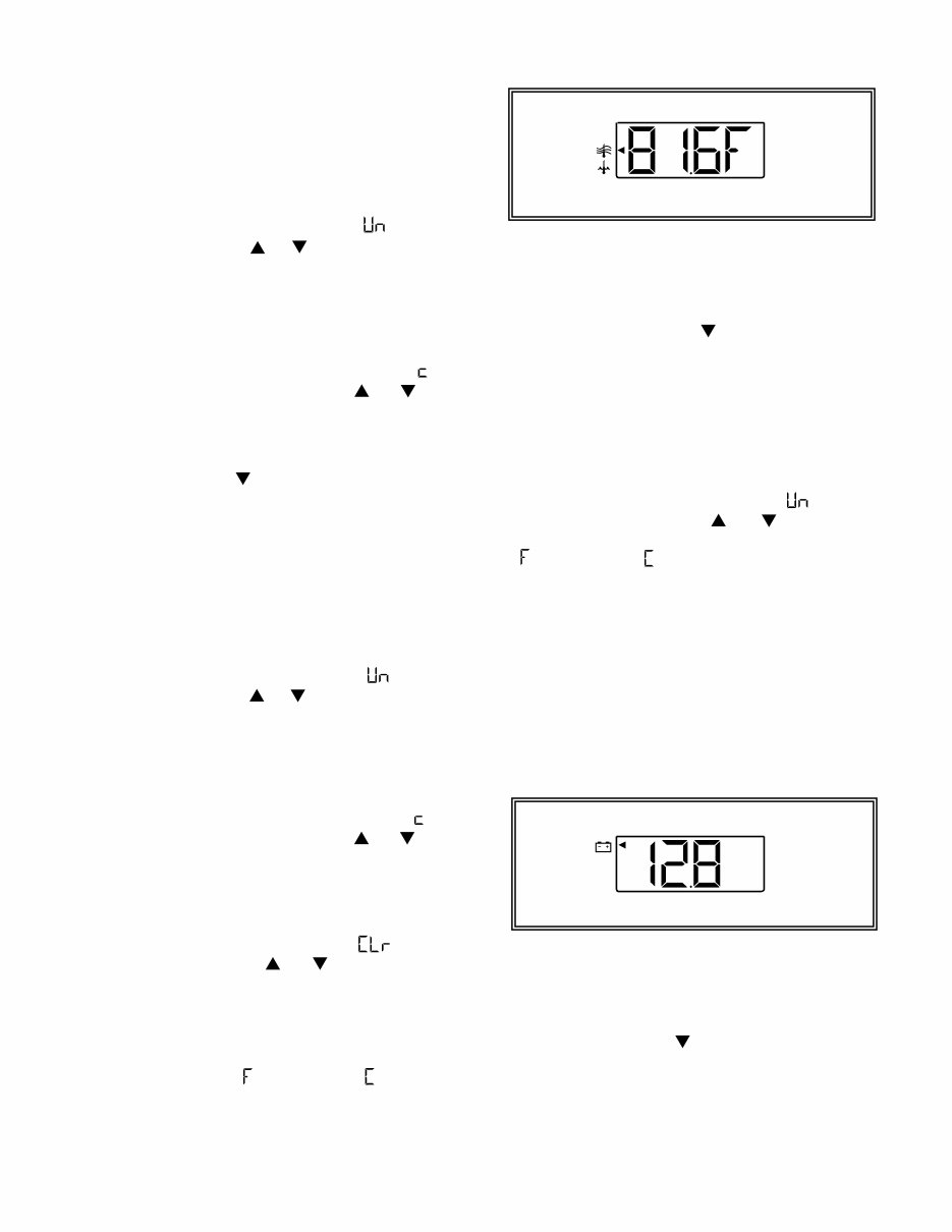
Water and Air / Bait-well Temperature:
Description:
The Pilot will monitor water surface temperature. The
(Setting units Fahrenheit ( ), or Centigrade ( ), in either
function sets the units for both). (A second temperature,
either air or bait-well may be monitored when the unit is
equipped with the optional sender.)
Operation:
Selecting the Air / Water Temperature Function
Press the MODE button and activate the Select Mode.
Press the Down arrow ( ) to Select the lower
display.
Continue pressing the MODE button again until the
Function Indicator is pointing to either the upper icon
(Air/Bait-well Temp.) or the lower icon (Water Temp.)
Selecting the Air / Water Temperature Units
Press and hold the MODE button until the Pilot beeps
to select Edit Mode. Continue pressing the MODE
button quickly until the lower display reads “ ” (units).
Press either arrow button ( ) / ( ) to move the
function indicator to the desired units either Fahrenheit
( ) or Centigrade ( ).
Voltmeter:
Description:
The Voltmeter continuously monitors the 12v DC power
supplied to the Pilot. The Voltmeter has a low and high
voltage alarm feature. If line voltage drops to 10v DC or
rises above 16v DC the Voltmeter Function will
automatically activate. The LCD display will flash and the
Pilot will Beep every 15 seconds to warn of a low or high
voltage condition. If voltage lower than 13v DC persists
for 24 hours the Pilot will shut off.
Selecting the Voltmeter Function:
Press the MODE button and activate the Select Mode.
Press the Down arrow ( ) to select the lower display.
Continue pressing the MODE button again until the
Function Indicator is pointing to the Battery icon.
6

IS0123B ECR#867
You're Reading a Preview
What's Included?
Fast Download Speeds
Online & Offline Access
Access PDF Contents & Bookmarks
Full Search Facility
Print one or all pages of your manual
$26.99
$35.99
Viewed 80 Times Today


Secure transaction
What's Included?
Fast Download Speeds
Online & Offline Access
Access PDF Contents & Bookmarks
Full Search Facility
Print one or all pages of your manual
$26.99
$35.99
- This manual provides installation and operation instructions for the Tige Faria Pilot Gauge, covering all models: PCM-2, PCM-3, PCM-4, PCM-5, PCM-6, PCM-7, PCM-8, PCM-9, PCM-10, PCM-11, PCM-12, PCM-13, PCM-14, PCM-15, PCM-16, PCM-17, PCM-18, PCM-19, PCM-20.
- The manual contains instructions on installation, operation, and troubleshooting of the gauge. It also includes diagrams and illustrations to aid in understanding the components and features of the gauge. Additionally, the manual provides safety information and maintenance tips for optimal gauge condition.
- The Tige Faria Pilot Gauge is designed to deliver accurate and reliable readings for various marine applications. This manual is valuable for both professional mechanics and DIY enthusiasts, ensuring maximum utilization of the gauge.
- Acquire this manual now to instantly access it through a download link. It is an essential resource for any Tige Faria Pilot Gauge owner.


