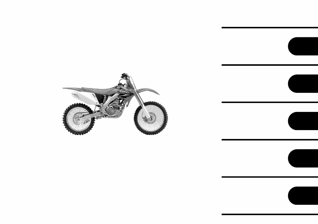
1 2 3 4 5 PART NUMBER INDEX FOREWORD INDEX ENGINE GROUP FRAME GROUP PART NAME INDEX [CRF250R4]
1 2007.08.10 E 1 1 2 3 4 5 • This parts catalogue has been created as of August 10, 2007. • Since this date, the sales practice for repair parts may have been changed or the parts may have been eliminated (listed for those not for sale). • The modified information is reflected on the latest Electronic Parts Catalogue (EPC). Also, refer to the parts catalogue news for any change. • See the parts catalogue news for any revision that is made after August 10, 2007. • Always specify the part number when ordering a part. • Check the model, type, serial numbers, color, maker, and the size as needed before ordering a part. • Note that the illustrations (part drawings) can differ from the ac- tual parts in shape. They are given just to help you to refer to the parts. • When modifications or additions to this parts catalogue are made, a revised edition will be issued at an appropriate time, with successively progressing revision numbers on the cov- er. We recommend obtaining such revisions in order to keep your parts catalogue up-to-date at all times. To check whether a parts catalogue revision has been issued, please contact your Honda distributor. Initial version issue date September 10, 2003 Honda Motor Co., Ltd. • Instruction for use of parts catalogue ......................... 1 • How to refer to the part information ............................ 2 • Part catalogue structure ............................................. 3 • When the parts were revised ...................................... 4 • Abbreviations used in the parts catalogue.................. 4 • Part block and serial number check ........................... 5 • Models, parts catalogue codes and applicable serial numbers ........................................................... 6 • Fuel hose, general purpose hoses and vinyl hose ........................................................................... 8 • FLAT RATE SERVICE TIME .................................... 12 • Illustrated index ........................................................ 17 • ENGINE GROUP..................................................... 24 • FRAME GROUP ...................................................... 62 • PART NO. INDEX................................................... 114 • PART NAME INDEX............................................... 121 B 1 CONTENTS Address No. Page B 1 B 2 B 3 B 4 B 4 B 5 B 6 B 8 B12 C 1 D 1 G 1 K 1 L 1 Instruction for use of parts catalogue
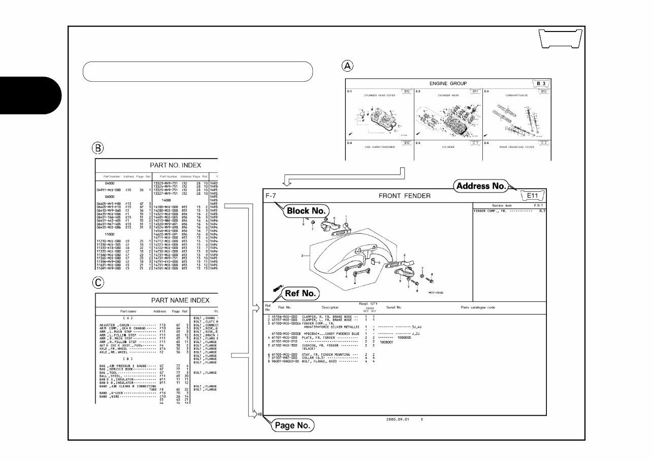
2 1 2007.08.10 E B 2 Reference with “Part number index” Reference with “Part name index” How to refer to the part information Reference with “Illustrated index”
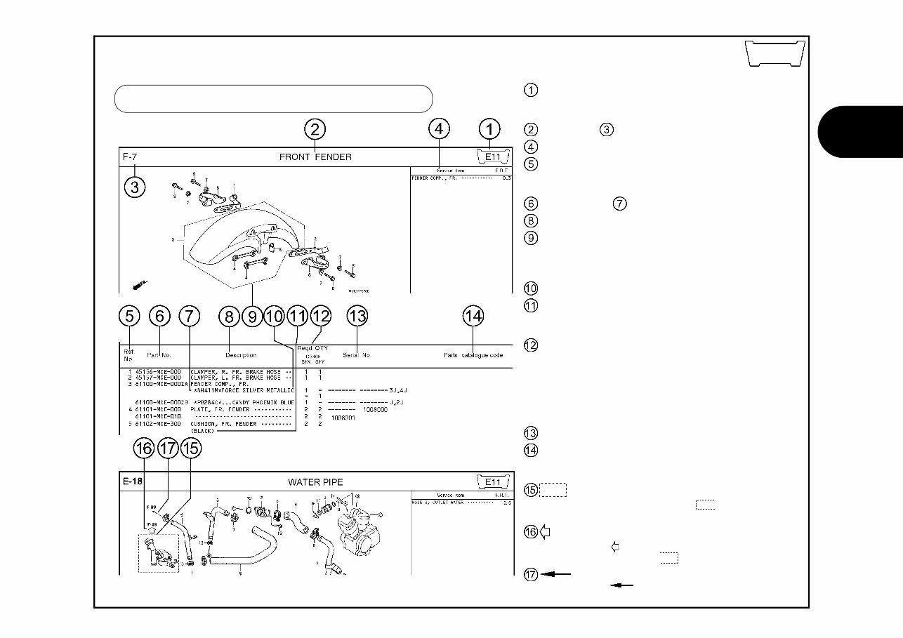
3 1 2007.08.10 E B 3 Part catalogue structure Address number • Address No. is provided (in place of the page No.) to help you refer to the part with the part No. or part name. Block title Block number Service item/Flat rate time Reference number • Title number marked with the parenthesis or parentheses indicates that it continues from the previous page. Part number Honda color code Description Assemblies • Sections framed with broken lines in the exploded view drawings are available as complete assemblies. (Their in- dividual parts can also be obtained.) Color description Note • Notes are shown with the parentheses in the part name column. Required quantity • Reqd. QTY shown in the parenthesis or parentheses indi- cates the optional part. • Reqd. QTY marked with “N” indicates the optional part that should be selected as needed. • Reqd. QTY indicates the number of the part used in the block. Serial number Parts catalogue code • When the parts catalogue code column is blank, it indi- cates that the part is applicable to all codes. • Parts enclosed within a dotted line are covered in a different block. • A hollow arrow indicates the block No. for the parts en- closed within a dotted line . • A solid arrow indicates the block No. the part in question is connected to.
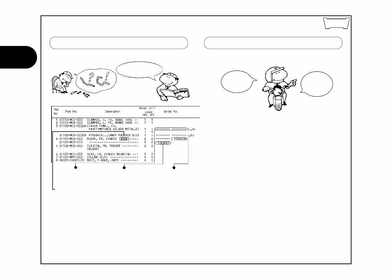
4 1 2007.08.10 E B 4 When the parts were revised Be sure to check the serial number!! The number has been used from the initial model without revision. When shown at the left side, it is applicable to the models of No.1008001 and the subsequent numbers. When shown at the right side, it is applicable to the models up to No.1008000. • The parts listed with "###" at the end of the parts name have limited supply period (parts not for sale). * “L.” or “R.” in the description of a part stands for the LEFT hand side or the RIGHT hand side. Determine the left or right as if you were in the motorcycle seat. • The following abbreviations are used in this parts catalogue. A ........... Ampere ABS ....... Anti-lock brake system A.C. ....... Alternating current A.M. ...... Attaching mark ASSY . .... Assembly C.D.I. ..... Capacitive discharge ignition COMP . ... Complete D.C. ....... Direct current EX. ........ Exhaust FR. ........ Front G ........... Gram HEX. ..... Hexagonal IN. ......... Inlet KPH ...... Kilometers per hour L. ............Left L (100L) .Link (100 Links) L.E.D. .....Light emitted diode MM .........Millimeter MPH .......Miles per hour R. ...........Right RR. .........Rear STD. .......Standard T (22T) ...Tooth (22 Teeth) TCS ........Traction control system T.M. ........Transcript mark V ............Volt W ...........Watt WL .........With labelling WOL .......Without labelling Abbreviations used in the parts catalogue RIGHT is abbreviated as “R.” “L.” stands for LEFT
5 1 2007.08.10 E B 5 Part block and serial number check 1 2 3 Required serial number Engine parts E-1~ Engine serial number Carburetor parts E-18~ Carburetor serial number Frame parts F-1~ Frame serial number Part block Check point 1 2 3
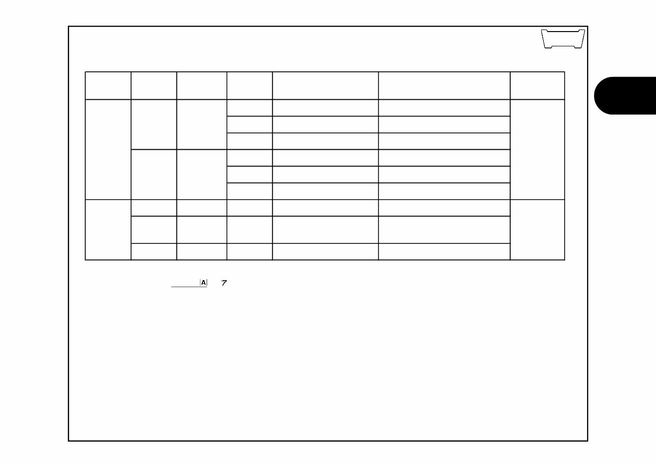
6 1 2007.08.10 E Models, parts catalogue codes and applicable serial Nos. given in this parts catalogue can be identified as follows. Parts with parts catalogue codes are exclusive for models destined for countries designated. If no area codes are listed, parts are for common use. Models, parts catalogue codes and applicable serial numbers Model Area code Type Parts catalogue code Applicable engine serial No. Applicable frame serial No. Applicable carburetor serial No. ED ME10E-2000001~2049999 JH2ME10A*4M000001~4M009999 ED/A ME10E-2050001~2099999 JH2ME10A*4K010001~4K099999 U ME10E-2000001~2049999 JH2ME10U*4M000001~4M049999 U/A ME10E-2050001~2099999 JH2ME10U*4K050001~4K099999 ED ME10E-2100001~2119999 JH2ME10A*5M100001~5M109999 ED/A ME10E-2120001~2149999 JH2ME10A*5K110001~5K149999 ED/B ME10E-2150001~2199999 JH2ME10A*5M150001~5M199999 U ME10E-2100001~2119999 JH2ME10U*5M100001~5M109999 U/A ME10E-2120001~2149999 JH2ME10U*5K110001~5K149999 U/B ME10E-2150001~2199999 JH2ME10U*5M150001~5M199999 ED ME10E-2200001~2229999 JH2ME10A*6M200001~6M209999 ED/A ME10E-2230001~2239999 JH2ME10A*6K210001~6K219999 ED/B ME10E-2240001~2249999 JH2ME10A*6M230001~6M239999 U ME10E-2200001~2229999 JH2ME10U*6M200001~6M209999 U/A ME10E-2230001~2239999 JH2ME10U*6K210001~6K219999 U/B ME10E-2240001~2249999 JH2ME10U*6M230001~6M239999 U CRF250R5 CRF250R6 ED U CRF250R4 European direct sales Australia European direct sales ED U ED Australia European direct sales Australia FCR01A A FCR01B A FCR12A A B 6
7 1 2007.08.10 E B 7 * Of carburetor/throttle body identification numbers, only the portions underlined in the example below are used for registration. FCR01A KC Model Area code Type Parts catalogue code Applicable engine serial No. Applicable frame serial No. Applicable carburetor serial No. ED ME10E-2300001~2319999 JH2ME10A*7M300001~7M309999 ED/A ME10E-2320001~2329999 JH2ME10A*7K310001~7K319999 ED/B ME10E-2330001~2339999 JH2ME10A*7M330001~7M339999 U ME10E-2300001~2319999 JH2ME10U*7M300001~7M309999 U/A ME10E-2320001~2329999 JH2ME10U*7K310001~7K319999 U/B ME10E-2330001~2339999 JH2ME10U*7M330001~7M339999 DE Denmark DE ME10E-2400001~ JH2ME10A*8M400001~ ED European direct sales ED ME10E-2400001~ JH2ME10A*8M400001~ U Australia U ME10E-2400001~ JH2ME10U*8M400001~ FCR12B A FCR12C A European direct sales Australia CRF250R8 CRF250R7 ED U
The Sea Ray 340 Sundancer Parts Manual is an essential resource for professional mechanics and DIY enthusiasts alike. It contains detailed diagrams and instructions for replacing and repairing parts of the Sea Ray 340 Sundancer. This manual covers various models including Sea Ray 340 Sundancer, Sea Ray 340 Sundancer II, Sea Ray 340 Sundancer III, Sea Ray 340 Sundancer IV, and Sea Ray 340 Sundancer V.
Inside, you'll find comprehensive descriptions of the parts and components, along with step-by-step installation and repair guidance. Additionally, it offers troubleshooting tips and advice for identifying and resolving common issues. Whether you're a professional mechanic or a passionate DIY enthusiast, this manual is indispensable for maintaining the smooth and efficient operation of your Sea Ray 340 Sundancer.
The Sea Ray 340 Sundancer Parts Manual is available for instant download in digital format. It's easy to use and navigate, making it a convenient resource for all your repair and maintenance needs.