


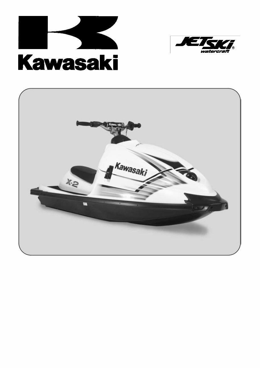
X-2
JET SKI
®
Watercraft
Service Manual
is a trademark of Kawasaki Heavy Industries, Ltd. registered in U.S.A., Japan,
Austria, Benelux, Sweden, Denmark, Switzerland, France, Canada, Finland, Norway, Greece, Italy,
U.K., Portugal, Thailand, and Taiwan.
KAWASAKI JET SKI is a trademark of Kawasaki Heavy Industries, Ltd. registered in Australia.
This quick reference guide will assist
you in locating a desired topic or pro-
cedure.
•Bend the pages back to match the
black tab of the desired chapter num-
ber with the black tab on the edge at
each table of contents page.
•Refer to the sectional table of contents
for the exact pages to locate the spe-
cific topic required.
Quick Reference Guide
General Information 1
Periodic Maintenance 2
Fuel System 3
Exhaust System 4
Engine Top End 5
Engine Removal/Installation 6
Engine Bottom End 7
Cooling and Bilge Systems 8
Drive System 9
Pump and Impeller 10
Steering 11
Hull/Engine Hood 12
Electrical System 13
Storage 14
Appendix 15

X-2
JET SKI
®
Watercraft
Service Manual
All rights reserved. No parts of this publication may be reproduced, stored in a retrieval system, or
transmitted in any form or by any means, electronic mechanical photocopying, recording or otherwise,
without the prior written permission of Quality Assurance Division/Consumer Products and Machinery
Company/Kawasaki Heavy Industries, Ltd., Japan.
No liability can be accepted for any inaccuracies or omissions in this publication, although every possible
care has been taken to make it as complete and accurate as possible.
The right is reserved to make changes at any time without prior notice and without incurring an obligation
to make such changes to products manufactured previously. See your "JET SKI" watercraft dealer for the
latest information on product improvements incorporated after this publication.
All information contained in this publication is based on the latest product information available at the time
of publication. Illustrations and photographs in this publication are intended for reference use only and may
not depict actual model component parts.
© 2006 Kawasaki Heavy Industries, Ltd. First Edition (1) : Nov. 13, 2006 (K)

LIST OF ABBREVIATIONS
A ampere(s) lb pound(s)
ABDC after bottom dead center m meter(s)
AC alternating current min minute(s)
ATDC after top dead center N newton(s)
BBDC before bottom dead center Pa pascal(s)
BDC bottom dead center PS horsepower
BTDC before top dead center psi pound(s) per square inch
°C degree(s) Celsius r revolution
DC direct current rpm revolution(s) perminute
F farad(s) TDC top dead center
°F degree(s) Fahrenheit TIR total indicator reading
ft foot,feet V volt(s)
g gram(s) W watt(s)
h hour(s) Ω ohm(s)
L liter(s)
Read OWNER’S MANUAL before operating.
MAINTENANCE AND ADJUSTMENTS
Maintenance, replacement, or repair of the emission control devices and systems may
be performed by any marine Sl engine repair establishment or individual.
EMISSION CONTROL INFORMATION
Fuel Information
THIS ENGINE IS CERTIFIED TO OPERATE ON UNLEADED REGULAR GRADE GASOLINE
ONLY.
A minimum of 87 octane of the antiknock index is recommended. The antiknock index is posted
on service station pumps.
Emission Control Information
To protect the environment in which we all live, Kawasaki has incorporated an exhaust emis-
sion control system in compliance with applicable regulations of the United States Environmental
Protection Agency.
Exhaust Emission Control System
This system reduces the amount of pollutants discharged into the atmosphere by the exhaust
of this engine. The fuel, ignition and exhaust systems of this engine have been carefully de-
signed and constructed to ensure an efficient engine with low exhaust pollutant levels.
Maintenance
Proper maintenance and repair are necessary to ensure that watercraft will continue to have
low emission levels. This Service Manual contains those maintenance and repair recommenda-
tions for this engine. Those items identified by the Periodic Maintenance Chart are necessary
to ensure compliance with the applicable standards.
Tampering with Emission Control System Prohibited
Federal law prohibits the following acts or the causing thereof: (1) the removal or rendering
inoperative by any person other than for purposes of maintenance, repair, or replacement, of
any device or element of design incorporated into any new engine for the purposes of emission
control prior to its sale or delivery to the ultimate purchaser or while it is in use, or (2) the use
of the engine after such device or element of design has been removed or rendered inoperative
by any person.
Among those acts presumed to constitute tampering are the acts listed below:
Do not tamper with the original emission related parts.
* CDI Ignition System
* Flame Arrester
* Fuel Filter Screen
* Spark Plugs
* Carburetor and internal parts
Foreword
This manual is designed primarily for use by
trained mechanics in a properly equipped shop.
However, it contains enough detail and basic in-
formation to make it useful to the owner who de-
sires to perform his own basic maintenance and
repair work. A basic knowledge of mechanics,
the proper use of tools, and workshop proce-
dures must be understood in order to carry out
maintenance and repair satisfactorily. When-
ever the owner has insufficient experience or
doubts his ability to do the work, all adjust-
ments, maintenance, and repair should be car-
ried out only by qualified mechanics.
In order to perform the work efficiently and
to avoid costly mistakes, read the text, thor-
oughly familiarize yourself with the procedures
before starting work, and then do the work care-
fully in a clean area. Whenever special tools or
equipment are specified, do not use makeshift
tools or equipment. Precision measurements
can only be made if the proper instruments are
used, and the use of substitute tools may ad-
versely affect safe operation.
For the duration of the warranty period,
we recommend that all repairs and scheduled
maintenance be performed in accordance with
this service manual. Any owner maintenance or
repair procedure not performed in accordance
with this manual may void the warranty.
To get the longest life out of your "JET SKI"
watercraft:
•
Follow the Periodic Maintenance Chart in the
Service Manual.
•
Be alert for problems and non-scheduled
maintenance.
•
Use proper tools and genuine Kawasaki "JET
SKI" watercraft parts. Special tools, gauges,
and testers that are necessary when servic-
ing Kawasaki "JET SKI" watercraft are intro-
duced by the Service Manual. Genuine parts
provided as spare parts are listed in the Parts
Catalog.
•
Follow the procedures in this manual care-
fully. Don’t take shortcuts.
•
Remember to keep complete records of main-
tenance and repair with dates and any new
parts installed.
How to Use This Manual
In this manual, the product is divided into
its major systems and these systems make up
the manual’s chapters. The Quick Reference
Guide shows you all of the product’s system
and assists in locating their chapters. Each
chapter in turn has its own comprehensive Ta-
ble of Contents.
For example, if you want ignition coil informa-
tion, use the Quick Reference Guide to locate
the Electrical System chapter. Then, use the
Table of Contents on the first page of the chap-
ter to find the Ignition Coil section.
Whenever you see these WARNING and
CAUTION symbols, heed their instructions!
Always follow safe operating and maintenance
practices.
WARNING
This warning symbol identifies special
instructions or procedures which, if not
correctly followed, could result in per-
sonal injury, or loss of life.
CAUTION
This caution symbol identifies special
instructions or procedures which, if not
strictly observed, could result in dam-
age to or destruction of equipment.
This manual contains four more symbols (in
addition to WARNING and CAUTION) which will
help you distinguish different types of informa-
tion.
NOTE
○ This note symbol indicates points of par-
ticular interest for more efficient and con-
venient operation.
•
Indicates a procedural step or work to be
done.
○ Indicates a procedural sub-step or how to do
the work of the procedural step it follows. It
also precedes the text of a NOTE.
Indicates a conditional step or what action to
take based on the results of the test or inspec-
tion in the procedural step or sub-step it fol-
lows.
In most chapters an exploded view illustration
of the system components follows the Table of
Contents. In these illustrations you will find the
instructions indicating which parts require spec-
ified tightening torque, oil, grease or a locking
agent during assembly.

GENERAL INFORMATION 1-1
1
General Information
Table of Contents
Before Servicing ..................................................................................................................... 1-2
Model Identification................................................................................................................. 1-9
General Specifications............................................................................................................ 1-10
Unit Conversion Table ............................................................................................................ 1-12
1-2 GENERAL INFORMATION
Before Servicing
Before starting to service a watercraft, careful reading of the applicable section is recommended to
eliminate unnecessary work. Photographs, diagrams, notes, cautions, warnings, and detailed descrip-
tions have been included wherever necessary. Nevertheless, even a detailed account has limitations,
a certain amount of basic knowledge is also required for successful work.
Adjustments
Adjustments shall be made in accordance with the Periodic Maintenance Chart or whenever trou-
bleshooting or presence of symptoms indicate that adjustments may be required. Whenever running
of the engine is required during maintenance it is best to have the watercraft in water.
CAUTION
Do not run the engine without cooling water supply for more than 15 seconds, especially
in high revolutionary speed or severe engine and exhaust system damage will occur.
Auxiliary Cooling
An auxiliary cooling supply may be used if the watercraft cannot be operated in water during adjust-
ments. If possible, always operate the watercraft in water rather them use an auxiliary cooling supply.
•
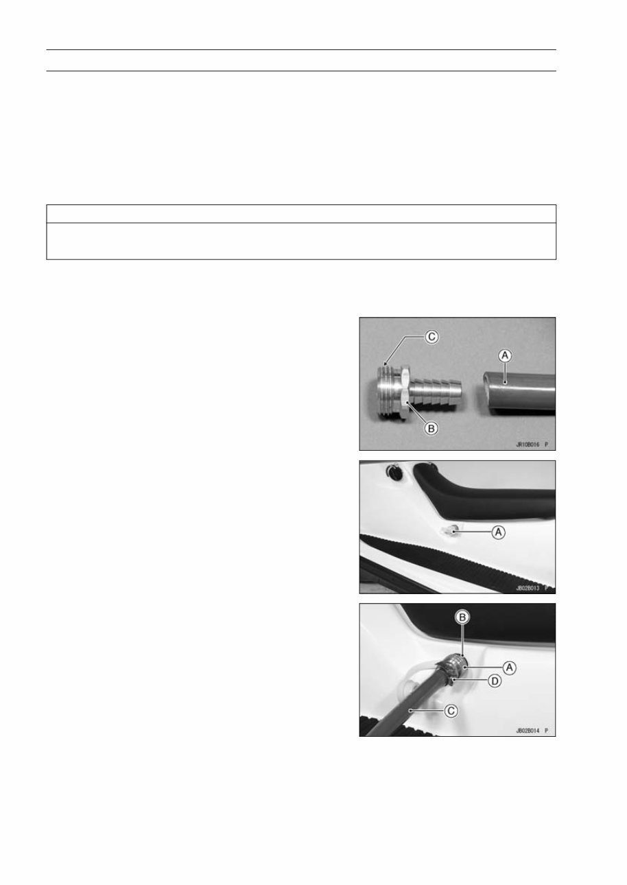
Obtain a standard garden hose [A] and a garden hose
adapter [B] as shown.
C. Thread: Rp 3/4
○ Optional part (P/No. 92005-3748) is available as a garden
hose adapter.
•
Remove the flushing plug [A] at the lower left of the seat.
•
Screw the garden hose adapter [A] onto the flushing fitting
[B].
•
Attach a garden hose [C] to the garden hose adapter and
secure the hose clamp [D].
You're Reading a Preview
What's Included?
 Lifetime Access
Fast Download Speeds
Online & Offline Access
Access PDF Contents & Bookmarks
Full Search Facility
Print one or all pages of your manual
$26.99
Kawasaki Jet Ski X2 Service Manual
Viewed 26 Times Today

What's Included?
Lifetime Access
Fast Download Speeds
Online & Offline Access
Access PDF Contents & Bookmarks
Full Search Facility
Print one or all pages of your manual
$26.99

Secure transaction
What's Included?
Lifetime Access
Fast Download Speeds
Online & Offline Access
Access PDF Contents & Bookmarks
Full Search Facility
Print one or all pages of your manual
Description
This product is a comprehensive service manual for the Kawasaki Jet Ski X2 model. It contains all the information necessary to perform maintenance and repair on the Jet Ski X2. The manual is designed to be easy to use and includes detailed instructions and illustrations for servicing the Jet Ski X2.
This manual includes:
- Step-by-step instructions for performing maintenance on the Jet Ski X2
- Detailed illustrations and diagrams for servicing the Jet Ski X2
- Troubleshooting and repair tips
- Safety information
- Exploded views of Jet Ski X2 components
This service manual is essential for both professional mechanics and DIY enthusiasts. It is the perfect resource for anyone looking to perform maintenance and repair on the Jet Ski X2.


