

Eberspacher Hydronic B5WS and D5WS heater repair service manual
What's Included?
Fast Download Speeds
Online & Offline Access
Access PDF Contents & Bookmarks
Full Search Facility
Print one or all pages of your manual
Eberspächer
®
J. Eberspächer
GmbH & Co. KG
Eberspächerstr. 24
D -73730 Esslingen
Telefon (zentral)
(07 11) 9 39 - 00
Telefax
(07 11) 9 39 - 05 00
www.eberspaecher.com
25 2257 95 15 47 02.2002 Subject to change Printed in Germany © J. Eberspächer GmbH & Co. KG
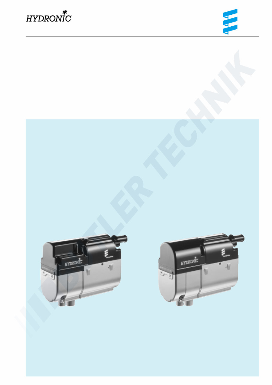
B 4 W SC, B 5 W SC, D 4 W SC and D 5 W SC
The troubleshooting and repair instructions are valid
for the following engine-independent water heaters:
Heaters for petrol
Order No.
HYDRONIC B 4 W SC – 12 volt 20 1824 05 00 00
HYDRONIC B 4 W SC – 12 volt
complete package 20 1821 05 00 00
HYDRONIC B 5 W SC – 12 volt 20 1820 05 00 00
HYDRONIC B 5 W SC – 12 volt
complete package 20 1823 05 00 00
Troubleshooting and repair instructions
Heaters for diesel
Order No.
HYDRONIC D 4 W SC – 12 volt 25 2257 05 00 00
HYDRONIC D 4 W SC – 12 volt
complete package 25 2221 05 00 00
HYDRONIC D 5 W SC – 12 volt 25 2219 05 00 00
HYDRONIC D 5 W SC – 12 volt
complete package 25 2229 05 00 00

2
Contents
These contents provide you with the exact information
about the contents of the troubleshooting and repair
instructions.
If you are looking for a phrase or technical term or need
an explanation for an abbreviation, please use the
corresponding index at the end of the instructions from
page 51.
Chapter Chapter title Chapter contents Page
1 Introduction • Special forms of notation, presentation and icons ......................... 4
• Liability / Guarantee ......................................................................... 4
• Accident prevention ........................................................................ 4
• Important information
– Range of application of HYDRONIC ............................................ 5
– Purpose of HYDRONIC ................................................................. 5
– Initial commissioning of HYDRONIC
respectively function test following repairs ................................. 5
• HYDRONIC documentation
– Contents and purpose of these troubleshooting
and repair instructions ................................................................. 5
– Other HYDRONIC documentation ............................................... 5
• Statutory regulations ........................................................................ 6
– Regulations for installation and repair ........................................ 6
– Regulations for operation ............................................................. 6
• Safety instructions for installation and repair of HYDRONIC ......... 7
• Safety instructions for operation ...................................................... 7
– Emergency shut-down (EMERGENCY OFF) ................................ 7
2 Function and operation • Sectional drawing HYDRONIC B 4 W SC and B 5 W SC ................ 8
• Function diagram HYDRONIC B 4 W SC and B 5 W SC ................ 9
• Control diagram HYDRONIC B 4 W SC and B 5 W SC ................... 9
• Sectional drawing HYDRONIC D 4 W SC and D 5 W SC ............. 10
• Function diagram HYDRONIC D 4 W SC and D 5 W SC .............. 11
• Control diagram HYDRONIC D 4 W SC and D 5 W SC ................ 11
• Description of functions ................................................................. 12
• Control and safety features ............................................................ 12
3 Technical data • HYDRONIC B 4 W SC and B 5 W SC ............................................. 13
• HYDRONIC D 4 W SC and D 5 W SC ............................................ 14
• Water pump .................................................................................... 15
4 Troubleshooting • When faults occur, first check … ................................................... 16
• Controller lock ................................................................................ 16
• Cancel the controller lock ............................................................. 16
• Testing equipment ......................................................................... 16
• Testing equipment
– Diagnosis instrument ................................................................. 17
– Module clock – installed in vehicle ........................................... 17
– Customer service program KD 2000 ......................................... 17
– Radio remote control TP5 ........................................................... 17
• Fault diagnosis with diagnosis instrument .............................. 18, 19
• Fault diagnosis with module clock ................................................ 20
• Fault diagnosis with customer service program KD 2000 ........... 21
• Fault diagnosis with radio remote control TP5 ............................. 22
• Error code table ...................................................................... 23 – 28
Introduction 1
3
Introduction 1
Chapter Chapter title Chapter contents Page
5 Repair instructions • Repair instructions ......................................................................... 29
• Observe following safety instructions
before working on the HYDRONIC ................................................ 29
• Instructions for AMP unlocking tool ............................................... 29
• Fitting HYDRONIC back into the vehicle ...................................... 29
• Assembly drawing .................................................................... 30, 31
• Repair step 1
Dismantle the fan covering ............................................................ 32
• Repair step 2
Dismantle cover for heat exchanger with water pump ................ 32
• Repair step 3
Dismantle controller ...................................................................... 33
Check controller ............................................................................ 33
• Repair step 4
Remove glow plug ......................................................................... 33
• Repair step 5
Remove flame sensor .................................................................... 34
Check flame sensor ....................................................................... 34
• Repair step 6a
Dismantle combustion air fan ....................................................... 35
• Repair step 6b
Measure speed of combustion air fan motor ................................ 36
• Repair step 7a
Remove plug filter .......................................................................... 36
• Repair step 7b
Remove socket .............................................................................. 36
• Repair step 8
Remove combustion chamber ...................................................... 37
• Repair step 9
Remove overheating and temperature sensor ............................. 38
Check overheating and temperature sensor ................................ 38
• Repair step 10
Remove heat exchanger ............................................................... 39
• Repair step 11
Re-mount heat exchanger ............................................................. 39
• Repair step 12
Remove dosing pump –
only HYDRONIC D 4 W SC / D 5 W SC .......................................... 40
• Measuring the fuel quantity ........................................................... 41
6 Wiring diagram • Wiring diagram
HYDRONIC B 4 W SC / B 5 W SC
HYDRONIC D 4 W SC / D 5 W SC ........................................... 42, 43
• Wiring diagram
Controls – part 1 ....................................................................... 44, 45
• Wiring diagram
Controls – part 2 ....................................................................... 46, 47
7 Service • Certification .................................................................................... 48
• Disposal ......................................................................................... 48
• Foreign representatives ........................................................... 49, 50
• List of abbreviations ....................................................................... 51
• Keyword index ............................................................................... 52
4
Introduction 1
Special forms of notation, presentations
and icons
These instructions use special forms of notation and icons
to underline various different contents. Please refer to the
examples below for the meaning and how to behave.
Special forms of notation and presentations
• This point (•) indicates a list introduced by a heading.
– If a “dot” is followed by an indented hyphen (–), this
list is classified under the black dot.
Icons
Regulation
This icon refers you to a statutory regulation. Failure to
comply can possibly lead to the ABG (general type
certification) for HYDRONIC becoming null and void and
to the preclusion of any guarantee or liability on the part
of J. Eberspächer GmbH & Co. KG.
Danger
This icon draws your attention to a threat of danger to life
and limb. Failure to comply can possibly lead to severe
personal injury.
è This arrow refers to the corresponding precautions to
be taken to prevent the danger.
Caution
This icon draws your attention to a dangerous situation for
a person and / or product. Failure to comply can result in
injury to persons or damage to the machine.
è This arrow refers to the corresponding precautions to
be taken to prevent the danger.
This draws your attention to recommendations and helpful
tips for operation, installation and repair of the
HYDRONIC.
Liability / guarantee
Compliance with the official regulations and safety
instructions is a prerequisite for any liability claims.
Failure to comply with the official regulations and safety
instructions precludes any liability on the part of the
heater manufacturer.
Accident prevention
General accident prevention regulations and correspond-
ing workshop and operational protection instructions must
always be observed.
Please note

5
Important information
Range of application of HYDRONIC
The engine-independent water heater HYDRONIC is
intended for installation in the following vehicles,
depending on heater output:
• motorised vehicles of all kinds
• construction machines
• boats, ships and yachts (diesel heaters only).
Caution
• The heater may only be used and operated for the
range of application stated by the manufacturer in full
compliance with the “operating instructions” enclosed
with every heater.
• HYDRONIC B 4 W SC, B 5 W SC, D 4 W SC and
D 5 W SC – 12 volt must not be installed in vehicles
used for the transport of dangerous substances as per
GGVS / TRS003 / ADR / ADR99.
Purpose of HYDRONIC
• Preheating, de-misting windows
• Heating the following and keeping them warm:
– Driver or working cab
– Freight compartments
– Ship’s cabins
– Passenger and crew compartments
– Vehicle engines and additional units.
Given its functional purpose, HYDRONIC is not certified
for the following uses:
• Long-term continuous operation, e.g. pre-heating and
heating of:
– Living areas
– Garages
– Working sheds, weekend houses
and hunting cottages
– Houseboats, etc.
Initial commissioning of HYDRONIC respectively
function test following repairs
• After installation of the heater respectively after repairs
to HYDRONIC, the coolant circuit and the whole fuel
supply system must be carefully vented. Please comply
with the instructions issued by the vehicle manufacturer.
• Prior to a trial run, open all heating circuits
(set the temperature control to “warm”).
• During the trial run of HYDRONIC, check that all water
and fuel connections do not leak and are firmly
connected.
• If HYDRONIC should show a malfunction during opera-
tion, eliminate the problem with a diagnosis device.
Introduction 1
HYDRONIC Documentation
Content and purpose of these troubleshooting
and repair instructions
These instructions are to be used for eliminating faults
and performing repairs on HYDRONIC.
The necessary work must only be carried out by a JE
service partner or correspondingly trained staff.
Other HYDRONIC documentation
Operating instructions
The operating instructions give the customer all neces-
sary information for safe operation of HYDRONIC.
Technical description / Installation instructions
The technical description/installation instructions give the
JE service partner all necessary technical information and
describe correct proper installation of HYDRONIC.
Spare parts list
The spare parts list gives the JE service partner all neces-
sary information for ordering spare parts required for
repair work.
6
Please note
Introduction 1
Statutory regulations
For installation in vehicles subject to the German Regula-
tions Authorising the Use of Vehicles for Road Traffic
(StVZO), the heater has been awarded a “general type
certification (ABG)” with official test symbol marked on the
heater nameplate.
HYDRONIC B 4 W SC S 288
HYDRONIC B 5 W SC S 288
HYDRONIC D 4 W SC S 274
HYDRONIC D 5 W SC S 274
The statutory regulations are compulsory in the scope of
the StVZO and must also be observed in countries where
there are no special regulations.
For installation of the heater in vehicles not subject to the
StVZO (e.g. ships), the specially valid regulations and
installation instructions must be observed.
Regulations for installation and repair
• The year of initial commissioning must be entered
indelibly on the nameplate. For this purpose, 3 year
numbers are printed on the corresponding section of
the nameplate. The respective year number is to be
indicated by removing (peeling off) the two inapplicable
year numbers.
• The heaters are to be installed according to the installa-
tion instructions. Installation is to be checked
a) by type testing of the vehicles as per § 20 StVZO
b) by individual testing as per § 21 StVZO or
c) by a survey as per § 19 StVZO or by an officially
approved surveyor or inspector for motorised
vehicles, a motorised vehicle surveyor or employee
according to section 7.4a of the appendix to StVZO.
In the case of c), this is to be certified stating the vehicle
manufacturer, vehicle type and vehicle ident. number
on the acceptance confirmation contained in the ABG
form. Effectiveness of type certification depends on this.
The acceptance confirmation must always be kept in
the vehicle.
• For installation of the heater in special vehicles
(e.g. vehicles for the transport of dangerous goods),
the regulations applying to such vehicles must be
observed.
• The heater may not be installed in the driver or passen-
ger compartment of buses and coaches with more than
8 seats apart from the driver’s seat.
• The sticker “turn the heater off before refuelling”
included in the scope of supply of the heater must be
affixed to a suitable point of the vehicle (near to the fuel
filler neck).
• The outlet opening must be designed so that a ball
of 16 mm diameter cannot pass through.
• Exhaust pipes must be routed so that any penetration of
exhaust inside the vehicle is not to be expected.
• The functioning of important operational parts of the
vehicle must not be impaired.
• Condensation or penetrated water must not be allowed
to gather in the exhaust pipe. Drain openings are
permitted, consisting of impervious pipes in the interior
which drain the liquid to the outside.
• The opening of the exhaust pipe should be routed
upwards, to the side, or when the exhaust pipe is routed
under the bottom of the vehicle, close to the side or rear
end of the driver’s cab or vehicle.
• The necessary combustion air must be taken in from the
outside.
• The opening of the combustion air intake must be
designed so that a ball of 16 mm diameter cannot pass
through.
• Electrical cables, switchgear and controllers for the
heater must be arranged in the vehicle so that
troublefree operation is not impaired under normal
operating conditions.
All pipes leading out from the heaters must be
splashproof at the leadthrough.
• The corresponding operating condition (at least
switched on or off) must be clearly obvious for the user.
• §§ 45 and 46 StVZO are to be observed for the routing of
fuel pipes and installation of additional fuel tanks.
Excerpt from §§ 45 and 46 StVZO:
– In the case of buses and coaches, fuel tanks may not
be located in the passenger or driver’s compartment.
They must be arranged so that the exits from the bus
are not at any risk in the case of a fire.
– In the case of buses and coaches, fuel pipes may not
be located in the passenger or driver’s compartment.
Regulations for operation
• The heater must be switched off when refuelling.
• Operation of the heater is not allowed in closed rooms,
such as:
– garages
– underground car parks
– multi-storey car parks.
• The acceptance confirmation is enclosed with the
documents for HYDRONIC.
7
Safety instructions for installation and repair
of HYDRONIC
Danger
Risk of injury, burning and fire!
• Disconnect the vehicle battery before starting any work
on HYDRONIC.
• Always switch HYDRONIC off and let all hot parts cool
down prior to repairs.
Caution
Important instructions for installation and repair
of HYDRONIC
• The heater must only be installed by a JE service
partner authorised by the manufacturer, according to
the specifications made in this document and possibly
any special installation suggestions, or repaired in the
case of repairs or guarantee claims.
• Repairs by unauthorised third parties and / or with non-
original spare parts are dangerous and therefore not
allowed. They make the general type certification (ABG)
of the heater invalid and thus in the case of motorised
vehicles, under certain circumstances also the general
operating permit (ABE) of the vehicle.
• The following are not allowed:
– Modifications to heating-relevant components.
– Use of third-party components not approved by
Eberspächer.
– Failure during installation or operation to comply
with statutory and safety regulations or regulations
relevant to function, as stipulated in the installation
instructions and operation instructions.
This applies in particular to the electrical wiring (circuit
diagrams), fuel supply, combustion air system and
exhaust system.
• Only original accessories and original spares may be
used for installation or repairs.
• Only the controls approved by Eberspächer may be
used to operate HYDRONIC.
The use of other controls can cause malfunctions of the
heater / heating operation.
• Before installing a heater in another vehicle, those parts
of the heater which convey water must be rinsed with
clear water.
• Fuel pipes and exhaust pipes must be fastened
securely (recommended spacing 50 cm) to avoid
damage from vibrations.
• Ensure that the insulation of electric cables etc. cannot
be damaged by chafing, buckling, clamping or heat
development.
Introduction 1
• Failure to comply with the statutory and safety
regulations and / or specifications relevant to functions
makes the ABG of HYDRONIC null and void and
releases J. Eberspächer GmbH & Co. KG from any
guarantee or liability.
Other “safety instructions and important information for the
installation and repair of HYDRONIC” are printed directly
in the corresponding sections of these troubleshooting
and repair instructions.
Safety instructions for operation
Caution
• The heater may not be operated wherever inflammable
fumes or dust can be produced, e.g. near to
– fuel depots
– coal depots
– wood storage yards
– cereal storage facilities.
• HYDRONIC’s after-running feature may not be inter-
rupted prematurely for example by pressing the battery
disconnecting switch, apart from in an emergency
shut-down.
Please note
Emergency shut-down
(EMERGENCY STOP)
If during operation an emergency shut-down
(EMERGENCY STOP) should be necessary,
please proceed as follows:
• Switch HYDRONIC off at the controls, or
• Pull the fuse, or
• Open the battery disconnecting switch, or
• Disconnect HYDRONIC from the battery.
8
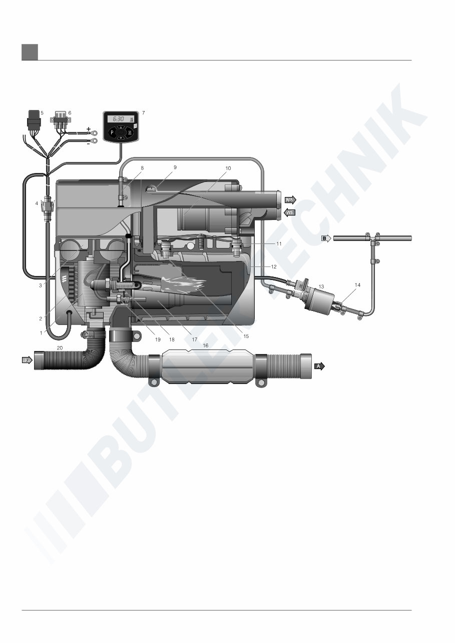
Sectional drawing HYDRONIC B 4 W SC and B 5 W SC
1 Electric motor
2 Controller
3 Combustion air fan
4 Interface / 8-pole connector
5 Fan relay
6 Fuse holder
7 Mini timer
8 Fuel connection
9 Vent screw
10 Water pump
11 Overheating sensor
12 Heat exchanger
13 Dosing pump
14 Cup filter, fitted in dosing pump
15 Temperature sensor
16 Exhaust pipe with exhaust silencer
17 Combustion chamber
18 Glow plug
19 Flame sensor
20 Combustion air pipe
A = exhaust
B = fuel
C = combustion air
WA = water discharge
WE = water intake
Function and operation 2
9
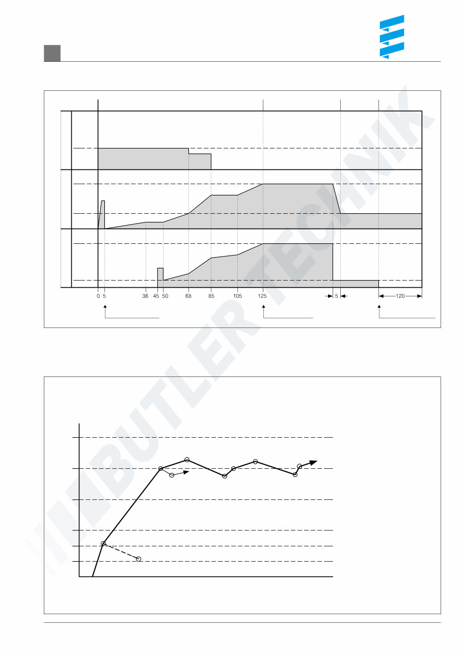
Function diagram – HYDRONIC B 4 W SC and B 5 W SC
Function and operation 2
Sectional drawing – HYDRONIC B 4 W SC and B 5 W SC
HYDRONIC on Control stage large Control stage
small
HYDRONIC off
Afterrunning on
Glow plug Fan Dosing pump
SMALL
LARGE
SMALL
LARGE
8.0 V
7.8 V
time (sec.)
Vehicle fan ON Flame detection Vehicle fan OFF
large 4.3 KW (B 4 W SC)
5.0 KW (B 5 W SC)
small 1.5 KW time
100
80
60
40
30
20
°C
large
large
large
large
off
off
Vehicle fan ON
on
on
Vehicle fan OFF
small
small
You're Reading a Preview
What's Included?
Fast Download Speeds
Online & Offline Access
Access PDF Contents & Bookmarks
Full Search Facility
Print one or all pages of your manual
$36.99
$48.99
Viewed 71 Times Today


Secure transaction
What's Included?
Fast Download Speeds
Online & Offline Access
Access PDF Contents & Bookmarks
Full Search Facility
Print one or all pages of your manual
$36.99
$48.99
Official service manual for the Eberspacher Hydronic B5WS and D5WS engine independent water heaters.
- Bookmarked chapters for easy navigation allowing you to identify exact repair service procedures in the quickest time possible.
- Notes, cautions, and warnings throughout each chapter pinpoint critical service information.
- Numbered instructions guide you through every repair procedure in a step-by-step fashion.
- Bold figured numbers help you quickly match illustrations with instructions.
- Detailed illustrations, exploded diagrams, drawings, and photos guide you through every service repair procedure.
- Numbered table of contents easy to use so that you can find the information you need fast.
Manual Language: English
File Format: .PDF
File Delivery: Instant
Pages: 52
To purchase this repair manual just click on the green instant button at the upper left-hand corner of this page. After purchasing just download it to your computer to save it and print pages from it whenever you need it.


