

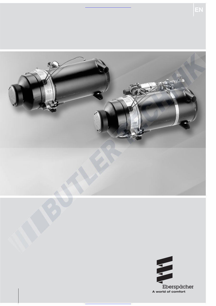
HYDRONIC 16/24/30/35
Troubleshooting and Repair Instructions
25 1818 95 20 12
12.2011
Normal version
Normal version Order No.: Basic unit No.:
Hydronic 16 – 24 Volt 25 2165 02 00 00 25 2165 01 00 00
Hydronic 24 – 24 Volt 25 1817 02 00 00 25 1817 01 00 00
Hydronic 30 – 24 Volt 25 1818 02 00 00 25 1818 01 00 00
Hydronic 35 – 24 Volt 25 1819 02 00 00 25 1819 01 00 00
Compact version Order No.: Basic unit No.:
Hydronic 24 – 24 Volt 25 1817 05 00 00 25 1817 01 00 00
Hydronic 30 – 24 Volt 25 1818 05 00 00 25 1818 01 00 00
Hydronic 35 – 24 Volt 25 2041 05 00 00 25 1819 01 00 00
Water heaters for diesel fuel, operating
perating independently of an engine.
Compact version
www.butlertechnik.com
www.butlertechnik.com
2
2
1
4
3
5
Contents
This list of contents provides precise information about the
contents of these Troubleshooting and Repair Instructions.
Introduction
If you are looking for a specific term, use the index at the end
of this document.
1
• Contents ................................................................................................... 2 – 3
• Foreword ........................................................................................................ 4
• Safety instructions for installation and repair .................................................... 4
• Accident prevention ........................................................................................ 4
• Special text structure, presentation and picture symbols ................................. 4
• Important information before starting work ...................................................... 4
• Cutaway view.................................................................................................. 5
• Structure of the heater .................................................................................... 6
• Special features of the heater .......................................................................... 6
• Operating instructions ..................................................................................... 6
• Description of functions ................................................................................... 6
• Functional diagram .......................................................................................... 7
• Control diagram .............................................................................................. 7
• Control and safety devices .............................................................................. 8
• Emergency stop (EMERGENCY OFF) .............................................................. 8
• Technical data, heater ..................................................................................... 9
• Technical data, water pump .......................................................................... 10
– Pumping and pressure loss characteristic curves ....................................... 10
• What to check first in case of faults ............................................................... 11
• Locking the control box ................................................................................. 11
• Cancelling the control box lock...................................................................... 11
• Fault diagnosis – flashing code ...................................................................... 12
• Overview of the individual test equipment and control units ........................... 13
• External diagnostic system ............................................................................ 13
• Fault diagnosis using the diagnostic unit ................................................. 14, 15
• Fault diagnosis: EDiTH customer service program with ISO adapter .............. 16
• Fault diagnosis: EDiTH customer service program with basic adapter ........... 17
• Fault diagnosis using the module timer.......................................................... 18
• Fault diagnosis using the radio remote control TP5 ....................................... 19
• Fault diagnosis with EasyStart R+ radio remote control
and EasyStart T timer .................................................................................... 20
• Fault code table .................................................................................... 21 – 24
• Repair instructions ........................................................................................ 25
• Always observe the following safety instructions before working on the heater .25
• AMP release tool ........................................................................................... 25
• Assembly drawing .................................................................................. 26, 27
– Component parts ..................................................................................... 27
• Removing the hood ....................................................................................... 28
• Dismantling the burner .................................................................................. 28
• Dismantling the control box ........................................................................... 28
• Dismantling the burner motor ........................................................................ 29
• Checking the function and speed of the burner motor
using the burner tester .................................................................................. 29
• Dismantling the ignition electrodes ................................................................ 30
• Dismantling the fuel nozzle ............................................................................ 30
• Dismantling the ignition unit ........................................................................... 31
• Testing the ignition unit using the burner tester .............................................. 31
• Dismantling the solenoid valve....................................................................... 32
• Testing the solenoid valve using the burner tester .......................................... 32
• Dismantling the nozzle block ......................................................................... 33
– Nozzle block made of brass ....................................................................... 33
– Functional check of the heating cartridge ................................................... 33
• Dismantling the flame tube ............................................................................ 34
Chapter Title Contents Page
Introduction
Function
Product information
Troubleshooting
Repair instructions
www.butlertechnik.com
www.butlertechnik.com
3
5
6
7
Introduction
1
• Dismantling the temperature and overheating sensor .................................... 35
• Temperature and overheating sensor resistance values ................................. 35
– Table of characteristic values - temperature sensor ................................... 35
– Temperature sensor diagram ..................................................................... 35
– Table of characteristic values - overheating sensor ..................................... 36
– Overheating sensor diagram ...................................................................... 36
• Dismantling the gauze fuel filter ..................................................................... 37
• Notes on the fuel flow rate and the pressure in the fuel system...................... 36
• Measuring the CO
2
content ........................................................................... 37
• Adjusting the combustion air ......................................................................... 37
• Dismantling the water pump (standard design) .............................................. 39
• "Bus 2000" water pump ................................................................................ 39
• Dismantling the FLOWTRONIC 5000 water pump ......................................... 40
• Heater circuit diagram – Part 1 (Hydronic 16 / 24 with temperature switch) ...... 41
• Heater circuit diagram – Part 1 (Hydronic 16 – 35 without temperature switch)..
42
• Heater circuit diagram – Part 2 with water pump (standard design)
and "Bus 2000" water pump ......................................................................... 43
• Heater circuit diagram – Part 3 with FLOWTRONIC water pump .................. 44
• Circuit diagram / parts list for control units............................................... 45, 46
• Parts list for circuit diagram - EasyStart control units .................................... 47
• EasyStart R control unit circuit diagram ......................................................... 48
• EasyStart R+ control unit circuit diagram ....................................................... 49
• EasyStart T control unit circuit diagram ......................................................... 50
• Certification ................................................................................................... 51
• Disposal ........................................................................................................ 51
• EC Declaration of Conformity ........................................................................ 51
• List of key words ..................................................................................... 52, 53
Chapter Title Contents Page
Repair instructions
Circuit diagrams
Service
Contents
www.butlertechnik.com
www.butlertechnik.com
4
Introduction
1
Foreword
These Troubleshooting and Repair Instructions are applicable
to the heaters listed on the title page, to the exclusion of all li-
ability claims.
Depending on the version or revision status of the heater,
there may be differences between it and these Troubleshoot-
ing and Repair Instructions.
The user must check this before carrying out the repair work
and, if necessary, take the differences into account.
Important!
Safety instructions for installation and repair!
Improper installation or repair of Eberspächer heaters can
cause a fire or result poisonous exhaust entering the inside of
the vehicle. This can cause serious and even fatal risks.
The heater may only be installed according to the specifica-
tions in the technical documents or repaired using original
spare parts by authorised and trained persons.
Installation and repairs by unauthorised and untrained per-
sons, repairs using non-original spare parts and without the
technical documents required for installation and repair are
dangerous and therefore are not permitted.
A repair may only be carried out in connection with the re-
spective unit-related technical description, installation instruc-
tions, operating instructions and maintenance instructions.
This document must be carefully read through before / dur-
ing installation and repair and followed throughout. Particular
attention is to be paid to the official regulations, the safety in-
structions and the general information.
The relevant rules of sound engineering practice and any in-
formation provided by the vehicle manufacturer are to be ob-
served during the installation and repair.
Eberspächer does not accept any liability for defects and
damage, which are due to installation or repair by unauthor-
ised and untrained persons.
Compliance with the official regulations and the safety instruc-
tions is prerequisite for liability claims. Failure to comply with
the official regulations and safety instructions leads to exclu-
sion of any liability of the heater manufacturer.
Accident prevention
General accident prevention regulations and the correspond-
ing workshop and operating safety instructions are to be ob-
served.
Special text structure, presentation and
picture symbols
Special text formats and picture symbols are used in these
instructions to emphasise different situations and subjects.
Please refer to the following examples for their meanings and
appropriate action.
Special text formats and presentations
• A dot (•) indicates a list, which is started by a heading.
– If an indented dash (–) follows a "dot", this list is a sub-
section of the black dot.
Picture symbols
Danger!
This information points out a potential serious or fatal danger.
Ignoring this information can result in severe injuries.
Important!
This information points out a dangerous situation for a person
and / or the product. Failure to comply with these instructions
can result in injuries to people and / or damage to machinery.
Important information before starting
work
Initial commissioning of the heater or functional test
after a repair
• After installing the heater, the whole fuel supply system must
be carefully vented: please refer to and follow the vehicle
manufacturer's instructions.
• During the heater trial run, all fuel connections must be
checked for leaks and secure, tight fit.
• If faults occur while the heater is running, use a diagnostic
unit to determine and correct the cause of the fault.
Please note!
www.butlertechnik.com
www.butlertechnik.com

5
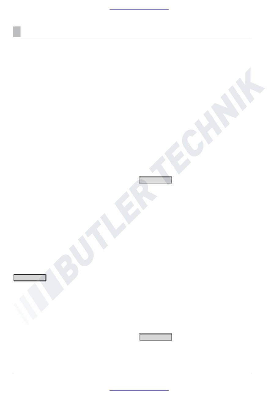
Cutaway view
A Exhaust
B Fuel
V Combustion air
WA Water outlet
WE Water inlet
Sketch 1
2
Function
1 Impeller
2 Electric motor
3 Solenoid valve
4 Flame tube
5 Control box
6 Combustion
chamber
7 Heat exchanger
8 Ignition unit
9 Ignition electrodes
10 Fuel nozzle
11 Coupling
12 Temperature sensor
13 Overheating sensor
14 Relay (vehicle blower control)
15 Fuses
16 Module timer
17 Water pump
18 Exhaust pipe
19 Fuel connection
20 Hood (CO
2
adjustment)
21 Flame detection photocell
22 Nozzle block with integrated heating
element
www.butlertechnik.com
www.butlertechnik.com
6
Structure of the heater
The heater consists of a heat exchanger and a removable
burner. A combustion chamber consisting of a flame tube with
integrated mixer is inserted in the heat exchanger. The flame
tube can be pulled out of the heat exchanger if necessary.
The control box and electric motor are fixed to the burner
flange under the burner hood. The fuel pump is integrated in
the burner housing.
The following additional parts are required for operation of the
heater:
• Water pump
• Additional parts for connection to the water circuit
• Additional parts for the fuel supply
• Additional parts for the exhaust system
• Control unit
Order No. see technical description, for further additional parts
see additional parts catalogue.
Special feature of the heater
• If the water flow rate is too low, the water outlet temperature
is limited by premature correction.
• The temperature rise of the heating medium is monitored
over time. If it rises too fast (water flow rate too low) the
heater automatically switches "OFF" and begins the after-
run, the cycle then begins again.
• Constant comparison of the measured temperature sensor
and overheating sensor values provides additional heater
safety. If the difference between the measured values is
too large (water flow rate too low) the heater prematurely
switches "OFF".
Operating instructions
The heater is operated by a control unit. Detailed operating in-
structions are supplied with the control unit.
The operating instructions are issued to you by the garage /
workshop that installs the heater.
Please note!
Description of functions
Switching on the heater
When the heater is switched on, a component test is carried
out (3 seconds) and then the water pump is started up.
Note:
If the water temperature is < 5 °C the nozzle pre-heater is
switched on for 60 seconds; the burner start is delayed by
this length of time.
Burner start
The electric motor starts and drives the combustion air impel-
ler and the fuel pump.
After approx. 10 seconds, the ignition is switched on and then
the fuel solenoid valve opens. Within these 10 seconds a ro-
tational check of the electric motor is carried out. The fuel and
combustion air in the combustion chamber form an ignitable
mixture.
The mixture is ignited by a high-voltage ignition spark. The
flame detection photocell detects the flicker frequency of the
flame and switches off the ignition unit. The hot fuel gases
flow through the heat exchanger and transfer the heat to the
heating medium.
• The heater operates depending on the heat requirement,
therefore the length of the burner's on-time and off-time
periods differ.
• The water pump continues to run throughout the whole op-
erating period, even during pause mode periods and during
the after-run.
Options
• When the temperature drop is activated the "ON / OFF"
control temperatures are lowered by approx. 8K.
For connection of the ON / OFF switch for temperature
drop, see circuit diagram on pages 43 and 44.
• The water pump can also be operated independently of the
heater, if an appropriate control is installed. For connec-
tion of the additional "ON / OFF" switch for separate water
pump control, see circuit diagram on pages 43 and 44.
• For vehicle blower control, the vehicle blower is switched on
and off at the following water temperatures.
– Water temperature > 55 °C —>Vehicle blower "ON"
– Water temperature < 50 °C —>Vehicle blower "OFF"
Switching off the heater
If the heater is switched off, the fuel solenoid valve closes and
at the same time the approx. 3 minute after-run begins.
After the after-run has finished the heater is automatically
switched off.
Until it is switched off, including during the after-run, the fuel is
circulated.
Please note!
Please note!
Function
2
www.butlertechnik.com
www.butlertechnik.com
7
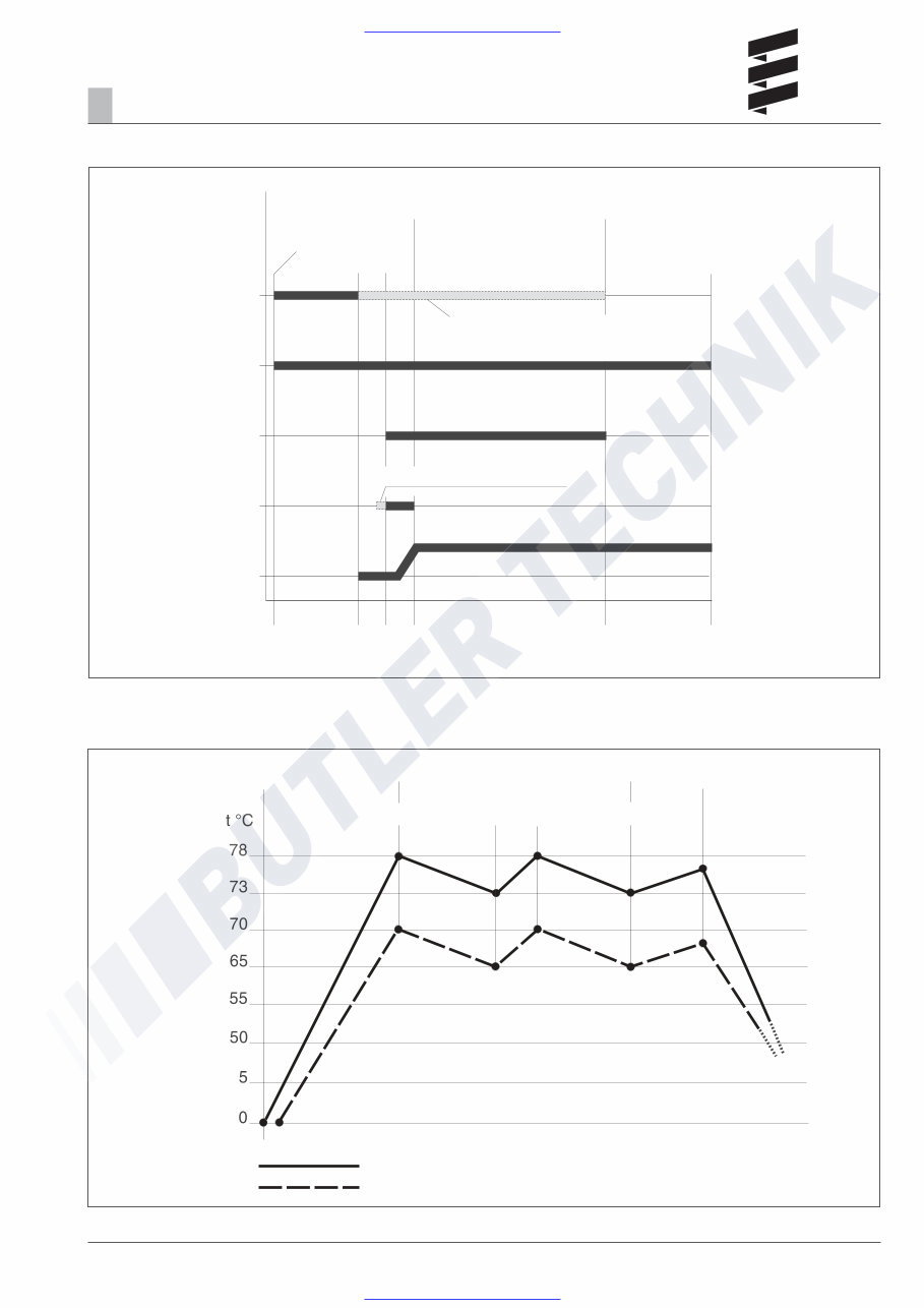
Control diagram
Functional diagram
Sketch 2
Sketch 3
Function
2
Heater ON
Heating mode
Heater OFF
After running
Components test
Nozzle block heating
(ON at temperature <5 °C)
Water pump
Solenoid valve
Ignition unit
Electric motor
From control box 25 1818 53 00 00
From control box 25 1818 53 00 00,
switching "OFF / ON" of the nozzle block
heating is temperature controlled
3 sec.
60 sec.
10 sec.
10 sec.
180 sec.
Heater ON NORMAL OPERATION Heater OFF
After-run – 3 min.
Control – Normal
Control – Temperature drop
ON ON OFF OFF
Vehicle blower ON
Vehicle blower OFF
www.butlertechnik.com
www.butlertechnik.com

8
Function
2
Control and safety devices
The heater is equipped with the following control and safe-
ty devices.
• If the heater does not ignite the control box* is locked after
an impermissible number of failed start attempts.
• If the water flow rate is too low, the water outlet temperature
is limited by premature correction.
• The temperature rise of the heating medium is monitored
over time. If it rises too fast (water flow rate too low) the
heater automatically switches "OFF" and begins the after-
run, the cycle then starts again.
• Constant comparison of the measured values for the tem-
perature sensor and overheating sensor provides additional
heater safety, as a premature lockout (shutdown on faults)
occurs if the difference between the measured values is too
high (the water flow rate is too low).
After an impermissible number of lockouts, the control box
is locked.*
• If the lower or upper voltage limit is reached, a lockout
(shutdown on faults) occurs.
• If the flame sensor detects a flame during the heater's after-
run a lockout occurs (shutdown on faults).
After an impermissible number of lockouts, the control box
is locked.*
* The lock can be cancelled and the faults read out:
• with the module timer / EasyStart T timer
• with the radio remote control TP5 / EasyStart R+.
For other control units by connecting:
• the diagnostic unit
• the customer service program KD2000 / EDiTH.
For details of operation and fault list, see these Trouble-
shooting and Repair Instructions from page 13.
Emergency shutdown – EMERGENCY
OFF
If an emergency shutdown –
EMERGENCY OFF – is required during operation, execute
the following:
• Switch the heater off at the control unit or
• remove the fuse or
• disconnect the heater from the battery.
www.butlertechnik.com
www.butlertechnik.com
9
Product information
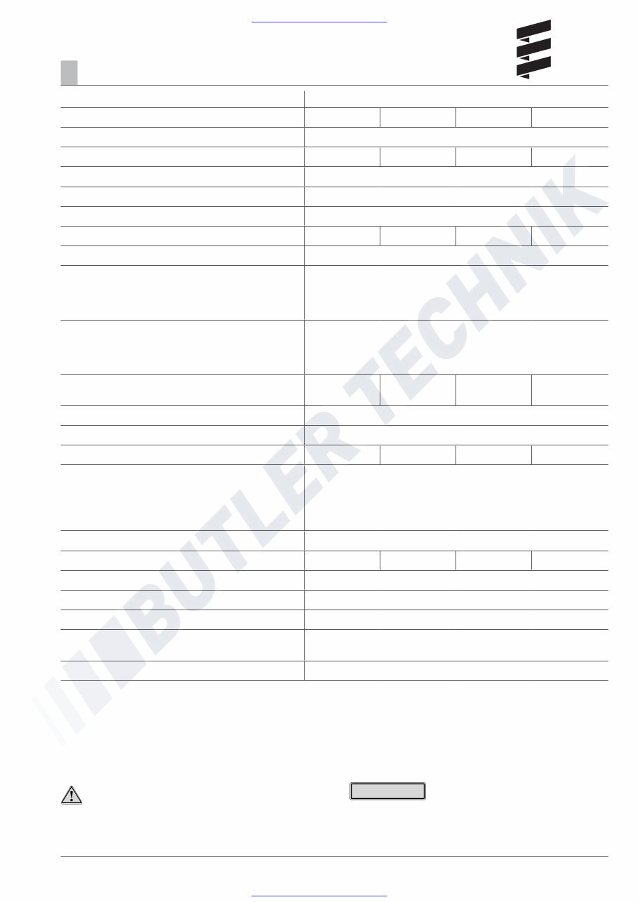
Technical data, heater Hydronic L
Type D 16 W N D 24 W N D 30 W N D 35 W N
Heating medium Mixture of water and refrigerant (max. 50 % refrigerant fraction)
Heat flow in watt (at ambient temperature 20 °C) 16 000 24 000 30 000 35 000
Temperature values – at water inlet ON 73 °C / OFF 78 °C
Temperature values – at water outlet ON 85 °C / OFF 118 °C
Fuel Diesel – standard commercial (DIN EN 590) Heating oil EL (DIN 51603)
Fuel consumption (at ambient temperature –10 °C) 2.0 l/h 2.9 l/h 3.65 l/h 4.2 l/h
Rated voltage 24 volt
Operating range
• Lower voltage limit:
An undervoltage protector installed in the control box
switches off the heater if the voltage limit is reached.
19 volt
• Upper voltage limit:
An overvoltage protector (surge suppressor) installed
in the control box switches off the heater if the voltage
limit is reached.
30 volt
Electrical power consumption
(in combustion mode / without circulating pump)
60 watt 80 watt 105 watt 120 watt
Water content of the heat exchanger approx 2 l
Water content of the water circuit min. 10 l
Minimum heating medium flow rate (±200 l/h) 1400 l/h 2000 l/h 2600 l/h 3000 l/h
Permissible ambient temperature in operation:
during transport / storage:
for the combustion air:
Pumped medium:
–40 °C to +85 °C
–40 °C to +100 °C
< 60 °C
–40 °C to +90 °C,
short-term up to +120 °C
Operating pressure (water circuit) < 2.5 bar
CO
2
values (% vol) 9 – 11 9 – 11 9 – 11 9.5 – 11.5
CO in the exhaust < 0.04
Smoke spot no. (Bacherach) < 4
Weight approx 18 kg
Interference suppression class VHF 4 / SW 3 / MW 5 / LW 3 according to DIN 57879 / Part 1
VDE 0879
Protection IP 64
3
If no limit values are given, the technical data listed is with the
usual heater tolerances of ± 10 % at nominal voltage, 20 °C
ambient temperature and Esslingen reference altitude.
Please note!
Important!
Safety instructions for technical data!
Failure to comply with the technical data can result in malfunc-
tions.
www.butlertechnik.com
www.butlertechnik.com
10
Product information
3
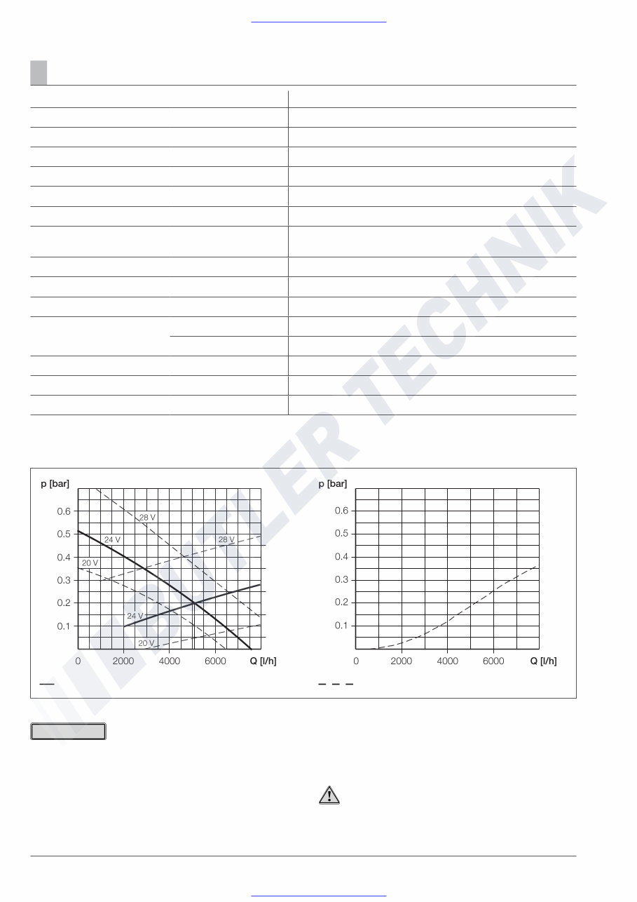
Technical data, water pump FLOWTRONIC 5000
Heating medium Mixture of water and refrigerant (max. 50 % refrigerant fraction)
Delivery rate 5200 l/h ±10 % at 0.2 bar discharge pressure
Water circuit operating pressure max. 2 bar
Weight (without bracket, clamp and refrigerant) 2.14 kg
Rated voltage 24 volt
Operating range 20 – 28 volt
Power consumption at 5200 l/h and 0.2 bar discharge pres-
sure
104 watt ±10 %
Interference suppression class 3 according to DIN 57879 / Part 1 VDE 0879
Protection IP 54A according to DIN 40 050 Sheet 1
Electrical fusing for third party control 15 A
Temperature conditions Heating medium –40 °C to + 90 °C [short-term (15 min.) +115 °C]
–40 °C to 90 °C [short-term (15 min.) +115 °C] Ambient, operation
Dry running No
Blocking Within a period of max. 6 seconds the motor is undamaged.
Shaft - impeller connection Mechanical seal
Pumping and pressure loss characteristic curves
• If no limit values are given, the technical data listed is with
the usual heater tolerances of ± 10 % at nominal voltage,
20 °C ambient temperature and Esslingen reference alti-
tude.
• The FLOWTRONIC 5000 water pump is installed in com-
pact design heaters.
• If water pumps are ordered separately, please refer to the
documentation supplied with them for the relevant technical
data, installation positions, etc.
Flow resistance (when pump at rest) Volumetric flow rate (with water at 20 °C)
Please note!
Important!
Safety instructions for technical data!
Failure to comply with the technical data can result in malfunc-
tions.
Sketch 4
www.butlertechnik.com
www.butlertechnik.com
You're Reading a Preview
What's Included?
 Lifetime Access
Fast Download Speeds
Online & Offline Access
Access PDF Contents & Bookmarks
Full Search Facility
Print one or all pages of your manual
$36.99
Eberspacher Hydronic 16, 24, 30 and 35 water heater service manual
Viewed 73 Times Today

What's Included?
Lifetime Access
Fast Download Speeds
Online & Offline Access
Access PDF Contents & Bookmarks
Full Search Facility
Print one or all pages of your manual
$36.99

Secure transaction
What's Included?
Lifetime Access
Fast Download Speeds
Online & Offline Access
Access PDF Contents & Bookmarks
Full Search Facility
Print one or all pages of your manual
Description
Official service manual for the Eberspacher Hydronic 16, 24, 30 and 35 water heaters.
- Book marked chapters for easy navigation allowing you to identify exact repair service procedures in the quickest time possible.
- Notes, cautions and warnings throughout each chapter pinpoint critical service information.
- Numbered instructions guide you through every repair procedure in a step-by-step fashion.
- Bold figured numbers help you quickly match illustrations with instructions.
- Detailed illustrations, exploded diagrams, drawings and photos guide you through every service repair procedure.
- Numbered table of contents easy to use so that you can find the information you need fast.
Manual Language: English
File Format: .PDF
File Delivery: Instant
Pages: 55
To purchase this repair manual just click on the green instant button at the upper left hand corner of this page. After purchasing just save it to your computer to save it and print pages from it whenever you need it.


