

1990 Maytag Washer Service & Repair Manual
What's Included?
Fast Download Speeds
Online & Offline Access
Access PDF Contents & Bookmarks
Full Search Facility
Print one or all pages of your manual

16023083
© 1996 Maytag Corporation
INTRODUCTION
The information presented in this manual is printed in a loose format and is divided into
sections relating to a general group of components and/or service procedures. Each
section is further subdivided to describe a particular component or service procedure.
Anything of a unique nature concerning these models has been detailed and labeled as
such in the manual.
The subdividing of the subject matter, plus the loose leaf form will facilitate the updat-
ing of the manual as new or revised components are added or new models are intro-
duced.
Each page of the manual will be identified in the lower right-hand corner, and as new or
revised pages are published, the manual can easily be updated by following the file
instructions on the cover letter of the supplement.
The service manual is a valuable tool and care should be taken to keep it up to date by
prompt and proper filing of subsequent pages as they are used.
MODELS COVERED IN THIS MANUAL
PAV1000AW*
PAV2000AW*
INTRODUCTION i
DLW231*
PAV2300*
PAV3300*
PAV5000*
PAV5157*
PAV5158*
PAVT344*
HAV2460*
PAVT244*
PAVT234*
HAV2360*
MAV2200*
HAV2557*
HAV2558*
HAV3460*
PAVT444*
HAV4657*

16023083
© 1996 Maytag Corporation
INTRODUCTION ii

16023083
© 1996 Maytag Corporation
CONTENTS iii
SECTION 1. INSTALLATION ............................................................... 1-1
PRE-INSTALLATION REQUIREMENT .......................................................................... 1-1
Water Supply Requirements .................................................................................. 1-1
Drain Requirements ................................................................................................ 1-1
Electrical Requirements .......................................................................................... 1-2
INSTALLATION PROCEDURE ...................................................................................... 1-2
SECTION 2. OUTLINE OF MECHANICAL OPERATION ................... 2-1
CLUTCH ASSEMBLY ................................................................................................... 2-1
AGITATION .................................................................................................................. 2-2
SPIN ............................................................................................................................. 2-2
SECTION 3. CABINET ASSEMBLY COMPONENTS ......................... 3-1
CABINET BODY ASSEMBLY ...................................................................................... 3-1
Front Panel ............................................................................................................. 3-1
Rear Access Panel ................................................................................................. 3-2
TOP ASSEMBLY .......................................................................................................... 3-3
DOOR ASSEMBLY ...................................................................................................... 3-4
CONTROL PANEL ASSEMBLY (PAV1000AWW, PAV2000AWW) ............................ 3-4
Disassembly ........................................................................................................... 3-4
CONTROL PANEL ASSEMBLY (PAV2200, 3200, 4200) ............................................. 3-6
Disassembly ........................................................................................................... 3-6
BASE ASSEMBLY ....................................................................................................... 3-8
STABILIZER ASSEMBLY ............................................................................................. 3-9
SECTION 4. WATER RELATED COMPONENTS ................................ 4-1
WATER MIXING VALVE .............................................................................................. 4-2
WATER INLET FLUME .................................................................................................. 4-3
AIR BELL ...................................................................................................................... 4-3
HOSES ......................................................................................................................... 4-3
TUB TOP ...................................................................................................................... 4-4
AGITATOR (PAV1000AWW, PAV2000AWW) ............................................................ 4-4
AGITATOR (PAV2200, 3200, 4200) ............................................................................. 4-5
SPIN BASKET .............................................................................................................. 4-5
OUTER TUB ASSEMBLY ............................................................................................. 4-6
PUMP ASSEMBLY ....................................................................................................... 4-7
SECTION 5. SUSPENSION SYSTEM (PAV1000AWW, PAV2000AWW) ... 5-1
SUSPENSION SYSTEM (PAV2200, 3200, 4200) ........................................................ 5-2
SUSPENSION HOUSING ............................................................................................. 5-3
TUB BRACES ............................................................................................................... 5-3
SUSPENSION SPRINGS .............................................................................................. 5-3
CONTENTS

16023083
© 1996 Maytag Corporation CONTENTS iv
SECTION 6. TRANSMISSION AND RELATED COMPONENTS ........ 6-1
CENTER POST ASSEMBLY ........................................................................................ 6-2
BEARING AND SEAL HOUSING .................................................................................. 6-2
TUB SEAL .................................................................................................................... 6-3
SPIN BEARING ............................................................................................................. 6-4
DRIVE PULLEY AND CAMS ........................................................................................ 6-5
BRAKE ASSEMBLY ..................................................................................................... 6-8
TRANSMISSION HOUSING ASSEMBLY ..................................................................... 6-10
Oil Seal Replacement ............................................................................................ 6-11
LOWER BEARING ASSEMBLY .................................................................................. 6-11
DIAGNOSING TRANSMISSION PROBLEMS ............................................................. 6-13
SECTION 7. ELECTRICAL COMPONENTS AND TESTING .............. 7-1
TIMER ........................................................................................................................... 7-1
TIMER SEQUENCE CHART ......................................................................................... 7-2
MOTOR ........................................................................................................................ 7-3
MOTOR SWITCH ........................................................................................................ 7-3
MOTOR MOUNTING .................................................................................................... 7-6
MOTOR CIRCUIT TESTING ......................................................................................... 7-7
Overload Protector ................................................................................................ 7-7
Motor Switch ........................................................................................................... 7-8
Motor ...................................................................................................................... 7-8
WATER MIXING VALVE .............................................................................................. 7-8
WATER LEVEL SWITCH .............................................................................................. 7-9
SELECTOR SWITCHES ............................................................................................. 7-11
SAFETY SPIN SWITCH ............................................................................................. 7-11
SECTION 8. SCHEMATIC DIAGRAM ................................................... 8-1
SECTION 9. TROUBLESHOOTING ...................................................... 9-1

16023083
© 1996 Maytag Corporation
SAFETY NOTES
PRECAUTIONS TO BE OBSERVED BEFORE AND DURING SERVICING TO AVOID
POSSIBLE EXPOSURE TO EXCESSIVE DANGER AND ELECTRICAL SHOCK:
1. Disconnect electrical supply before servicing machine.
2. If electricity is required for a test:
(A) First, disconnect electrical supply;
(B) Second, make any connections or adjustments required for the test;
(C) Third, connect electrical supply;
(D) Fourth, perform the test. If service is required, disconnect electrical
supply before servicing machine.
3. Please use caution when servicing the machine with the front panel
removed because there is danger of injury due to potential contact
with spinning transmission.
4. Please use caution when servicing the machine with the front panel
removed because there is danger of injury due to contact with a
potential "pinch point" between the turned up edge of the transmission
cover and the tub support flange.
SAFETY NOTES v

16023083
© 1996 Maytag Corporation
SAFETY NOTES vi
16023083
© 1996 Maytag Corporation
WASHER WEIGHT
Shipping - 185 pounds approximately
Operating - 160 pounds approximately
DIMENSIONS
Width 27"
Depth 27"
Height to top of cabinet 35 3/4"
Height to top of control panel 44"
Height with door open 53 1/2"
FINISH
Cabinet Top - powdered paint
Clothes Door - powdered paint
Outer Tub - constructed entirely of polypropylene
Basket - polypropylene
Cabinet - baked enamel
Base and other finished parts - baked primer
DRAIN HEIGHT
32 inch minimum
60 inch minimum
MOTOR
3/4 H.P., reversible, 115 volt, 60 cycle A.C.
TRANSMISSION
Rack and pinion type, incorporating reduction gears
SPECIFICATIONS
SPECIFICATIONS Vii
16023083
© 1996 Maytag Corporation
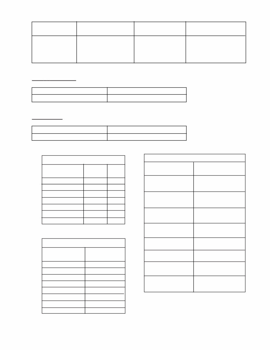
WATER
CYCLE LEVEL *AMPS
Agitate-Regular Full Tub 10.4
Agitate-Slow Full Tub 7.6
Agitate-Regular Dry Tub 7.5
Spin-Regular Dry Tub 10.2
Spin-Slow Dry Tub 7.6
Pump Out-Regular Full Tub 10.8
Pump Out-Slow Full Tub 8.0
Setting Gallons *Depth *Basket
Inches Perforations
Mini 10.5 6" 3 1/2"
Medium 14.1 8 1/2" 5"
High 19.5 11" 7"
Super 23.3 13 1/2" 9 1/4"
*Allowable variations are plus or minus 1/2 inch.
AGIT A T OR SPEED
Regular Cycle 90 Oscillations per minute
Slow (Delicate) Cycle 60 Oscillations per minute
SPIN SPEED
Regular Cycle 625 R.P.M.
Slow (Fine Wash) Cycle 416 R.P.M.
SPECIFICATIONS viii
*WATTAGE
CYCLE RANGE
Agitate-Regular
Full Tub 610-640 / 670 (MAX.)
Agitate-Slow
Full Tub 370-400 / 420 (MAX.)
Agitate-Regular
Dry Tub 460-470 / 480 (MAX.)
Agitate-Slow
Dry Tub 350-360 / 370 (MAX.)
Pump Out-Regular 760
Pump Out-Slow 510
Spin-Regular
Full Tub 460
Spin-Slow
Full Tub 340
* These will vary with washer load and line voltage.
TABLE 0-1. AMPERAGE CHART
TABLE 0-2. RESISTANCE CHART
TABLE 0-2. RESISTANCE CHART
*RESISTANCE
COMPONENTS (OHMS)
Timer Motor 2360
Mixing Valve
Cold Solenoid 853
Hot Solenoid 867
Drive Motor
High Speed 1.3
Low Speed 2.3
Start 3.1
* These values can vary slightly.
You're Reading a Preview
What's Included?
Fast Download Speeds
Online & Offline Access
Access PDF Contents & Bookmarks
Full Search Facility
Print one or all pages of your manual
$28.99
Viewed 74 Times Today


Secure transaction
What's Included?
Fast Download Speeds
Online & Offline Access
Access PDF Contents & Bookmarks
Full Search Facility
Print one or all pages of your manual
$28.99
The Factory Repair Manual is the perfect resource for both professional mechanics and DIY enthusiasts. This comprehensive manual covers everything you need to fix your Maytag washer model 1990. Whether you're using a Windows or Mac computer, this manual is compatible with both platforms. With this manual, you can print out any pages you need to assist you in repairing your washer. Say goodbye to expensive repair costs and take control of the repair process yourself. Securely purchase the manual using PayPal or your credit card.


