LG WM3570H WM3570HWA WM3570HVA Service Manual and Repair Guide
What's Included?
Lifetime Access
Fast Download Speeds
Online & Offline Access
Access PDF Contents & Bookmarks
Full Search Facility
Print one or all pages of your manual
WASHING MACHINE SERVICE MANUAL CAUTION READ THIS MANUAL CAREFULLY TO DIAGNOSE PROBLEMS CORRECTLY BEFORE SERVICING THE UNIT. MODEL: WM3570H*A Website : http://biz.lgservice.com 1
CONTENTS 1. Specifications .................................................................................................................................. 3 2. Features and Technical Explanation ............................................................................................ 4-6 3. Parts Identification ........................................................................................................................... 7 4. Installation and Test ................................................................................................................... 8-10 5. Operation ................................................................................................................................. 11-17 5-1. Control Panel Features ..................................................................................................... 11-13 5-2. Cycle Guide ........................................................................................................................... 14 5-3. Special Functions ................................................................................................................... 15 5-4. Explanation of Each Process ............................................................................................ 16-17 6. Wiring Diagram / Program Chart ................................................................................................... 18 7. Test Mode ...................................................................................................................................... 19 7-1. Safety Caution ....................................................................................................................... 19 7-2. Load Test Mode ..................................................................................................................... 19 7-3. How To Read the Display in Load Test Mode ........................................................................ 19 8. Troubleshooting ............................................................................................................................ 20 8-1. Safety Caution ....................................................................................................................... 20 8-2. Error Mode Summary ....................................................................................................... 20-21 8-3. Troubleshooting With Error ............................................................................................... 22-28 8-5. Before using the Tag On function .......................................................................................... 34 8-4. Troubleshooting Else ........................................................................................................ 29-33 9. Component Testing Information .................................................................................................... 35 9-1. Filter Assembly (Line Filter) ................................................................................................... 35 9-2. Door Look Switch Assembly ............................................................................................. 36-37 9-3. Stator Assembly ................................................................................................................ 38-40 9-4. Pump Motor Assembly ........................................................................................................... 42 9-5. Inlet Valve Assembly .............................................................................................................. 43 9-6. Heater Assembly .................................................................................................................... 44 9-7. Thermistor Assembly ........................................................................................................ 45-45 10. Disassembly Instructions ......................................................................................................... 46-54 11. Exploded View ......................................................................................................................... 55-57 11-1. Cabinet and Control Panel Assembly ................................................................................... 55 11-2. Drum and Tub Assembly ...................................................................................................... 56 11-3. Dispenser Assembly ............................................................................................................. 57 2
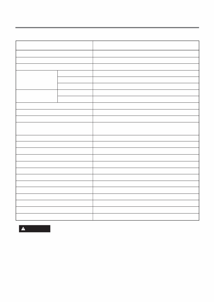
1. SPECIFICATIONS WM3570H*A M E T I COLOR POWER SUPPLY PRODUCT WEIGHT CYCLES WASH/RINSE TEMPERATURES SPIN SPEEDS OPTIONS WATER CIRCULATION OPERATIONAL WATER PRESSURE CONTROL TYPE WASH CAPACITY [cu.ft. ] DIMENSIONS DELAY WASH DOOR SWITCH TYPE WATER LEVEL LAUNDRY LOAD SENSING ERROR DIAGNOSIS AUTO POWER OFF CHILD LOCK STEAM ELECTRIC POWER CONSUMPTION REVOLUTION SPEED WASHING DRAIN MOTOR WASH HEATER WASH SPIN 12 5 5 Steam, Pre Wash, Delay Wash, Custom PGM, Fresh Care, PGM Save, Turbo Wash, Cold Wash, Extra Rinse, Rinse+Spin Incorporated 14.5 – 142 PSI(100 – 980kPa) Electronic (4.3 DOE) 27”(W) X 29 3 /4”(D) X 38 11 /16”(H), 51”(D, door open) up to 19 hours PTC + Solenoid 10 steps (by sensor) Incorporated Incorporated Incorporated Incorporated Incorporated 240 W 80 W 1000 W 46 rpm 0-1,300 rpm Blue White, VCM AC 120 V, 60 Hz 202.8lb (92kg) To reduce the risk of injury to persons, adhere to all industry recommended safety procedures including the use of long sleeved gloves and safety glasses. Failure to follow all of the safety warnings in this manual could result in property damage, injury to persons or death. WARNING 3
2.FEATURES & TECHNICAL EXPLANATION 2-1. FEATURES Ultra Capacity The larger drum enables not just higher head drop and stronger centrifugal force, but also less tangling and wrinkling of the laundry. Heavier loads, such as king size comforters, blankets, and curtains, can be washed. Direct Drive System The advanced brushless DC motor directly drives the drum without belt and pulley. Tilted Drum and Extra Large Door Opening Tilted drum and extra large opening make it possible to load and unload clothing more easily. Steam Washing Steam washing features upgraded washing performance with low energy and water consumption. Automatic Wash Load Detection Automatically detects the load and optimizes the washing time. Built-in Heater Internal heater helps to maintain water temperature at its optimum level for selected cycles. Child Lock The child lock prevents children from pressing any button to change the settings during operation. 4
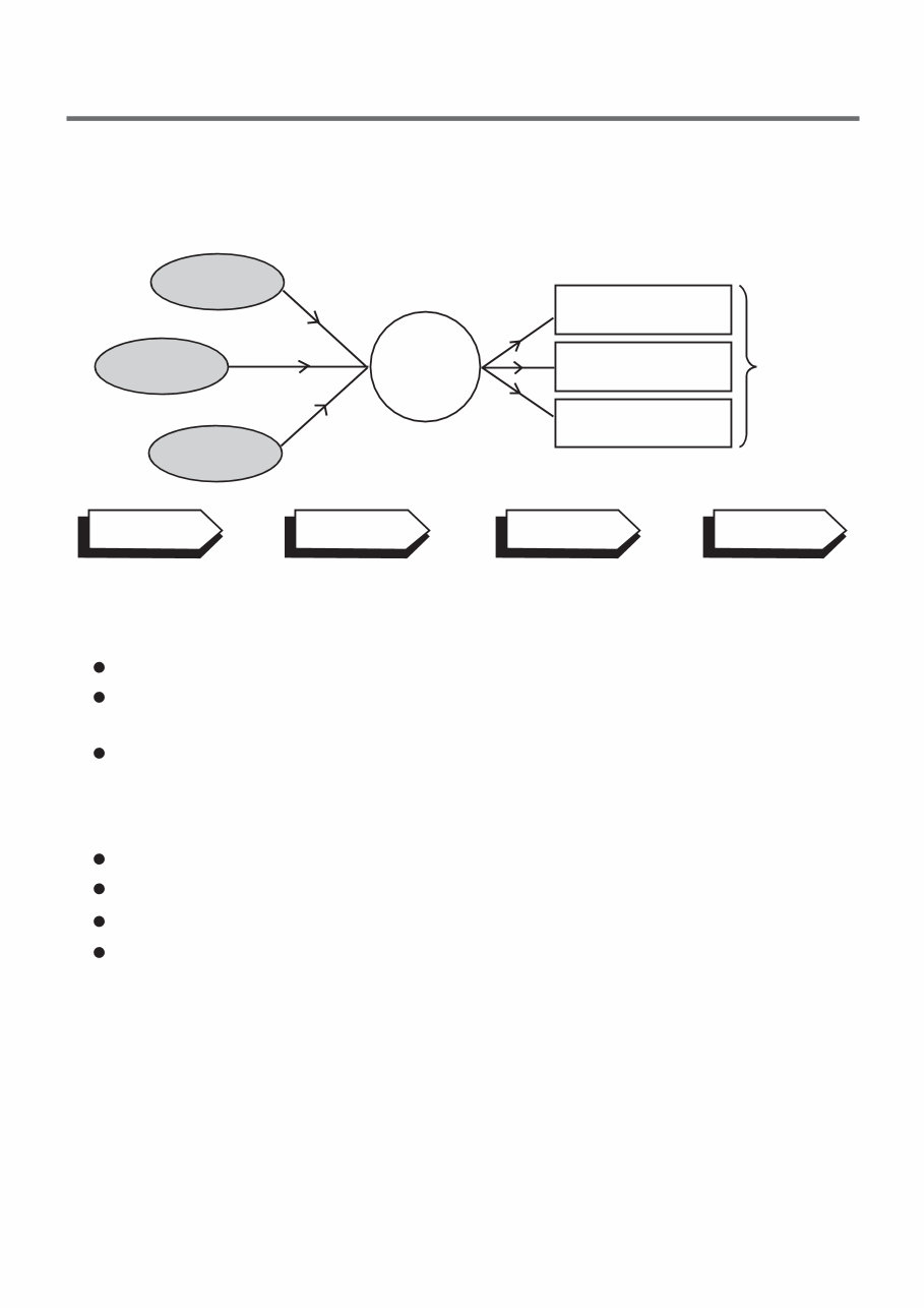
2-2. NEURO FUZZY WASHING TIME OPTIMIZATION To get the best washing performance, optimal time is determined by the water temperature, the selected washing temperature, and the size of the load. 2-3. WATER LEVEL CONTROL This model incorporates a pressure sensor which can sense the water level in the tub. The water supply is stopped when the water level reaches the preset level, the washing program then proceeds. Spinning does not proceed until the water in the tub drains to a certain level. water temperature washing time rinsing time the best washing performance spin rhythm, time load size NEURO- FUZZY selected washing temperature SENSING EFFECT PROCESSING DETERMINATION The door can be opened by pulling the door handle whenever washer is not in operation. When the cycle is completed, the DOOR LOCKED light will turn off. If a power failure has occurred while in operation, the door will unlock after 5 minutes. Clicking sounds can be heard when the door is locked/unlocked. 2-4. DOOR CONTROL 5
2-5. THE DOOR CAN NOT BE OPENED While program is operating. When a power failed and power plug is taken out in operation. While Door Lock lights turn on. White the motor is in the process of inertial rotating, through the operation is paused. 2-6. DOOR LOCKED LAMP LIGHTS When the frequency of water level is lower than 22.9 kHz. (It can be canceled when the frequency is more than 23.8 kHz.) When the temperature inside the tub is higher than 45°C and water level is not 25.5 kHz. (It can be canceled when the water level is 25.5 kHz or the temperature inside the tub is lower than 40°C.) 2-7. CHILD LOCK Use this option to prevent unwanted use of the washer. Press and hold Pre Wash button for 3 seconds to lock/unlock control. When child lock is set, CHILD LOCK lights and all buttons are disabled except the POWER button. You can lock the controls of the washer while washing. CHILD LOCK lasts after the end of cycle. If you want to deactivate this function, Press and hold the Pre Wash button for 3 seconds. 2-8. WATER CIRCULATION When washing and rinsing function of shower at the upper part of Gasket. When washing, it continuously operates for 3 minutes and intermittently. When rinsing, it continuously operates after completion of water supply. 2-9. STEAM For tough stained clothes, sick room linens, or baby clothes. Steam Wash is available with Sanitary, Bulk/Large, Perm. Press, Cotton/Normal cycles. This option features upgraded washing performance with low energy and water consumption. Do not load delicates such as wool, silk, and easily discolored clothes. 6
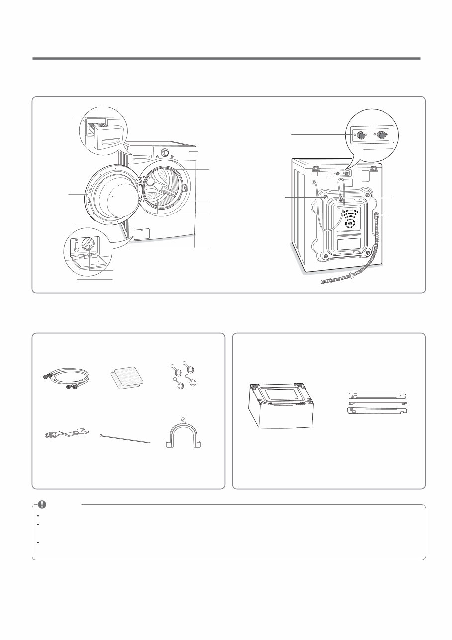
3.PARTS IDENTIFICATION NOTE Contact LG Customer Service at 1-800-243-0000 (1-888-542-2623 in Canada) if any accessories are missing. For your safety and for extended product life, use only authorized components. The manufacturer is not responsible for product malfunction or accidents caused by the use of separately purchased unauthorized components or parts. The images in this guide may be different from the actual components and accessories, and are subject to change by the manufacturer without prior notice for product improvement purposes. Parts and Accessories Parts Pedestal (sold separately) Stacking Kit (sold separately) Accessories Hot/cold water hoses Non-skid pads Caps for covering shipping bolt holes Wrench Tie strap Elbow bracket (for securing drain hose) Water inlets Shipping bolts Power cord Drain hose INCLUDED Accessories OPTIONAL Accessories Detergent dispenser drawer Door Magnet Door Plunger Control panel Door seal TurboWash™ Upper Nozzle Tub Leveling feet Drain pump filter cover Drain pump filter Drain hose 7
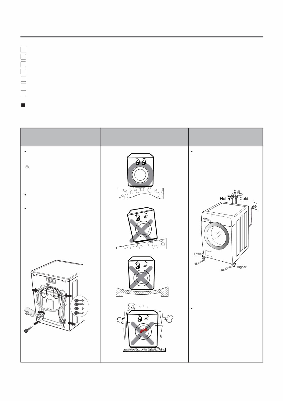
1 2 3 4 5 6 7 Before servicing, ask the customer what the trouble is. When installing or repairing the washer, put on long gloves and safety glasses. Check the setup (power supply is 120 VAC, remove the transit bolts, level the washer, etc.) Check with the troubleshooting guide. Plan your service method by referring to the disassembly instructions. Service the unit. After servicing, operate the appliance to see whether it functions correctly. STANDARD INSTALLATION The appliance should be installed as follows: Remove the 4 shipping bolts with the supplied wrench. Remove the lower bolts fist. It is easier that way. Keep the shipping bolts and spanner for future use. Insert the 4 caps (provided) into the hole. Turn clockwise to raise; counterclockwise to lower. Turn the leveling feet to adjust the appliance. REMOVE THE SHIPPING BOLTS INSTALL THE APPLIANCE ON A FLAT AND FIRM SURFACE ADJUST THE LEVELING 4.INSTALLATION & TEST Keeping 8
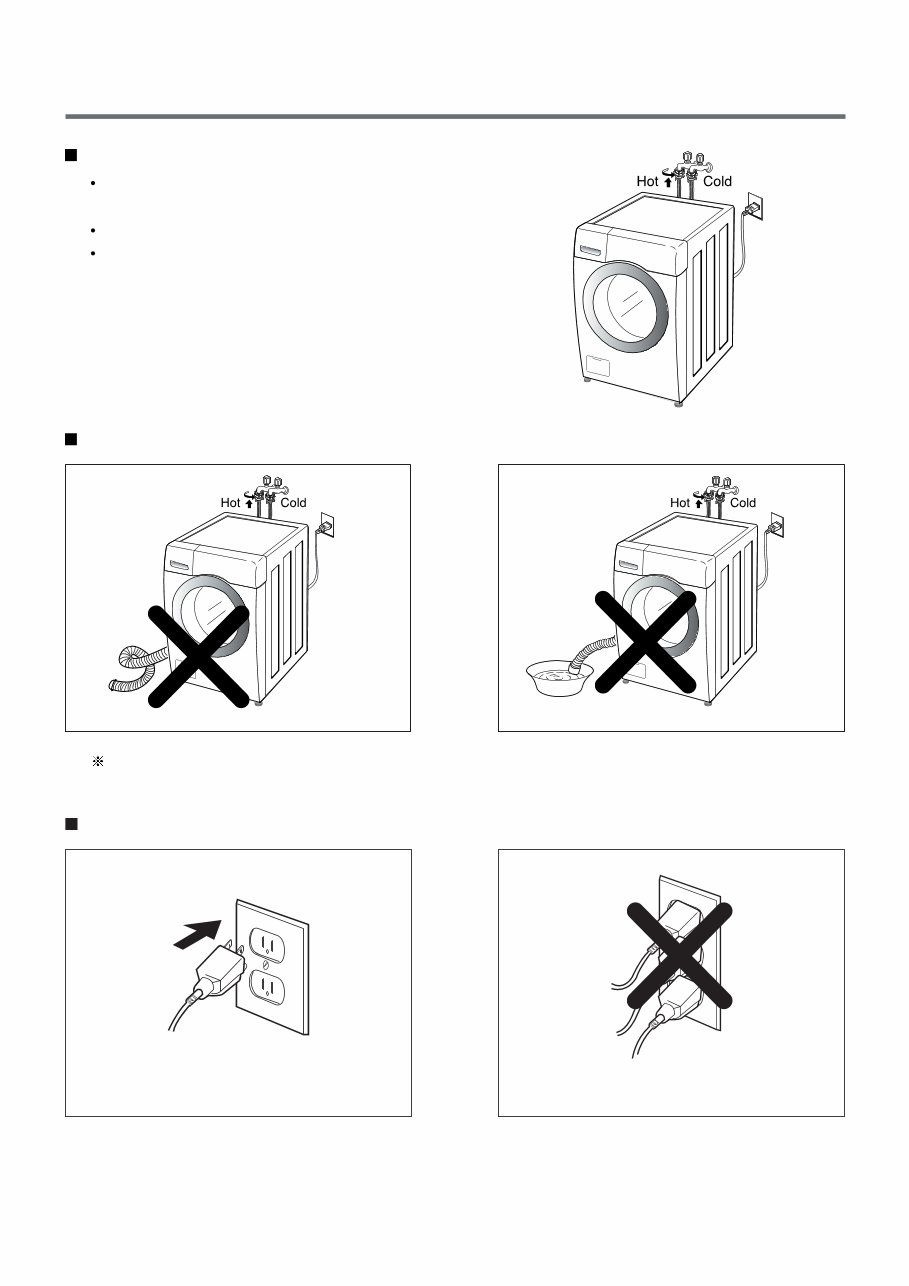
CONNECT POWER PLUG • Connect the power plug to the wall outlet. • Avoid connecting several electric devices, as doing so may cause a fire. Verify that the rubber washer is inside of the valve connector. Tighten the inlet hose securely to prevent leaks. Install the inlet hose to correct temperature water tap. Otherwise, it cause drips on the drawer panel handle and drawer panel. HOW TO CONNECT THE INLET HOSE CONNECT THE DRAIN HOSE • Make sure that the hose is not twisted. The end of the drain hose should be placed less than 96” from the floor. • Avoid submerging the end of the hose. 9
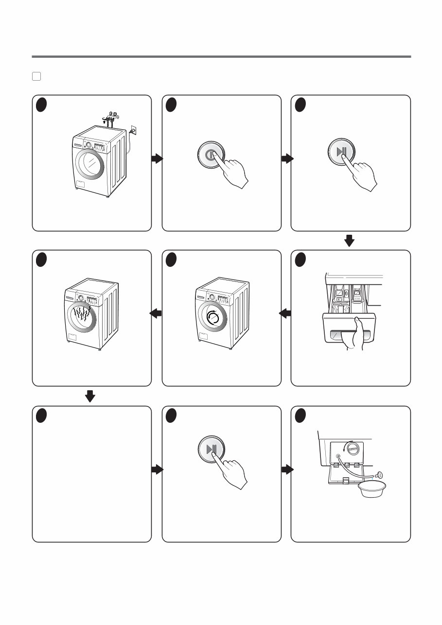
7 TEST OPERATION 1 Preparation for washing. • Connect the power plug to the outlet. • Connect the inlet hoses. 2 Press the POWER button. 3 Press the START/PAUSE button. • Listen for a click to determine if the door has locked. 6 Check the water heating function. • Press the WASH/RINSE button and the present temperature will be displayed. • Check if the drum rotates clockwise and counterclockwise. 5 Check the automatic reverse rotation. 4 Check the water supply. • Check if water is supplied through the detergent dispenser. 7 Check the drain and spin functions. • Power off and the power on. • Press the SPIN SPEED button. • Press the START/PAUSE button. • Check the spin and drain functions. • Listen for a click to determine if the door is unlocking. 8 Press the START/PAUSE button. 9 Water removal • If SERVICE is needed during check, remove the remaining water by pulling out the hose cap. 10
Why replace while you can upgrade or repair? This service and repair manual is used by the Official Certified LG Technicians. It will help you to troubleshoot and repair your washing machine!
Contents:
Specification
Features & Technical Explanation
Parts Identification
Installation & Test
Component Testing
Wiring Diagram
PCB Layout
Parts Inspections
Trouble Shooting
Error Codes
Disassembly Instructions
Exploded Views
Please note this is the official and original service and repair manual in .PDF format, no scanned-in or bootlegged copy. This manual is made in the highest resolution, so when you print the pages you need it is all in great quality! You can easily print this manual from any printer and any computer!
INSTANT access! After your payment, you will have instant access to your manual. No shipping fee, no waiting on postal delivery, you can start doing your repairs right away!