

LG WM2010CW WASHING MACHINE Service Manual
What's Included?
Fast Download Speeds
Online & Offline Access
Access PDF Contents & Bookmarks
Full Search Facility
Print one or all pages of your manual

100
WASHING MACHINE
SERVICE MANUAL
READ THIS MANUAL CAREFULLY TO DIAGNOSE
PROBLEMS CORRECTLY BEFORE SERVICING THE UNIT.
MODEL: WM2010CW
CAUTION
Website: http: //www.LGEservice.com
E-mail: http: //www.LGEservice.com/techsup.html
!

101
APR. 2004 PRINTED IN KOREA P/No.:MFL30599115

2
CONTENTS
1. SPECIFICATIONS .........................................................................................................................3
2. FEATURES & TECHNICAL EXPLANATION ................................................................................ 4
3. PARTS IDENTIFICATION ............................................................................................................ 7
4. INSTALLATION & TEST ............................................................................................................... 8
5. OPERATION ................................................................................................................................11
6. WIRING DIAGRAM/PROGRAM CHART .....................................................................................14
7. TROUBLESHOOTING .................................................................................................................16
7-1. BEFORE PERFORMING SERVICE ...................................................................................16
7-2. QC TEST MODE .................................................................................................................16
7-3. HOW TO CHECK THE WATER LEVEL FREQUENCY ......................................................16
7-4. ERROR DISPLAY ...............................................................................................................17
8. ERROR DIAGNOSIS AND CHECK LIST ....................................................................................19
8-1. DIAGNOSIS AND SOLUTION FOR ABNORMAL OPERATION ........................................19
8-2. FAULT DIAGNOSIS AND TROUBLESHOOTING ..............................................................22
9. DISASSEMBLY INSTRUCTIONS ...............................................................................................31
10. EXPLODED VIEW .....................................................................................................................40
10-1. CABINET & CONTROL PANEL ASSEMBLY ....................................................................40
10-2. DRUM & TUB ASSEMBLY................................................................................................41
10-3. DISPENSER ASSEMBLY .................................................................................................42
3
4
7
8
11
12
13
13
13
13
14
16
16
19
26
34
34
35
36
3
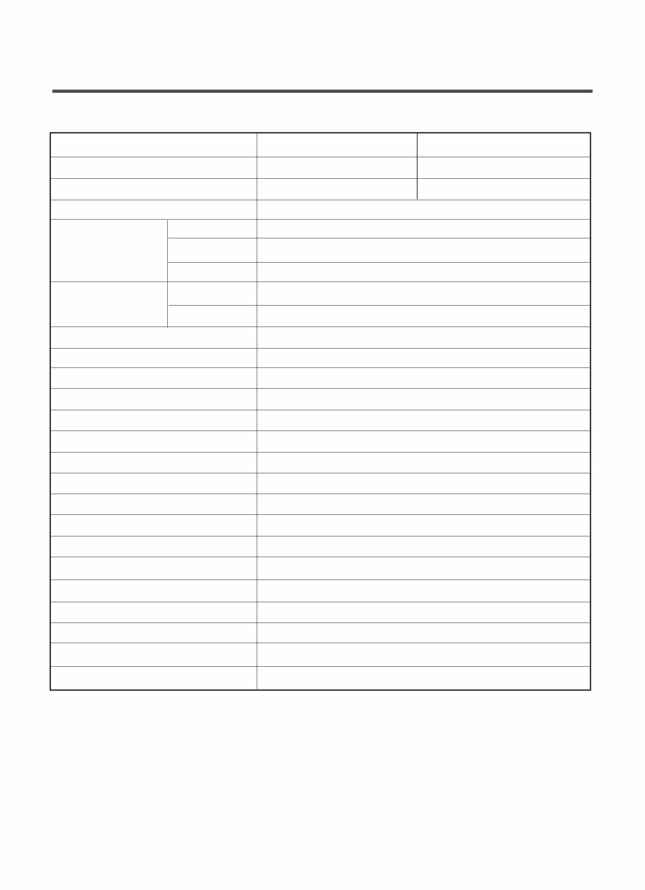
1. SPECIFICATIONS
ITEM WM1812CW/WM1814CW WD-90286BD
COLOR BLUE WHITE TITANIUM
POWER SUPPLY AC 120 V, 60 Hz AC 127V, 60Hz
PRODUCT WEIGHT 173 lbs. (78.5 kg)
WASHING 280 W
DRAIN MOTOR 80 W
WASH HEATER
–
WASH 46 rpm
SPIN
0-900 rpm
CYCLES 5
WASH/RINSE TEMPERATURES 5
SPIN SPEEDS 5
OPTIONS Prewash, Quick Cycle, Extra Rinse, Rinse+Spin, Delay Wash
CUSTOM PROGRAM –
WATER CIRCULATION –
OPERATIONAL WATER PRESSURE 4.5-116 psi (800 kPa)
CONTROL TYPE Electronic
WASH CAPACITY 2.96 cu. ft (3.42 cu. ft. IEC)
DIMENSIONS 27” (W) X 30
1
/
32
” (D) X 38
11
/
16
” (H), 50
13
/
16
” (D, door open)
DELAY WASH up to 9 hours
DOOR SWITCH TYPE PTC + Solenoid
WATER LEVEL 9 steps (by sensor)
LAUNDRY LOAD SENSING Incorporated
ERROR DIAGNOSIS Incorporated
AUTO POWER OFF Incorporated
CHILD LOCK Incorporated
ELECTRIC POWER
CONSUMTION
REVOLUTION SPEED
4
2. FEATURES & TECHNICAL EXPLANATION
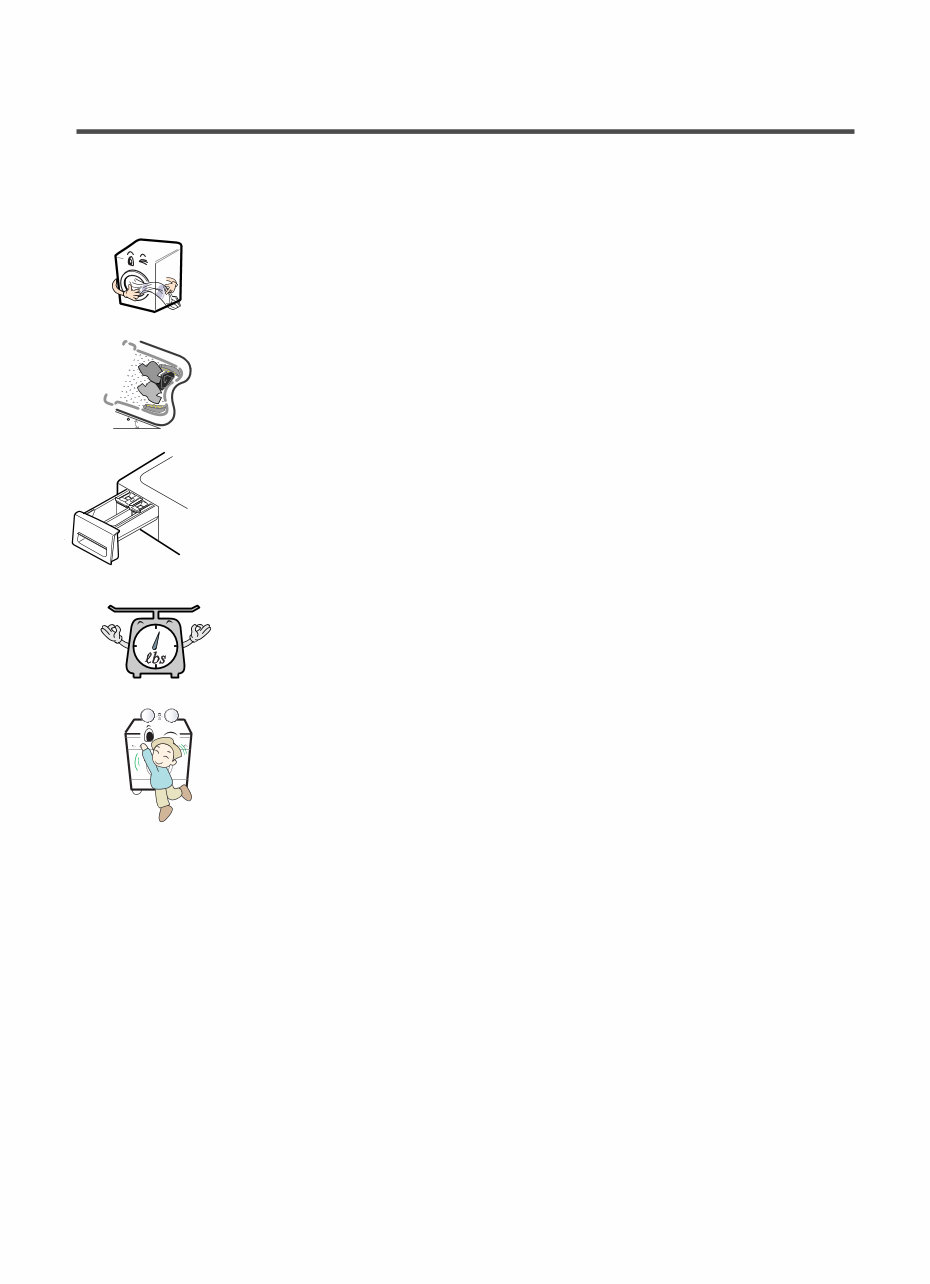
2-1. FEATURES
■
Direct Drive System
The advanced Brushless DC motor directly drives the drum without
belt and pulley.
■
Tilted Drum and Large Door Opening
Tilted drum and large opening make it possible to load
and unload clothing more easily.
■
Time-Released Dispenser
Detergent, fabric softener and bleach are dispensed separately at
the right time during wash cycle.
■
Automatic Wash Load Detection
Automatically detects the load and optimizes the washing time.
■
Child Lock
The Child lock prevents children from pressing any button to
change the settings during operation.
추가선택, 예약,
5
5
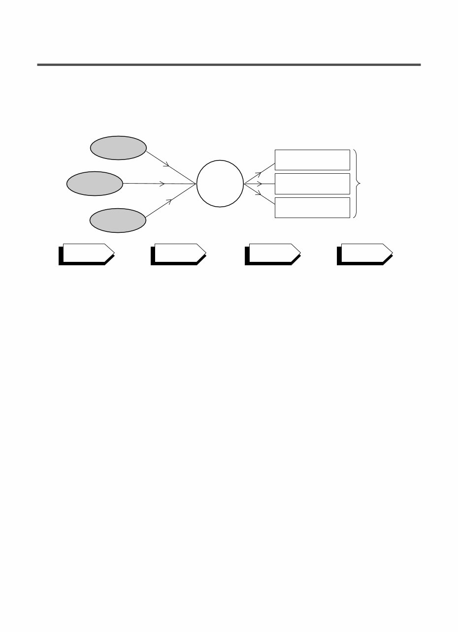
2-2. NEURO FUZZY WASHING TIME OPTIMIZATION
To get the best washing performance, optimal time is determined by the water temperature,
the selected washing temperature, and the size of the load.
2-3. WATER LEVEL CONTROL
● This model incorporates a pressure sensor which can sense the water level in the tub.
● The water supply is stopped when the water level reaches the preset level, the washing
program then proceeds.
● Spinning does not proceed until the water in the tub drains to a certain level.
2-4. DOOR CONTROL
● The door can be opened by pulling the door handle whenever washer is not in operation.
● When the cycle is completed, the DOOR LOCKED light will turn off.
● If a power failure has occurred while in operation, the door will unlock after 5 minutes.
● Clicking sounds can be heard when the door is locked/unlocked.
NEURO-
FUZZY
load
size
selected
washing
temperature
water
temperature
washing time
rinsing time
spin rhythm, time
the best
washing
performance
SENSING PROCESSING DETERMINATION EFFECT

6
2-5. THE DOOR CAN NOT BE OPENED
● While program is operating
● When a power failed and power plug is taken out in operation
● While Door Lock lights turn on.
● White the motor is in the process of intertial rotating, through the operation is paused.
2-6. DOOR LOCKED LAMP LIGHTS
● When the frequency of water level is lower than 22.9 kHz
(It can be canceled when the frequency is more than 23.8 kHz)
● When the temperature inside the tub is higher than 45 °C and water level is not 25.5 kHz
(It can be canceled when the water level is 25.5 kHz or the temperature inside the tub is lower than 40 °C)
2-7. CHILD LOCK
● Use this option to prevent unwanted use of the washer. Press and hold OPTION button for 3 seconds to
lock/unlock control.
● When Child lock is set, “ ” blinks and all buttons are disabled except the Power button. You can lock
the washer while it is operating.
7
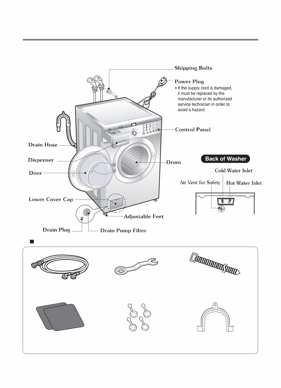
3. PARTS IDENTIFICATION
身
粁? 桁 ? 粁
ACCESSORIES
Wrench
Tie strap (Option)
to secure drain hose to standpipe,
inlet hose, or laundry tub
Hot/Cold (1 each)
Hose
Non-skid pads
Caps(4)
(for covering shipping
bolt holes)
Elbow Bracket
(for securing drain hose)
8
1 Before servicing, ask the customer what the trouble is.
2 Check the setup (power supply is 120 V AC, remove the transit bolts....).
3 Check with the troubleshooting guide.
4 Plan your service method by referring to the disassembly instructions.
5 Service the unit.
6 After servicing, operate the appliance to see whether it functions correctly.
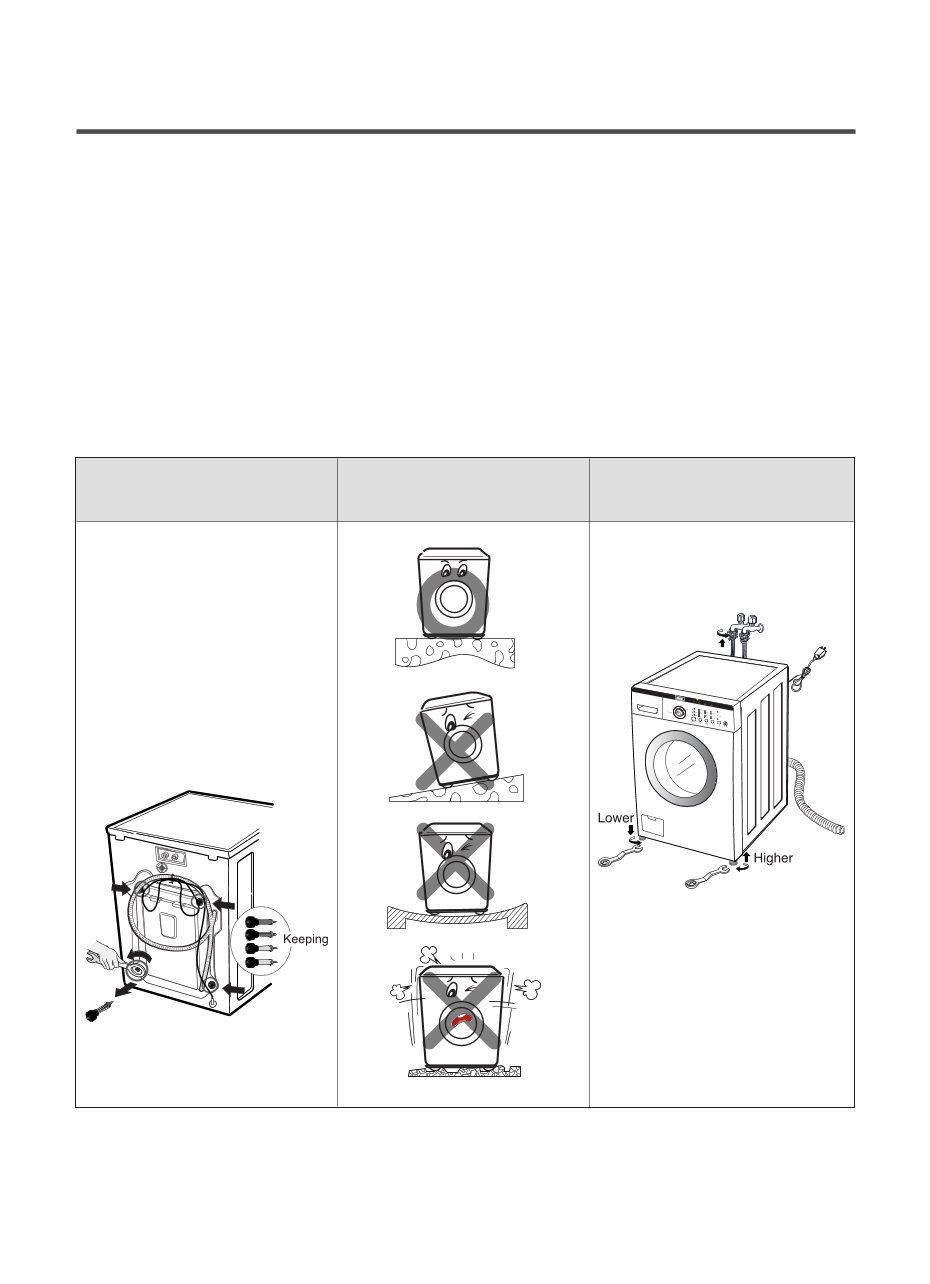
■ STANDARD INSTALLATION
The appliance should be installed as follows:
REMOVE THE SHIPPING INSTALL THE APPLIANCE ADJUST THE
BOLTS ON A FLAT AND FIRM SURFACE LEVELING
Remove the 4 shipping bolts Turn the leveling feet to adjust
with the supplied wrench. the appliance.
※ Do first lower side to remove easily.
Keep the shipping bolts and
spanner for future use.
Insert the 4 caps
(provided) into the hole.
Turn clockwise to raise;
counterclockwise to lower.
4. INSTALLATION & TEST
9
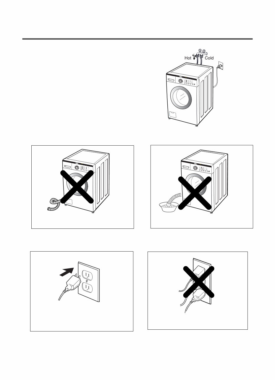
■ HOW TO CONNECT THE INLET HOSE
Verify that the rubber washer is inside of the
valve connector.
Tighten the inlet hose securely to prevent leaks.
■ CONNECT THE DRAIN HOSE
■ CONNECT POWER PLUG
※ The end of the drain hose should be placed less than 96 ” from the floor.
· Connect the power plug to the wall outlet.
· Avoid connecting several electric devices, as
doing so may cause a fire.
· Make sure that the hose is not twisted.
· Avoid submerging the end of the hose.
You're Reading a Preview
What's Included?
Fast Download Speeds
Online & Offline Access
Access PDF Contents & Bookmarks
Full Search Facility
Print one or all pages of your manual
$33.99
Viewed 24 Times Today


Secure transaction
What's Included?
Fast Download Speeds
Online & Offline Access
Access PDF Contents & Bookmarks
Full Search Facility
Print one or all pages of your manual
$33.99
The LG WM2010CW WASHING MACHINE Service Manual is a comprehensive guide that includes the following sections:
- SPECIFICATIONS
- FEATURES AND TECHNICAL EXPLANATION
- PARTS IDENTIFICATION
- INSTALLATION AND TEST
- OPERATION
- WIRING DIAGRAM
- TEST MODE
- TROUBLESHOOTING
- COMPONENT TESTING INFORMATION
- DISASSEMBLY INSTRUCTIONS
- EXPLODED VIEW
This manual is available in English and consists of 37 pages. It is compatible with both Windows and MAC platforms.


