QUICK GUIDE AND APPLIANCES LIST 2/176 599 72 40-80
QUICK GUIDE AND APPLIANCES LIST 3/176 599 72 40-80 Content 1 EWM1000 ............................................................................................................................................ 5 1.1 Access to the diagnostic cycle .................................................................................................... 5 1.2 Rapid reading of alarms .............................................................................................................. 5 1.3 Cancelling the last alarm............................................................................................................. 5 1.4 Phases of the diagnostics test ..................................................................................................... 6 1.5 Reading the alarms..................................................................................................................... 7 1.5.1 Displaying the alarm.............................................................................................................. 7 1.5.2 Examples of alarm display..................................................................................................... 7 1.5.3 Status of alarms during the diagnostics cycle......................................................................... 7 1.6 Table of alarms codes EWM1000 ............................................................................................... 8 1.6.1 Notes concerning certain alarm codes ................................................................................... 9 1.7 Elementary diagram.................................................................................................................. 10 1.7.1 With instantaneous door locking device ............................................................................... 10 1.8 With PTC door locking device ................................................................................................... 11 1.8.1 Key to circuit diagram .......................................................................................................... 12 1.9 Connectors on circuit board EWM1000 ..................................................................................... 13 1.10 Burning on the circuit board EWM1000 ..................................................................................... 14 1.10.1 EWM1000 ........................................................................................................................... 14 1.10.2 Components side (common)................................................................................................ 14 1.10.3 Pushbutton – led side (horizontal buttons) ........................................................................... 15 1.10.4 Pushbutton – led side (vertical buttons) ............................................................................... 15 2 EWM1000plus 2000evo 3000new..................................................................................................... 16 2.1 Control panel ............................................................................................................................ 16 2.2 Sigma/Alpha/Ellipse//Multipanel Built-In/Sigma-ZK/Jewel with or without selector ...................... 17 2.2.1 Access to diagnostics system .............................................................................................. 17 2.2.2 Rapid reading of alarm codes .............................................................................................. 17 2.2.3 Cancelling the last alarm ..................................................................................................... 17 2.3 AEG NexXxt Version with selector and incorporated ON/OFF switch......................................... 18 2.3.1 Access to diagnostics system .............................................................................................. 18 2.3.2 Rapid reading of alarm codes .............................................................................................. 18 2.3.3 Cancelling the last alarm ..................................................................................................... 18 2.4 AEG New Version with right selector and incorporated ON/OFF switch ..................................... 19 2.4.1 Access to diagnostics system .............................................................................................. 19 2.4.2 Rapid reading of alarm codes .............................................................................................. 19 2.4.3 Cancelling the last alarm ..................................................................................................... 19 2.5 DELTA Version without selector and button ON/OFF switch...................................................... 20 2.5.1 Access to diagnostics system .............................................................................................. 20 2.5.2 Rapid reading of alarm codes .............................................................................................. 20 2.5.3 Cancelling the last alarm ..................................................................................................... 20 2.6 CLUB DISPLAY Version with selector and incorporated ON/OFF switch ................................... 21 2.6.1 Access to diagnostics system .............................................................................................. 21 2.6.2 Rapid reading of alarm codes .............................................................................................. 21 2.6.3 Cancelling the last alarm ..................................................................................................... 21 2.7 LCD Version without selector and button ON/OFF switch .......................................................... 22 2.7.1 Access to diagnostics system .............................................................................................. 22 2.7.2 Rapid reading of alarm codes .............................................................................................. 22 2.7.3 Cancelling the last alarm ..................................................................................................... 22 2.8 LCD Version with selector and button ON/OFF switch ............................................................... 23 2.8.1 Access to diagnostics system .............................................................................................. 23 2.8.2 Rapid reading of alarm codes .............................................................................................. 23 2.8.3 Cancelling the last alarm ..................................................................................................... 23 2.9 Phases of the diagnostics test ................................................................................................... 24 2.10 Reading the alarm codes .......................................................................................................... 26 2.10.1 Displaying the alarm............................................................................................................ 26 2.10.2 Examples of alarm displays ................................................................................................. 26 2.11 Table of alarms codes EWM 1000plus EWM2000EVO EWM3000NEW................................. 27 2.12 Basic circuit diagram EWM1000PLUS....................................................................................... 31 2.12.1 Diagram (without aqua control) ............................................................................................ 31 2.12.2 Key to circuit diagram .......................................................................................................... 32 2.12.3 Diagram (with aqua control)................................................................................................. 33 2.12.4 Key to circuit diagram .......................................................................................................... 34 2.13 Basic circuit diagram with sensor EWM2000EVO...................................................................... 35
QUICK GUIDE AND APPLIANCES LIST 4/176 599 72 40-80 2.13.1 Key for circuit diagram......................................................................................................... 36 2.14 Basic circuit diagram with sensor EWM3000NEW ..................................................................... 37 2.14.1 Key for circuit diagram......................................................................................................... 38 2.15 Connectors on circuit board EWM1000plus ............................................................................... 39 2.16 Burning on the circuit board EWM1000plus ............................................................................... 40 3 ENV 06............................................................................................................................................... 41 3.1 Access to the diagnostic cycle .................................................................................................. 41 3.1.1 All version ........................................................................................................................... 41 3.1.2 INPUT version..................................................................................................................... 41 3.1.3 Rapid reading of alarm codes .............................................................................................. 41 3.2 Cancelling the last alarm........................................................................................................... 42 3.3 Phases of the diagnostic cycle .................................................................................................. 43 3.4 Alarm displaying ....................................................................................................................... 44 3.4.1 AEG Version: ...................................................................................................................... 44 3.4.2 Other versions: .................................................................................................................... 44 3.4.3 Examples of alarm display................................................................................................... 44 3.4.4 Operation of alarms during diagnostics ................................................................................ 44 3.5 Table of alarms codes ENV06................................................................................................... 44 3.5.1 Notes concerning certain alarm codes ................................................................................. 44 3.6 Basic circuit diagram EWM1100................................................................................................ 44 3.6.1 Key to circuit diagram EWM1100......................................................................................... 44 3.7 Connectors on circuit board EWM1100 ..................................................................................... 44 3.8 Burning on the circuit board EWM1100 ..................................................................................... 44 3.9 Basic circuit diagram WM EWM2100 ........................................................................................ 44 3.9.1 Key to circuit diagram WM EWM2100.................................................................................. 44 3.10 Basic circuit diagram WM with aqua control EWM2100 ............................................................. 44 3.10.1 Key to circuit diagram WM with Aqua Control EWM2100 ..................................................... 44 3.11 Basic circuit diagram WD EWM2100 ......................................................................................... 44 3.11.1 Key to circuit diagram WD EWM2100 .................................................................................. 44 3.12 Basic circuit diagram WD with aqua control EWM2100.............................................................. 44 3.12.1 Key to circuit diagram WD with aqua control EWM2100....................................................... 44 3.13 Connectors on circuit board WM/WD EWM2100 ....................................................................... 44 3.14 Burning on the circuit board EWM2100 WM/WD ....................................................................... 44 3.15 Basic circuit diagram EWM25xx without aqua control ................................................................ 44 3.15.1 Key to circuit diagram EWM25xx with Aqua Control ............................................................. 44 3.16 Basic circuit diagram EWM25xx without aqua control ................................................................ 44 3.16.1 Key to circuit diagram EWM25xx without Aqua Control ........................................................ 44 3.17 Basic circuit diagram EWM25xx WD without aqua control ......................................................... 44 3.17.1 Key to circuit diagram EWM25xx WD with Aqua Control ...................................................... 44 3.18 Basic circuit diagram EWM25xx WD without aqua control ......................................................... 44 3.18.1 Key to circuit diagram EWM25xx WD without aqua control .................................................. 44 3.19 Basic circuit diagram EWM35xx with aqua control ..................................................................... 44 3.19.1 Key to circuit diagram EWM35xx with Aqua Control ............................................................. 44 3.20 Basic circuit diagram EWM35xx without aqua control ................................................................ 44 3.20.1 Key to circuit diagram EWM35xx without Aqua Control ........................................................ 44 3.21 Connectors on circuit board WM/WD EWM25xx/35xx ............................................................... 44 3.22 Burning on the circuit boards EWM25xx/35xx WM/WD.............................................................. 44 3.23 Burning on the circuit board WD................................................................................................ 44 4 Appliances list .................................................................................................................................... 44
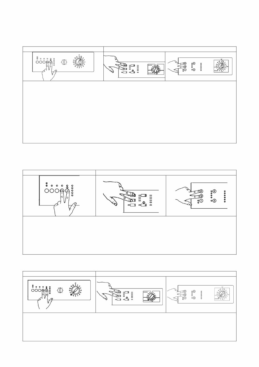
EWM1000 1 EWM1000 1.1 Access to the diagnostic cycle version with horizontal pushbuttons version with vertical pushbuttons 1. Switch off the appliance. 2. Press and hold down the START/PAUSE button and any one of the OPTION buttons simultaneously. horizontal version, while for vertical version pushbuttons are 2 and 3. 3. Holding down both buttons, switch the appliance on by turning the programme selector one position clockwise. 4. Continue to hold down the START/PAUSE button and the OPTION button horizontal version, while for vertical version pushbuttons are 2 and 3, until the LEDs begin to flash (at least 2 seconds). 5. To exit the diagnostics system switch the appliance off, on and then off again. IMPORTANT: The position of the START/PAUSE button varies according to the model, and is therefore not always the same. 1.2 Rapid reading of alarms The last alarm can be displayed even if the programme selector is not in the tenth position (diagnostics) or if the appliance is in normal operating mode (e.g. while the washing programme is in operation): version with horizontal pushbuttons version with vertical pushbuttons 1. Press START/PAUSE and any one of the option buttons simultaneously for horizontal version, while for vertical version pushbuttons are 2 and 3, for at least two seconds: the LEDs first switch off, and then display the flashing sequence corresponding to the alarm condition. 2. The alarm sequence continues as long as the two buttons are held down. 3. While the alarms are displayed, the current cycle being performed continues or, if the appliance is in the programme selection phase, the options previously selected remain in memory. 1.3 Cancelling the last alarm version with horizontal pushbuttons version with vertical pushbuttons 1. Access alarm reading mode (tenth selector position) 2. Press and hold down START/PAUSE and any one of the option keys simultaneously for horizontal version, while for vertical version pushbuttons are 2 and 3. 3. Hold the START/PAUSE and OPTION button down until the LEDs begin to flash (about 5 seconds)
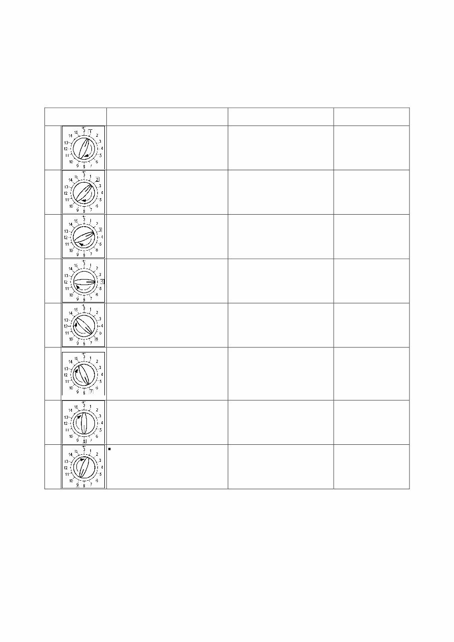
EWM1000 QUICK GUIDE AND APPLIANCES LIST 6/176 599 72 40-80 1.4 Phases of the diagnostics test After accessing the diagnostics cycle, and irrespective of the type of control board fitted to the appliance (i.e. vertical or horizontal buttons) and the configuration of the selector, turn the programme selector clockwise to perform the diagnostics cycle for the various components and to read the alarms. All the alarms are enabled during the diagnostics cycle. Position of selector Components activated Conditions of operation Function tested 1 - All the LEDs light in sequence - When a button is pressed, the corresponding LED lights (and the buzzer may sound) Always enabled Operation of the user interface 2 - Door safety interlock - Washing solenoid valve Door locked Water level lower than anti- overflow level Maximum time 5 minutes Water ducted through washing compartment 3 - Door safety interlock - Pre-wash solenoid valve Door locked Water level lower than anti- overflow level Maximum time 5 minutes Water ducted through pre-wash (bleach) compartment 4 - Door safety interlock - Washing and pre-wash solenoid valves Door locked Water level lower than anti- overflow level Maximum time 5 minutes Water ducted through conditioner compartment 6 - Door safety interlock - Wash solenoid (if the water in the tub is below 1st level) - Heating element Door locked Water level > 1st level Maximum time 10 minutes or up to 90°C (*) Heating 7 - Door safety interlock - Wash solenoid (if the water in the tub is below 1st level) - Motor (55 rpm clockwise, 55 rpm anti-clockwise, impulse at 250 rpm) Door locked Water level > 1st level Check for leaks from the tub 8 - Door safety interlock - Drain pump - Motor up to 650 rpm then at maximum spin speed Door locked Water level lower then anti- boiling level for spinning Drain and spin, check for congruence in closure of pressure switch levels 9 Only for top-loaders with drum positioning system: - Door safety interlock - Motor (25 rpm) - Drain pump Door locked Water level lower then anti- boiling level Maximum time 2 minutes Test for positioning of drum (*) In most cases, this time is sufficient to check the heating function. However, the time can be increased by repeating the heating phase without draining the water: pass for a moment to a different phase of the diagnostics cycle and then back to the heating check phase (if the temperature is higher than 80°C, heating does not take place).
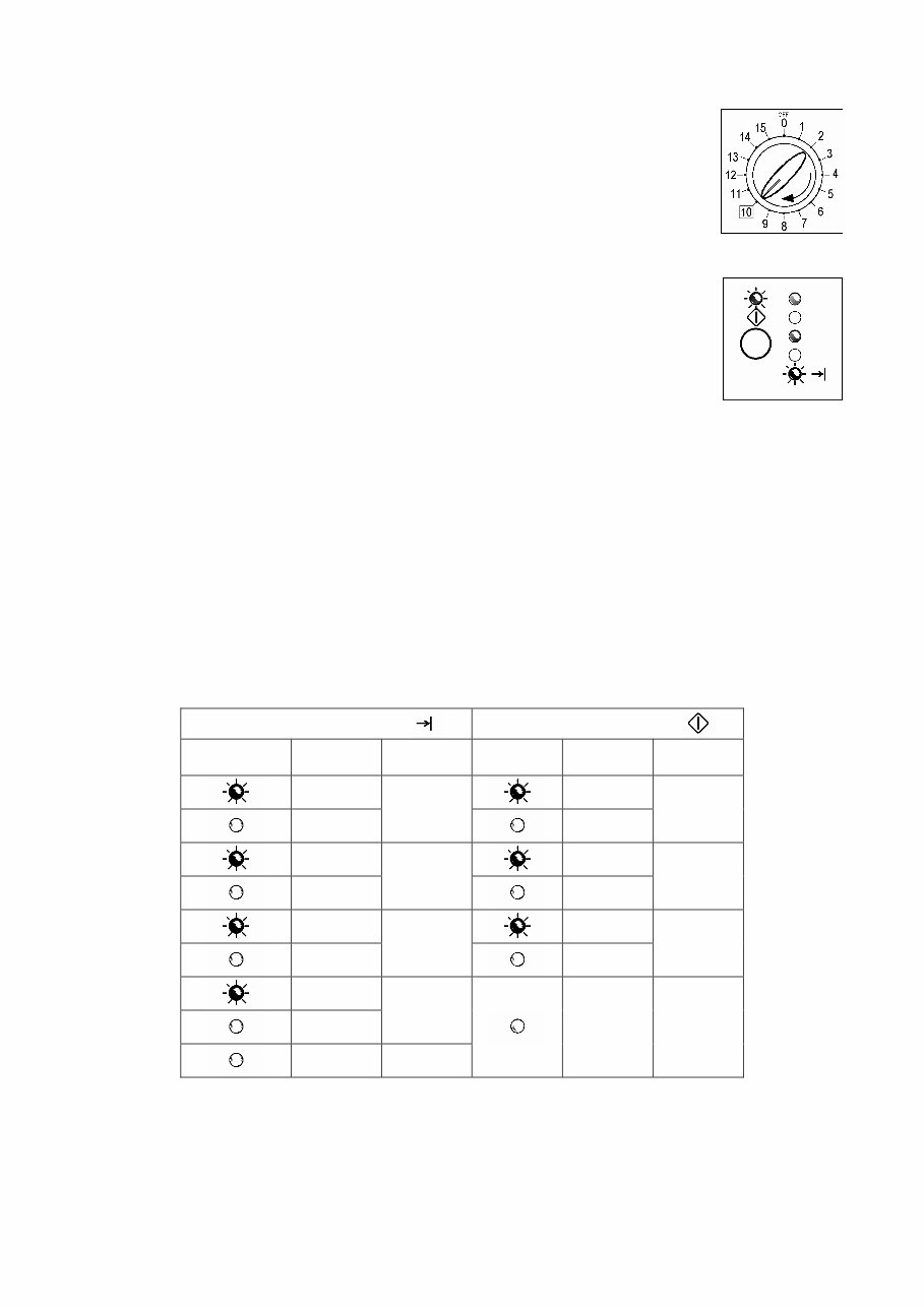
EWM1000 QUICK GUIDE AND APPLIANCES LIST 7/176 599 72 40-80 1.5 Reading the alarms Proceed as follows to read the last alarm condition stored in the EEPROM on the control board: • Access diagnostics mode. • Irrespective of the type of control board and configuration, turn the programme selector clockwise to the tenth position. 1.5.1 Displaying the alarm The alarm is displayed by a repeated flashing sequence of the two LEDs (0.4 seconds ON, 0.4 seconds OFF, with a pause of 2.5 seconds between each sequence). The buzzer (if featured) sounds a series of “beeps” in synchronization with the flashing of the LEDs. • END OF CYCLE indicator → indicates the first digit of the alarm code (family) • START/PAUSE → indicates the second digit of the alarm code (number within the family). These two LEDs are present on all models (though configured in different positions) and flash simultaneously. Notes: • The first letter of the alarm code “E” (Error) is not displayed since it is the same for all alarm codes. • The alarm code families are expressed in hexadecimal form. In other words: → A is represented by 10 flashes → B is represented by 11 flashes → ... → F is represented by 15 flashes • Configuration errors are displayed by the flashing of all the LEDs (user interface not configured). 1.5.2 Examples of alarm display Example: Alarm E43 (problems with the door safety interlock triac) will be displayed as follows: • four flashes of the END OF CYCLE LED indicate the first digit E43; • three flashes of the START/PAUSE LED indicate the second digit E43; END OF CYCLE LED START/PAUSE LED ON/OFF Time (seconds) Value ON/OFF Time (seconds) Value 0.4 0.4 0.4 1 0.4 1 0.4 0.4 0.4 2 0.4 2 0.4 0.4 0.4 3 0.4 3 0.4 0.4 4 2.5 Pause 3,3 Pause 1.5.3 Status of alarms during the diagnostics cycle All the alarms are enabled during the components diagnostics test.
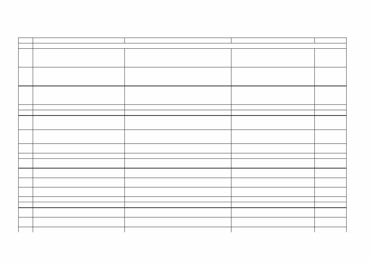
EWM1000 QUICK GUIDE AND APPLIANCES LIST 8/176 599 72 40-80 1.6 Table of alarms codes EWM1000 Alarm Description Possible fault Action/Machine status Reset E00 No alarm E11 Difficulty in filling during wash phase Tap closed or water pressure insufficient; Drain hose incorrectly positioned; Water fill solenoid faulty; Leaks from pressure switch hydraulic circuit; Pressure switch faulty; Wiring faulty; Circuit board faulty. Cycle paused, door closed Start E13 Water leakage Drain hose incorrectly positioned; Water pressure insufficient; Water fill solenoid faulty; Leaks or blockage in pressure switch hydraulic circuit; Pressure switch faulty; Circuit board faulty. Cycle paused, door closed Start E21 Difficulties in draining Drain hose kinked/blocked/incorrectly positioned; Drain filter clogged or dirty; Drain pump faulty; Pressure switch faulty; Wiring faulty; Circuit board faulty; Current leakage from heating element to ground. Cycle paused Start E23 Drain pump triac faulty Drain pump faulty; Wiring faulty; Circuit board faulty. Safety drain - Cycle stopped, door open Selector on “0” E24 Problems with «sensing» of drain pump triac Circuit board faulty. Safety drain – Cycle stopped, door released Selector on “0” E33 Incongruence between contact closure of anti- boiling and 1st level of pressure switch Pressure switch faulty; Current leakage from heating element to ground; Heating element; Wiring faulty; Circuit board faulty. Safety drain - Cycle stopped, door open Selector on “0” E35 Water overflow Water fill solenoid faulty; Leaks from pressure switch hydraulic circuit; Pressure switch faulty; Wiring faulty; Circuit board faulty. Cycle blocked, door closed. Safety drain. Drain pump (sequence 5 min. ON - 5 min. OFF) Selector on “0” E36 «sensing» circuit of anti-boiling pressure switch faulty Circuit board faulty. Cycle blocked, door closed Selector on “0” E37 «sensing» circuit of 1st level faulty Circuit board faulty. Cycle blocked, door closed Selector on “0” E39 HV «sensing» circuit of anti-flooding pressure switch faulty Circuit board faulty. Cycle blocked, door closed Selector on “0” E41 Door open Door safety interlock faulty; Wiring faulty; Circuit board faulty. Cycle paused Start E42 Problems with aperture of door Door safety interlock faulty; Wiring faulty; Circuit board faulty Cycle paused Start or Selector on “0” E43 Power triac on door interlock faulty Door safety interlock faulty; Wiring faulty; Circuit board faulty. Safety drain, door released Selector on “0” E44 Door interlock «sensing» faulty Circuit board faulty. Safety drain, door released Selector on “0” E45 «sensing» on door interlock triac faulty Circuit board faulty. Safety drain, door released Selector on “0” E51 Motor power triac short-circuited Circuit board faulty; Current leakage from motor or wiring. Cycle blocked, door closed (after 5 attempts in diagnostics or immediate during selection) Selector on “0” E52 No signal from motor tachimetric generator Motor faulty; Wiring faulty; Circuit board faulty. Cycle blocked, door closed (after 5 attempts in diagnostics or immediate during selection) Selector on “0” E53 «sensing» circuit on motor triac faulty Circuit board faulty. Cycle blocked Selector on “0”
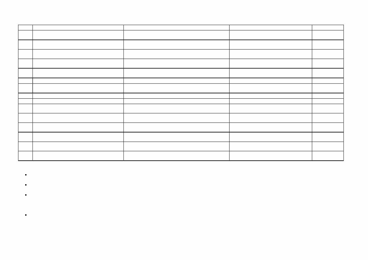
EWM1000 QUICK GUIDE AND APPLIANCES LIST 9/176 599 72 40-80 Alarm Description Possible fault Action/Machine status Reset E54 Motor relay contacts sticking Circuit board faulty; Current leakage from motor or wiring. Cycle blocked, door closed (after 5 attempts in diagnostics or immediate during selection) Selector on “0” E61 Insufficient heating during washing NTC sensor faulty; Heating element faulty; Wiring faulty; Circuit board faulty. Heating phase skipped --- E62 Overheating during washing NTC sensor faulty; Heating element faulty; Wiring faulty; Circuit board faulty. Safety drain (with cooling water fill) - Stop with door open Selector on “0” E66 Power relay for heating element faulty Circuit board faulty; Current leakage from heating element or wiring to ground. Safety drain (with cooling water fill) - Stop with door open Selector on “0” E71 NTC washing sensor faulty NTC sensor faulty; Wiring faulty; Circuit board faulty. Heating phase skipped --- E82 Error in reset position of selector Circuit board faulty. Cycle cancelled Selector on “0” E83 Error in reading selector position Configuration data incorrect; Circuit board faulty. During the cycle continues normally, switches off completely during selection --- E93 Incorrect machine configuration Configuration data incorrect; Circuit board faulty. Appliance blocked Selector on “0” E94 Incorrect washing cycle configuration Configuration data incorrect; Circuit board faulty. Appliance blocked Selector on “0” E95 Communications error between microprocessor and EEPROM Circuit board faulty. Appliance blocked Selector on “0” E96 Incongruence between hardware version and configuration. Configuration data incorrect; Circuit board faulty. Appliance blocked Selector on “0” E97 Incongruence between programme selector and cycle configuration Configuration data incorrect; Circuit board faulty. Appliance blocked Selector on “0” EB1 Power supply frequency of appliance incorrect Mains power supply problems (incorrect / interference); Circuit board faulty. Cycle blocked until normal power supply conditions are restored Selector on “0” EB2 Voltage too high Mains power supply problems (incorrect / interference); Circuit board faulty. Cycle blocked until normal power supply conditions are restored Selector on “0” EB3 Voltage too low Mains power supply problems (incorrect / interference); Circuit board faulty. Cycle blocked until normal power supply conditions are restored Selector on “0” 1.6.1 Notes concerning certain alarm codes Configuration alarms E93-E96: If these alarms are generated (when the appliance is switched on), operation of the appliance is blocked and all the LEDs light. The diagnostics procedure cannot be accessed; the only option is to switch the appliance OFF (by turning the selector to position “0”). Configuration alarm E94: For this alarm code, only the family for alarm “9” is displayed; the diagnostics procedure cannot be accessed, and the “rapid alarm display” function cannot be used. Alarms EB1-EB2-EB3: In the event of problems with the mains power supply, the appliance remains in alarm mode until the mains frequency or voltage are restored to the correct value or the appliance is switched off (by turning the programme selector to “0”). The family of alarm “B” is displayed; the diagnostics procedure cannot be accessed, and the “rapid alarm display” function cannot be used. The complete alarm code can be read only when the abnormal situation has ceased. Alarms E51- E52: During the diagnostics test, all the alarms are displayed. Normally, when the programme selector is turned from one test phase to another, the appliance exits the alarm condition and performs the phase selected. This does not take place in the case of alarms E51 (power triac on motor short-circuited) and E52 (no signal from the tachymetric generator on the motor): in these cases, the only option to exit the alarm condition is to switch the appliance OFF by turning the selector to position “0” (reset).
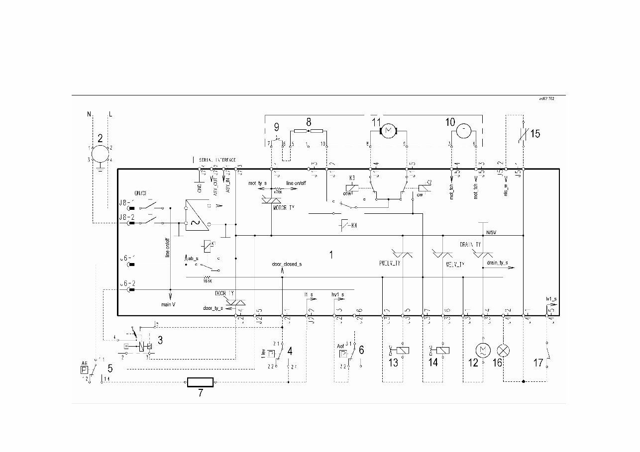
EWM1000 QUICK GUIDE AND APPLIANCES LIST 10/176 599 72 40-80 1.7 Elementary diagram 1.7.1 With instantaneous door locking device
This service manual for Electrolux washing machines equipped with the EWM 1000 Plus electronic control system provides detailed technical guidance for service engineers experienced in traditional washing machine repair. It offers essential information on appliances featuring the EWM 1000 Plus system, including a main electronic board and a control/display board in the "AEG Nexxxt" version.
The manual covers the general characteristics of the system, control panel operation, washing programs, and technical specifications. Additionally, it includes a comprehensive guide to diagnostics, enabling precise fault detection and repair. Whether addressing control panel issues or performing routine servicing, this manual ensures accurate, model-specific support.
Available in digital format, this manual can be accessed on computers and mobile devices, making it ideal for both workshop environments and on-site repairs. It’s an indispensable resource for engineers maintaining Electrolux washing machines with EWM 1000 Plus control systems.
Printable: Yes Language: English Compatibility: Pretty much any electronic device, incl. PC & Mac computers, Android and Apple smartphones & tablet, etc. Requirements: Adobe Reader (free)