


STIH)
STIHL RE 521, 551, 581, 661, 961 2005-02

1 RE 521, RE 551, RE 551 PLUS, RE 581, RE 581 PLUS, RE 661, RE 661 PLUS, RE 961, RE 961 PLUS
q
© ANDREAS STIHL AG & Co. KG, 2007
Contents
1. Introduction 3
2. Safety regulations 3
3. Technical
Specifications 4
3.1 Motor 4
3.2 Pump 4
3.3 Burner 4
3.4 Weights and
dimensions 4
3.5 Capacities 5
3.6 Sound pressure level 5
3.7 Settings for the
automatic scale
inhibitor system 5
3.8 Settings for CO2 content,
O2 content and soot 5
3.9 Tightening torques 6
4. Functional description,
function diagram 8
4.1 Water conducting
system 8
4.1.1 High-pressure pump 8
4.1.2 Automatic scale
inhibitor system 9
4.1.3 Regulation valve block 9
4.1.4 Adding detergent,
automatic clear rinse 10
4.2 Heating system 10
4.2.1 Heat exchanger 11
4.2.2 Level monitoring
in the fuel tank 11
4.3 Safety system 11
4.3.1 Safety valve 12
4.3.2 Flow monitor 12
4.3.3 Temperature control 12
4.3.4 Thermal release 13
4.3.5 Monitoring the flame 13
4.4 Function diagram 13
5. Summary of
possible faults 15
5.1 Control panel,
significance of the
various indicators 15
5.2 Diagnostic codes
RE 661, RE 961 17
5.3 Flow diagram of high-
pressure pump 19
5.4 Summary of
electric motor faults 23
5.5 Summary of heating
system faults 25
6. Cover, chassis 27
6.1 Open shroud and
right covers, close
RE 521, RE 551,
RE 581 27
6.2 Open shroud and
cover, close
RE 661, RE 961 27
6.3 Shove the motor/pump
unit into service
position 28
6.4 Exchanging castors 29
6.5 Changing a wheel 29
6.6 Hose reel
(PLUS models) 30
6.6.1 Removing / mounting
the hose reel 30
6.6.2 Seal high-pressure
connection
RE 551 PLUS,
RE 581 PLUS 31
6.6.3 Removing / installing
hose reel RE 551 PLUS,
RE 581 PLUS 33
6.6.4 Removing / installing
hose and cable drum
RE 661 PLUS,
RE 961 PLUS 33
6.6.5 Seal high-pressure
connection
RE 661 PLUS,
RE 961 PLUS 35
6.7 High-pressure
connection of models
without hose reel 36
7. Regulation valve
block 37
7.1 Safety valve 37
7.2 Non-return valve 38
7.3 Flow monitor 39
7.4 Start-Stop switch 40
7.4.1 Removing/installing 40
7.4.2 Setting the Start-Stop
switch 40
7.5 Reed switch 41
7.5.1 Removing/installing 41
7.5.2 Setting 42
7.6 Hydraulic accumulator
RE 661, RE 961 43
7.7 Bypass valve and
control piston 43
7.8 Removing / installing the
regulation valve block 46
7.9 Adjusting pressure
control 46
8. High-pressure pump 48
8.1 Screen in intake port 48
8.2 Removing / installing
intake port 48
8.3 Removing / fitting
the injector 49
8.4 Removing / installing
intake / delivery valves 50
8.5 Valve block and high
pressure cups
Removing / installing 51
8.6 Removing / installing
ceramic pistons 53
8.7 Oil expansion tank and
float-operated switch
Removing / installing 54
8.8 Removing / installing
pump housing 55
8.9 Open pump housing 56
8.10 Disassemble pump
housing RE 521,
RE 551, RE 581 56
8.11 Disassemble pump
housing
RE 661, RE 961 59
8.12 Disassembly /
assembly of
connecting rods 62
8.13 Exchange piston
oil seals 63
8.14 Exchange camshaft
sealing ring
RE 661, RE 961 64
9. Remove / install
electric motor 64
10. Adding detergent,
automatic clear rinse 68
11. Automatic scale
inhibitor system 69
11.1 Adjust hardness 69
11.2 Removing and installing
the scale inhibitor
metering valve 69

2 RE 521, RE 551, RE 551 PLUS, RE 581, RE 581 PLUS, RE 661, RE 661 PLUS, RE 961, RE 961 PLUS
Contents
11.3 Scale inhibitor
concentrate level
monitor 70
12. Heating system 71
12.1 Set burner 71
12.2 Solenoid 73
12.3 Fan housing 74
12.3.1 Removing / installing 74
12.3.2 Disassembly /
assembly 74
12.4 Burner motor 76
12.5 Burner insert 76
12.5.1 Removing/installing 76
12.5.2 Nozzle assembly and
ignition electrodes,
Removing / installing 77
12.6 Heat exchanger 78
12.6.1 Removing / installing
heating coil 78
12.6.2 Removing / installing
burner casing 80
12.7 Removing / installing
insulation 81
12.8 Temperature sensor 81
12.9 Thermal release 81
12.10 Monitoring the flame 82
12.11 Level display and float-
operated switch
in the fuel tank 83
13. Electrical system 85
13.1 ESD precautions 85
13.2 Connecting /
disconnecting
electrical components 85
13.3 RE 521, RE 551,
RE 581 86
13.3.1 Opening / closing
switch box cover 86
13.3.2 Printed circuit board
with main switch 86
13.3.3 Turn motor idle
off / on 87
13.3.4 Setting
maintenance interval 88
13.3.5 Pressure gauge 89
13.3.6 Detergent
metering valve 89
13.3.7 Contactor 90
13.3.8 Fuses 90
13.3.9 Transformer 90
13.3.10 Removing / installing
switch box housing 91
13.3.11 Power cables 91
13.3.12 Capacitors
RE 521, RE 551 92
13.4 RE 661, RE 961 93
13.4.1 Opening / closing
switch box cover 93
13.4.2 Display
operating hours 93
13.4.3 Setting
temperature display 94
13.4.4 Turn motor idle off/on 94
13.4.5 Setting maintenance
interval 94
13.4.6 Circuit board
function test 95
13.4.7 Main switch 96
13.4.8 Display unit with
temperature control 97
13.4.9 Pressure gauge 98
13.4.10 Detergent
metering valve 99
13.4.11 Circuit board 100
13.4.12 Contactor 100
13.4.13 Fuses 101
13.4.14 Relay 101
13.4.15 Transformer 102
13.4.16 Terminal blocks 103
13.4.17 Power cables 103
13.4.18 Removing / installing
switch box 104
13.5 Disconnect
the electric motor 104
13.6 Removing / installing
ignition transformer 105
14. Spray attachment 106
14.1 VarioPress gun 106
14.2 Spray lance,
spray head 108
14.3 Remove/install 110
15. Maintenance 111
15.1 Maintenance
schedule 111
15.2 Reading out
operating hours 112
15.3 Check oil level,
change oil 112
15.4 Clean screen
in water feed 113
15.5 Replace fuel filter 114
15.6 Replace fuel nozzle 114
15.7 Check fuel for water 114
15.8 Cleaning fuel tank
RE 661, RE 961 115
15.9 Cleaning fuel tank
RE 521, RE 551,
RE 581 115
15.10 Descaling 116
15.11 Cleaning heating coil 117
15.12 Setting the burner 118
15.13 Setting the fuel pump 118
15.14 Set soot level,
CO
2
content 119
15.15 Calculate exhaust
loss 122
16. Special tools
and service tools 124
16.1 Special
Servicing Tools 124
16.2 Service accessories 125
17. Circuit diagrams 126
17.1 Legends to circuit
diagrams: RE 521,
RE 551, RE 581 126
17.2 Circuit diagram for
RE 521,
Legend (b 17.1) 127
17.3 Circuit diagram for
RE 551
Legend (b 17.1) 128
17.4 Circuit diagram for
RE 581
Legend (b 17.1) 129
17.5 Legend to circuit
diagram for RE 661,
RE 961 130
17.6 Circuit diagram
for RE 661, RE 961
Legend (b 17.5) 131

3 RE 521, RE 551, RE 551 PLUS, RE 581, RE 581 PLUS, RE 661, RE 661 PLUS, RE 961, RE 961 PLUS
These repair instructions include a
detailed description of the essential
repair tasks for the following series:
STIHL RE 521, RE 551, RE 581,
RE 661 and RE 961.
The descriptions also apply for the
PLUS models. Exceptions are cited
in the text.
A test bed with the necessary water
and power supplies should be
provided for the repair work. The
unit must be connected to the
pressurized water supply and the
fault described by the customer
reproduced, with the customer
demonstrating the fault if necessary.
The customer’s attention must be
drawn to the User Manual if the
machine is operated incorrectly.
A fault on the machine may be due
to several causes. For
troubleshooting, refer to the
"Summary of possible faults" (b 5)
and the STIHL Service Training
System "High-pressure cleaners".
The illustrated spare parts lists must
also be used for all repair work.
These lists show the installation
position and order in which the
individual assemblies should be
assembled.
Note the "Technical Information"
bulletins! They contain information
on technical changes implemented
after publication of this Repair
Manual.
The Technical Information bulletins
also supplement the spare parts list
until a new edition is printed!
Repair Manuals and Technical
Information bulletins should always
be kept on hand wherever repairs
are carried out.
They must not be passed on to third
parties.
Only original STIHL spare parts
may be used!
To help you use this manual and
understand it more clearly, the text
and illustrations are marked by
graphic symbols as follows:
In the text:
: = Instruction describing the
action illustrated in the figure
immediately above the text box
– = Instruction describing an action
that is not illustrated in the figure
above the text
b 5.3 = Reference to another
chapter, in this case chapter 5.3
In the illustrations:
A Item pointer (short)
a Direction of movement
(long arrow)
High-pressure cleaners may only be
repaired by qualified electricians (in
accordance with BGV A2 and
DIN VDE 0701 / 0702 in Germany)
with due regard for national safety
regulations and the provisions of the
User Manual.
As a rule, pull the power plug when
performing all repairs. In individual
cases, the device needs to be
operating when the switch box is
open. In this case, avoid all contact
with voltage-conducting parts, and
take extra care.
1. Introduction 2. Safety regulations

4 RE 521, RE 551, RE 551 PLUS, RE 581, RE 581 PLUS, RE 661, RE 661 PLUS, RE 961, RE 961 PLUS
3. Technical Specifications
1)
PLUS models
2)
circuit breaker type C
required in accordance with
EN 60 898-1
3)
only for Norway
RE 521 RE 551
PLUS
RE 551
PLUS
(only GB, IRL)
RE 581,
RE 581
PLUS
RE 661,
RE 661
PLUS
RE 961
PLUS
3.1 Motor
Voltage: 230 V 230 V 230 V 400 V
(3 x 230 V)
3)
400 V 400 V
Frequency: 50 Hz 50 Hz 50 Hz 50 Hz 50 Hz 50 Hz
Power output: 3.1 kW 3.4 kW 3.0 kW 4.5 kW 5.6 kW 7.9 kW
Fuse: 16 A
2)
16 A
2)
13 A
2)
3 x 16 A
2)
3 x 16 A
2)
3 x 16 A
2)
Type of protection: IP X5 IP X5 IP X5 IP X5 IP X5 IP X5
Protection class: I I I I I I
3.2 Pump
Working pressure: 20 to 105
bar
20 to 135
bar
20 to 105
bar
20 to 160
bar
20 to 170
bar
20 to 200
bar
Max. permissible pressure: 200 bar 200 bar 200 bar 200 bar 250 bar 250 bar
Max. kickback force 21 N 26 N 22 N 32 N 42 N 55 N
Water throughput
to EN 60335-2-79: 520 l/h 570 l/h 580 l/h 650 l/h 800 l/h 1,000 l/h
Max. water feed pressure: 10 bar 10 bar 10 bar 10 bar 10 bar 10 bar
Max. water feed
temperature:
40 °C 40 °C 40 °C 40 °C 40 °C 40 °C
High-pressure hose
(Plus models)
10 m 15 m 15 m 10 / 15 m
1)
10 / 20 m
1)
20 m
3.3 Burner
Fuel tank capacity 15 l 15 l 15 l 15 l 35 l 35 l
Fuel pressure: 12 bar 12 bar 12 bar 12 bar 10 bar 10 bar
Heat output: 49 kW 49 kW 49 kW 62 kW 80 kW 80 kW
3.4 Weights and
dimensions
Length approx. (normal /
PLUS models):
1,050 mm 1,050 mm 1,050 mm 1,050 mm 1150 1150
Width approx.: 680 mm 680 mm 680 mm 680 mm 700 700
Height approx.: 760 mm 770 mm 770 mm 760 mm /
770 mm
1)
1,010 mm 1,010 mm
Weight: 125 kg 133 kg 133 kg 131 kg /
134 kg
1)
180 kg /
185 kg
1)
189 kg

5 RE 521, RE 551, RE 551 PLUS, RE 581, RE 581 PLUS, RE 661, RE 661 PLUS, RE 961, RE 961 PLUS
3.7 Settings for the automatic
scale inhibitor system
3.8 Settings for CO
2
content,
O
2
content and soot
RE 521 RE 551
PLUS
RE 551
PLUS
(only GB, IRL)
RE 581,
RE 581
PLUS
RE 661,
RE 661
PLUS
RE 961
PLUS
3.5 Capacities
Oil capacity: 450 ml 1,000 ml 1,000 ml 1,000 ml 1,000 ml 1,000 ml
Oil for high-pressure
pump:
SAE
15 W 40
SAE
15 W 40
SAE
15 W 40
SAE
15 W 40
SAE
15 W 40
SAE
15 W 40
Detergent tank A /
B (RE 661, RE 961)
10 l 10 l 10 l 10 l 15 l /
10 l
15 l /
10 l
3.6 Sound pressure
level
Weighted sound pressure
level at a distance of 1 m:
to ISO 45635: 72.5 dB(A) 73.1 dB(A) 73.1 dB(A) 74.1 dB(A) 73.8 dB(A) 74.1 dB(A)
Setting Descrip-
tion
°dH mg/l Grains °e °f ppm Ca
0 very soft 0 -7 0 - 17 0 - 1 0 - 8.8 0 - 12.5 0 - 50
1 soft approx. 7 17 - 60 1.1 - 3.5 approx. 8.8 approx. 12.5 approx. 50
2 medium 7 - 14 60 - 128 3.6 - 7.5 8.8 - 17.5 12.5 - 25. 1 51 - 150
3 hard 14 - 21 128 - 180 7.6 - 10.5 17.5 - 26.3 25.1 - 37.6 151 - 300
4 very hard > 21) > 180 > 10.5 > 26.3 > 37.6 > 300
RE 521 RE 551
PLUS
RE 551
PLUS
(only GB,
IRL)
RE 581,
RE 581
PLUS
RE 661,
RE 661
PLUS
RE 961
PLUS
Target value
CO
2
(%) / tolerance 10 / +0.5 10 / +0.5 10 / +0.5 10.5 / +0.5 10.5 / +0.5 10.5 / +0.5
O
2
(%) / tolerance 7.4 / -0.6 7.4 / -0.6 7.4 / -0.6 6.8 / -0.8 6.7 / -0.7 6.7 / -0.7
Soot 0 0 0 0 0 0

6 RE 521, RE 551, RE 551 PLUS, RE 581, RE 581 PLUS, RE 661, RE 661 PLUS, RE 961, RE 961 PLUS
1)
Thread must be clean and dry
3.9 Tightening torques
Component Connecting element Thread size Tightening
torque (Nm)
Remarks
Caster fastening screws Hex bolt M8x16 15
1
)
Safety valve in regulation valve block --- 25
1
)
Piston guide in the regulation valve block Threaded bush --- 25
1
)
High-pressure hose to piston guide --- 40
1
)
High-pressure hose to regulation valve
block
Banjo bolt G3/8“x41 20
1
)
Lock nut of headless pin
(set working pressure)
Hex nut M6 7
1
)
Lock nut, selector sleeve
(set working pressure)
Hex nut M24x1.5 20 size 27
1
)
Banjo bolt of the control piston in the valve
block
Banjo bolt --- 25 size 27
1
)
Regulation valve block to high-pressure
pump
Banjo bolt --- 30
1
)
Screw plug in the regulation valve block Banjo bolt M24x1.5 25
1)
Intake port to valve block Banjo bolt --- 20 size 30
1
)
Injector to valve block Banjo bolt --- 10
1)
Intake and delivery valves to valve block Screw plug --- 55 size 24
1
)
Valve block to pump housing Socket-head screw M8x70 20
1)
Piston to piston guide RE 521, RE 551,
RE 581
Hex nut --- 15
1
)

7 RE 521, RE 551, RE 551 PLUS, RE 581, RE 581 PLUS, RE 661, RE 661 PLUS, RE 961, RE 961 PLUS
1
) Thread must be clean and dry
Component Connecting element Thread size Tightening
torque (Nm)
Remarks
Piston to piston guide RE 661, RE 961 Hex nut --- 13
1
)
Screw plug in valve block --- 8
1)
Cover to pump housing RE 521, RE 551,
RE 581
Socket-head screw M6x16 10
1
)
Cover to pump housing RE 661, RE 961 Socket-head screw M6x16 15
1
)
Bearing cover to stator housing Hex bolt M6x25 10
1
)
Bearing cover to pump casing Socket-head screw M6x20 10
1
)
Fuel pump to drive shaft Socket-head screw M5x16 7
1
)
Fan wheel to drive shaft Headless pin 20
1
)
High pressure hose to distributor Banjo bolt G3/8“x41 20
1
)
Front cover to heating coil Hex nut M18x1.5 20 size 27
1
)
Oil drain plug Screw plug --- 20
1
)
Fuel nozzle to nozzle assembly Hexagon socket
wrench
--- 16
1
)
8 RE 521, RE 551, RE 551 PLUS, RE 581, RE 581 PLUS, RE 661, RE 661 PLUS, RE 961, RE 961 PLUS
The functions of the STIHL hot
water high-pressure cleaner are
divided into four
systems:
: Water conducting system
: Heating system
: Safety system
: Electrical control.
The heating system works
independently of the water
conducting system; the electrical
control connects the two systems to
form a functional unit.
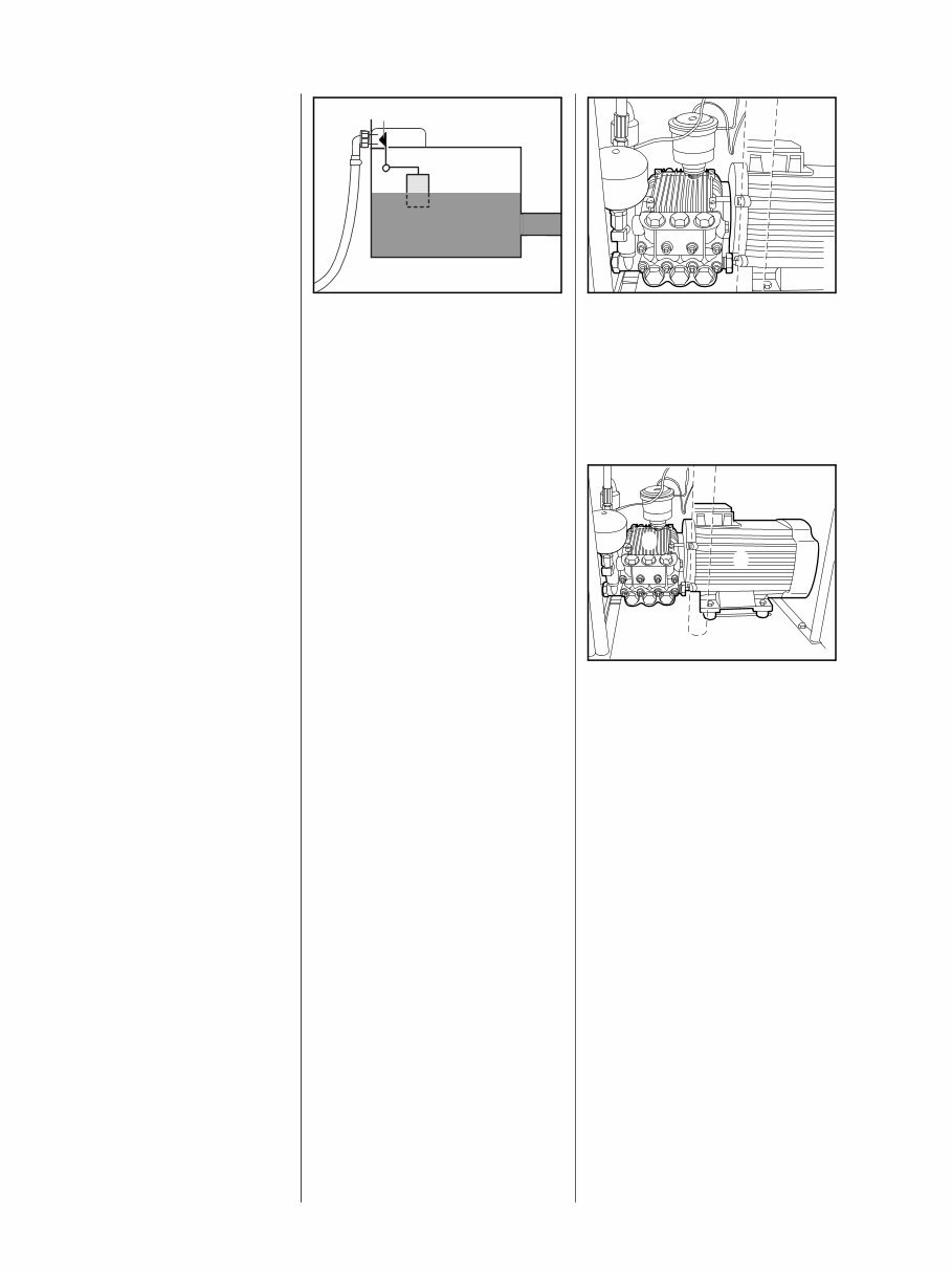
The devices are connected to a
pressurised water network via a
hose coupling.
The water passes through the float-
operated valve (1) into the water
tank. When the water tank is full, the
float-operated valve stops the
inflow.
675RA005 BL
1
At this point, the device is
disconnected from the pressurised
water network; i.e., the water is
prevented from returning into the
water network.
The water is sucked via a hose out
of the water tank through the
strainer into the high-pressure
pump.
From there, it passes through the
regulation valve block and the
heating coil into the heat exchanger
for the high-pressure nozzle.
The interaction between the high-
pressure nozzle and high-pressure
pump (picture) causes the pressure
in the system to rise.
The regulation valve block limits the
pressure to the maximum
permissible value.
675RA006 BL
A three-piston in-line pump with
ceramic pistons is used as the high-
pressure pump (1).
The pump housing is axially flanged
to the electric motor (2). The rotor
shaft is designed hollow and serves
as a pump-side drive shaft for the
pump.
1
2
675RA007 BL
The rotor is mounted on both sides
in 2 roller bearings. This ensures
smooth operation and a long life.
Multi-grade motor oil is used to
lubricate the high-pressure pump.
4. Functional description,
function diagram
4.1 Water conducting system 4.1.1 High-pressure pump
9 RE 521, RE 551, RE 551 PLUS, RE 581, RE 581 PLUS, RE 661, RE 661 PLUS, RE 961, RE 961 PLUS
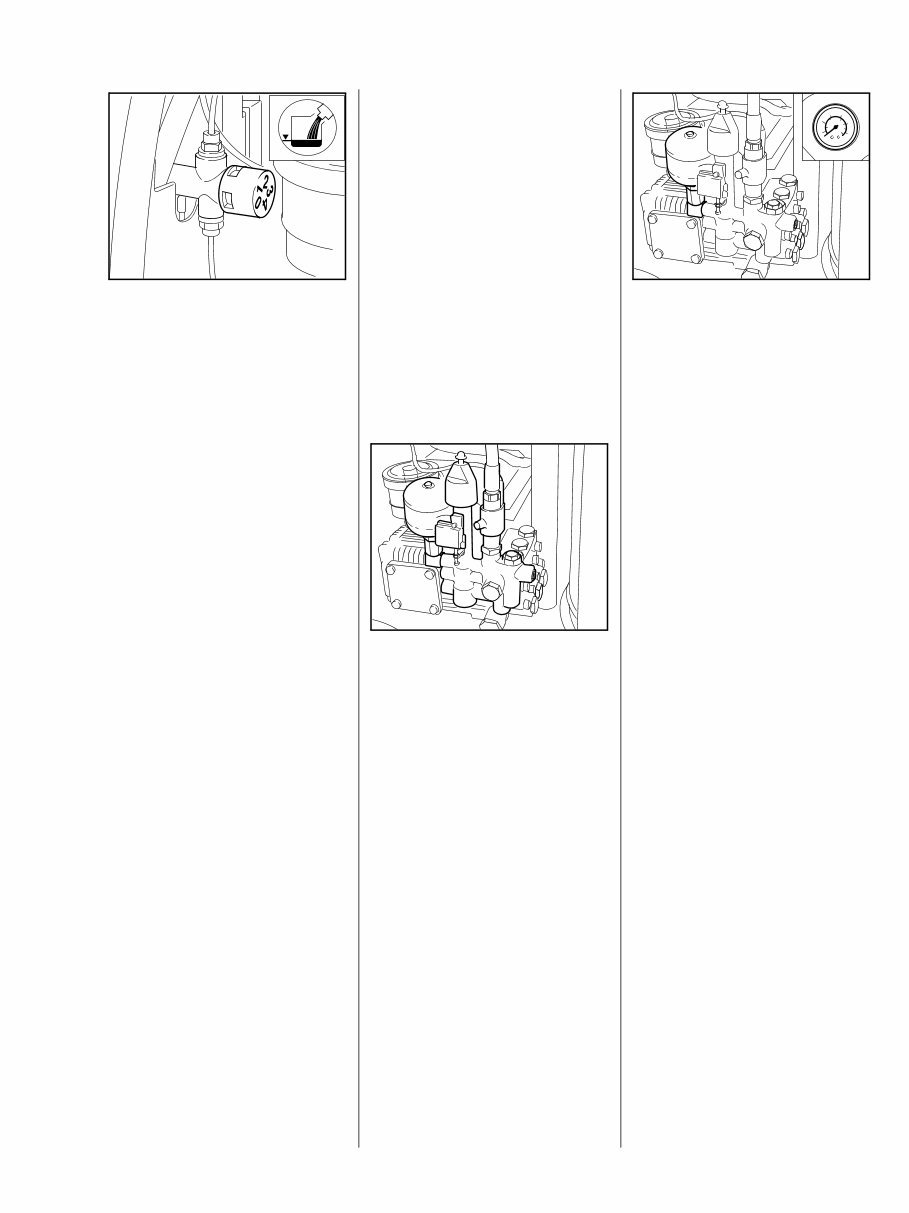
The STIHL hot water high-pressure
cleaners RE 551, RE 581, RE 661
and RE 961 have an automatic
scale inhibitor system. In hot water
mode, concentrated scale inhibitor
drips from the storage tank through
a metering valve (1) into the water
tank. This concentrate prevents
1
675RA302 BL
2
scaling. A control light (2) in the
instrument panel shines when the
concentrated scale inhibitor runs
out in the storage tank.
Under normal conditions, the device
will not have to be descaled when
the STIHL concentrated scale
inhibitor is used properly at the right
dose in hot water mode.
If the operating pressure of the high-
pressure pump exceeds
approximately 5 bar, a bypass valve
opens that connects the pressure
side of the pump to the intake side.
Some of the water flows through
this valve into the intake side.
The bypass valve closes at a
specified pressure depending on
the setting of the control piston
(operating pressure), and the pump
builds up the operating pressure.
When the shut-off pressure of the
regulation valve block is reached (1)
(shut off pressure = operating
pressure + approx. 30 bar) (for
example, when closing the spray
gun), the bypass valve opens
completely, and the start/stop
switch (2) is actuated. The start/stop
1
2
675RA303 BL
switch turns off the electric motor for
the high-pressure pump and the
heating system through the control
electronics.
The pump loses its pressure.
The regulation valve block allows
the device to be controlled with the
spray gun (on/off as well as
pressure level control via the
VarioPress gun).
A pressure gauge (1) and a
hydraulic accumulator (2, only
RE 661 and RE 961) are installed
between the high-pressure pump
and heating coil in the heat
exchanger.
The pressure gauge indicates the
2
675RA304 BL
1
operating pressure of the high-
pressure pump after the regulation
valve block.
The hydraulic accumulator does
three tasks:
1. Suppresses pressure fluctuations
in the high-pressure pump (three
pistons).
2. Suppresses the rise of pressure
from residual heat when the device
is turned off after hot water mode.
3. Suppresses pressure peaks
when turning the spray attachment
on and off.
4.1.2 Automatic scale inhibitor
system
4.1.3 Regulation valve block
You're Reading a Preview
What's Included?
Fast Download Speeds
Online & Offline Access
Access PDF Contents & Bookmarks
Full Search Facility
Print one or all pages of your manual
$27.99
stihl RE 521, RE 551, RE 551 service manual
Viewed 60 Times Today

What's Included?
Fast Download Speeds
Online & Offline Access
Access PDF Contents & Bookmarks
Full Search Facility
Print one or all pages of your manual
$27.99

Secure transaction
What's Included?
Fast Download Speeds
Online & Offline Access
Access PDF Contents & Bookmarks
Full Search Facility
Print one or all pages of your manual
Description
If you are in need of a comprehensive service manual for the Stihl RE 521, RE 551, RE 551 PLUS, RE 581, RE 581 PLUS, RE 661, RE 661 PLUS, RE 961, or RE 961 PLUS, you have come to the right place. These manuals are invaluable resources for both professional mechanics and DIY enthusiasts alike. Whether you are looking to perform routine maintenance or tackle more complex repairs, these manuals provide detailed guidance to help you get the job done efficiently and effectively.


