Onan 25 to 180 kW UR Generators and Controls OEM Service & Repair Manual
What's Included?
Lifetime Access
Fast Download Speeds
Online & Offline Access
Access PDF Contents & Bookmarks
Full Search Facility
Print one or all pages of your manual
Caution: This document contains mixed page sizes (8.5 x 11 or 11 x 17), which may affect printing. Please adjust your printer settings according to the size of each page you wish to print.
Service Manual 25to I80 kW Generators And Controls Troubleshooting and Test Procedures For Generators Regulator Controls 900-0150 10-78 Printed in U.SA
Safety Precautions The following symbols in this manual highlight con- ditions potentially dangerous to service personnel, or equipment. Read this manual carefully. Know when these conditions can exist. Then take necessary steps to protect I WARNING1 personal injury. personnel as well as equipment. equipment damage. This symbol is used throughout the manual to warn of possible serious This symbol refers to possible PROTECT AGAINST MOVING PARTS Avoid moving parts of the unit. Avoid use of loose jackets, shirts or sleeves due to danger of becoming caught in moving parts. Make sure all nuts and bolts are secure. Keep power shields and guards in position. If you must make adjustments while the unit is running, use extreme caution around hot manifolds, moving parts, etc. Do not work on this equipment when mentally or physically fatigued. Y GUARD AGAINST ELECTRIC SHOCK Disconnect electric power before removing protec- tive shields or touching electrical equipment. Use rubber insulative mats placed on dry wood platforms over floors that are metal or concrete when around electrical equipment. Do not wear damp clothing (particularly wet shoes) or allow skin surfaces to be damp when handling electrical equipment. .. Disconnect batteries to prevent accidental engine start. Jewelry is a good conductor of electricity and should be removed before working on electrical equipment. Use extreme caution when working on electrical components. High voltages cause injury or death. Follow all state and local codes. To avoid possible personal injury or equipment damage, a qualified electrician or an authorized service representative must perform installation and all service. EXHAUST GAS IS DEADLY! Exhaust gases contain carbon monoxide, a poisonous gas that might cause unconsciousnessand death. It is an odorless and colorless gas formed during combustion of hydrocarbon fuels. Symptoms of carbon monoxide poisoning are: Dizziness Vomiting Headache Muscular Twitching Weakness and Sleepiness Throbbing in Temples If you experience any of these symptoms, get out into fresh air immediately, shut down the unit and do not use until it has been inspected.. Thebest protection agalnst carbon monoxide inhalation Is proper installallon and regular, frequent visual and audible inspections of the complete exhaust system. If you notice a change in the sound or appearance of exhaust system, shut the unit down immediately and have it inspected and repaired at once by a competent mechanlc.
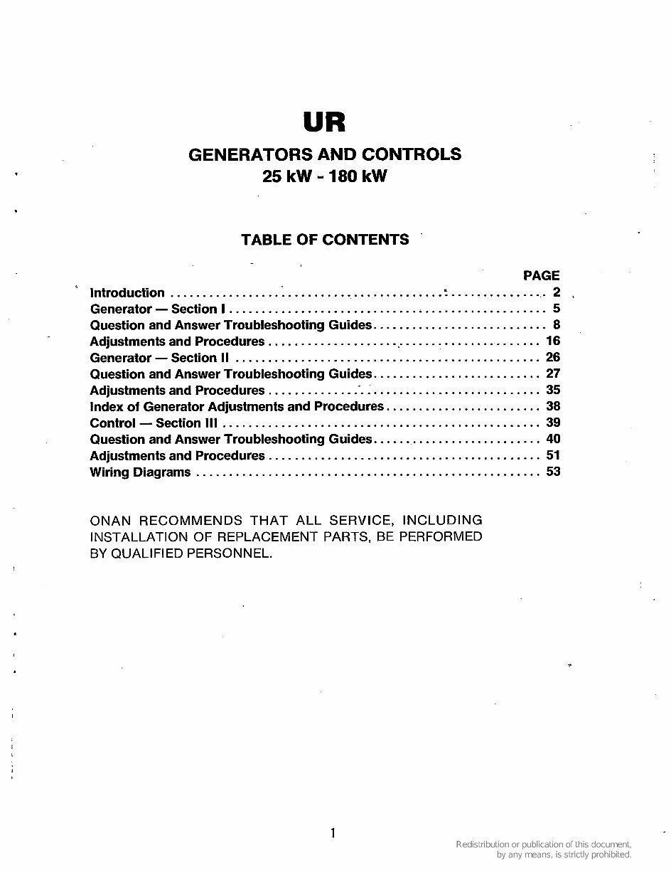
. GENERATORS AND CONTROLS 25 kW - 180 kW TABLE OF CONTENTS ' PAGE ' Introduction .......................................... : ................ 2 . Generator - Section I ................................................. 5 Question and Answer Troubleshooting Guides. .......................... 8 Adjustments and Procedures ............................................ 16 Generator - Section II ............................................... 26 Question and Answer Troubleshooting Guides. ......................... 27 Adjustments and Procedures ........................................... 35 Index of Generator Adjustments and Procedures. ....................... 38 Control - Section 111 ................................................. 39 Question and Answer Troubleshooting Guides. ......................... 40 Adjustments and Procedures .......................................... 51 Wiring Diagrams ..................................................... 53 . I I ONAN RECOMMENDS THAT ALL SERVICE, INCLUDING INSTALLATION OF REPLACEMENT PARTS, BE PERFORMED BY QUALIFIED PERSONNEL. I
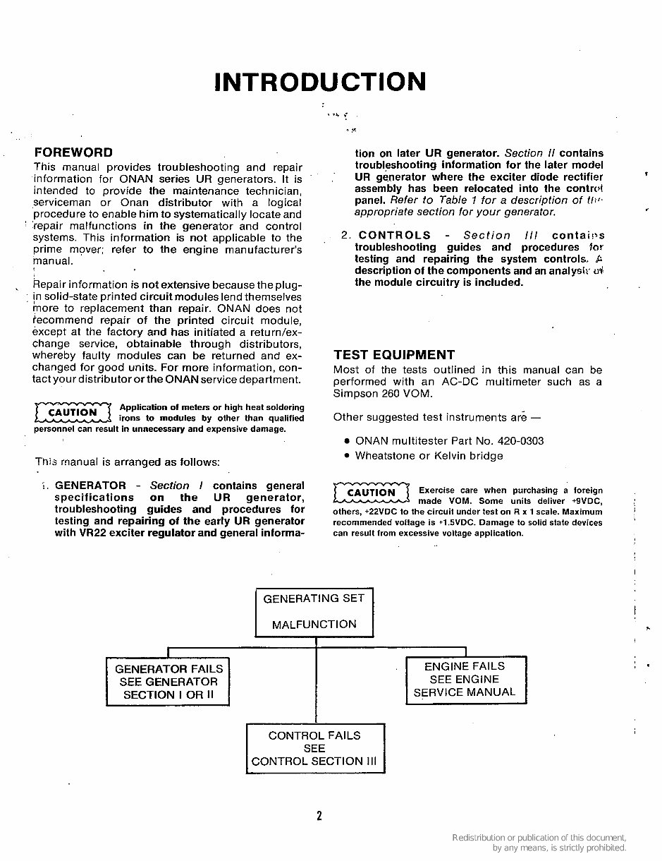
I NTRO DU CTIO N FOREWORD This manual provicds troubleshooting and repair information for ONAN series UR generators. It is intended to provide the maintenance technician, serviceman or Onan distributor with a logical procedure to enable him to systematically locate and ' 'repair malfunctions in the generator and control systems. This information is not applicable to the prime mover; refer to the engine manufacturer's manual. Repair information is not extensive because the plug- in solid-state printed circuit modules lend themselves more to replacement than repair. ONAN does not recommend repair of the printed circuit module, except at the factory and has initiated a returdex- change service, obtainable through distributors, whereby faulty modules can be returned and ex- changed for good units. For more information, con- tact your distributororthe ONAN service department. , Application of meters or high heat soldering irons to modules by other than qualified personnel can result in unnecessary and expensive damage. This rnanual is arranged as follows: i. GENERATOR - Section I contains general specifications on the UR generator, troubleshooting guides and procedures for testing and repairing of the early UR generator with VR22 exciter regulator and general informa- tion on later UR generator. Section 11 contains troubleshooting information for the later model UR generator where the exciter diode rectifier assembly has been relocated into the contrd panel. Refer to Table 1 for a description of t/:f. appropriate section for your generator. 2. CONTROLS - Section 111 contai!$s troubleshooting guides and procedures lor testing and repairing the system controls, P description of the components and an analysiz' ti+ the module circuitry is included. TEST EQUIPMENT Most of the tests outlined in this manual can be performed with an AC-DC multimeter such as a Simpson 260 VOM. Other suggested test instruments are - ONAN multitester Part No. 420-0303 Wheatstone or Kelvin bridge Exercise care when purchasing a foreign made VOM. Some units deliver +9VDC, others, +22VDC to the circuit under test on R x 1 scale. Maximum recommended voltage is +l.SVDC. Damage to solid state devices can result from excessive voltage application. GENERATING SET MALFUNCTION GENERATOR FAILS SEE GENERATOR SECTION I OR II ENGINE FAILS SEE ENGINE I SERVICE MANUAL I I ' CONTROL FAILS CONTROL SECTION Ill 2
TABLE 1. GENERATOR SPECIFICATION BREAKDOWN kW Model 25.0 EK 30.0 EK Penn EK 25.0 DDA 30.0 DDB 30.0 DEH 25.0 MDEH 30.0 MDEH Penn DEH 37.5 EM 45.0 EM Penn EM 37.5 DEF 45.0 DEF Penn DEF 37.5 DYJ 45.0 DYJ 40.0 DDB 50.0 DDB 40.0 DEG 50.0 DEG Penn DEG 40.0 MDEG 50.0 MDEG 45.0 KB 55.0 KB Penn KB 50.0 DYA 60.0 DYA Penn DYA 55.0 EN 70.0 EN 50 Hz 60 Hz 50 Hz 60 Hz 60 Hz 50 Hz 60 Hz 50 Hz 60 Hz 50 Hz 60 Hz 50 Hz 60 Hz 50 Hz 60 Hz 50 Hz 60 Hz 50 Hz 60 Hz 50 Hz 60 Hz 50 Hz 60 Hz 60 Hz 60 Hz E D E - - D D C E E D E H F G - - - - G E F F E R P Q E C D - - Section 1 Spec A Frequency Section 2 Begin Spec F F F A A G G G G F F F J J J A A A A H H H H H S S S F F F A A kW Model 55.0 KB 55.0 KB "enn KB 50.0 DYC 75.0 DYC 30.0 DYC 100.0 DYC 'enn DYC 70.0 KR 35.0 KR Penn KR 75.0 DYC 30.0 DYC 30.0 DYD 100.0 DYD Penn DYD 35.0 WA 11 5.0 WA 100.0 DYD 125.0 DYD Penn DYD 115.0 WE 140.0 WE 125.0 WE 150.0 WE 125.0 DYG 150.0 DYG Penn DYG 130.0 DFE 155.0 DFE Penn DFE 140.0 WB 170.0 WB 145.0 DYG 175.0 DYG Penn DYG 150.0 DFE 180.0 DFE Penn DFE Section 1 Spec A Frequency 1 ThN ' 50 Hz 60 Hz 50 Hz 60 Hz 50Hz ' 60 Hz 50 Hz 60 Hz 50 Hz 60 Hz 50 Hz 60 Hz 50 Hz 60 Hz 50 Hz 60 Hz 50 Hz 60 Hz 50 Hz 60 Hz 50 Hz- 60'HZ 50 Hz 60 Hz 50 Hz 60 Hz 50 Hz 60 Hz 50 Hz 60 Hz R P Q D B - - j c R P Q D B C A B H G C A B B B B B C A B - - - K J C A B - - - Section 2 Begin Spec S S S E E G G 'E S S S E E .D D D J J D D D - - - - D D D H H H L L D D D H H H 3
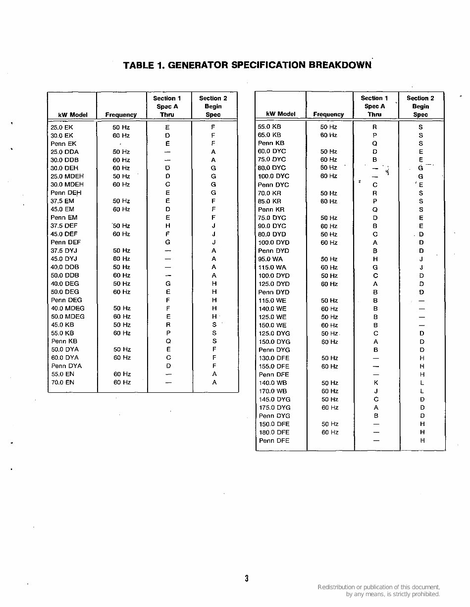
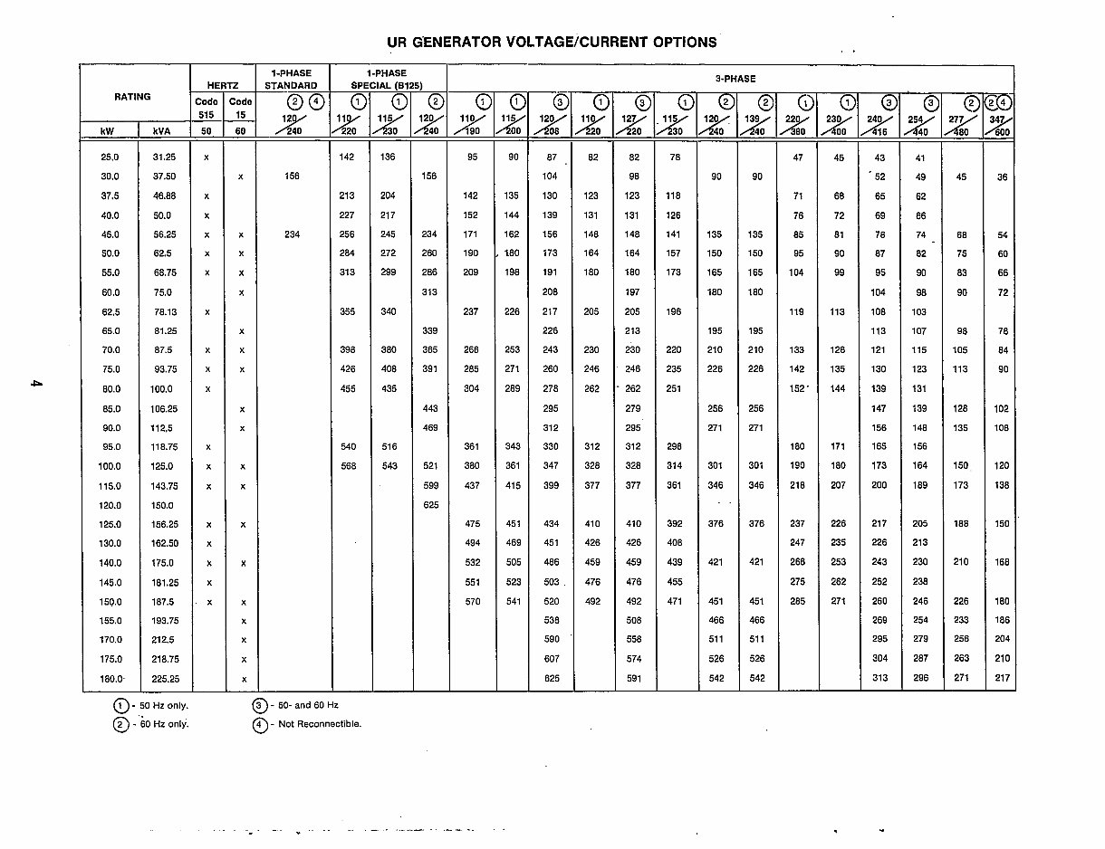
UR G’ENERATOR VOLTAGE/CURRENT OPTIONS 1-PHASE 3-PHASE 1-PHASE STANDARD @@ 2K 156 234 I_ :ode 15 60 - - - X X X X X X X X X X X X X X X X X X X - HE :ode 50 - 515 - - X X X X X X X X X X X X X X X X X X - SPE - 0 g - 142 213 227 256 284 313 355 398 426 455 540 568 L 0 - 156 234 260 286 313 339 365 391 443 469 521 599 625 RATING - c g - 90 135 144 162 180 198 226 253 271 289 343 361 415 451 469 505 523 541 - 0 g - 82 123 131 148 164 180 205 230 246 262 312 328 377 41 0 426 459 476 492 - 0 g - 78 118 126 141 157 173 196 220 235 251 298 314 361 392 408 439 455 471 - @ g - 90 135 150 165 180 195 210 226 256 271 301 346 376 421 451 466 51 1 526 542 - g - 47 71 76 85 95 104 119 133 142 152 ’ 180 190 218 237 247 266 275 285 - c - 95 142 152 171 190 209 237 266 285 304 361 380 437 475 494 532 551 570 - 0 - 82 98 123 131 148 164 180 197 205 213 230 246 262 279 295 312 328 377 410 426 459 476 492 508 558 574 591 - c - 45 68 72 81 90 99 113 126 135 144 171 180 207 226 235 253 262 271 - E - 43 . 52 65 69 78 87 95 104 108 113 121 130 139 147 156 165 173 200 217 226 243 252 260 269 295 304 313 - E g - 45 68 75 83 90 98 105 113 128 135 150. 173 188 210 226 233 256 263 271 - E - 41 49 62 66 74 82 90 98 103 107 115 123 131 139 148 156 164 189 205 213 230 238 246 254 279 287 296 a g - 136 204 217 245 272 299 340 380 408 435 516 543 0 - E7 . 104 130 139 156 173 191 208 217 226 243 260 278 295 312 330 347 399 434 451 486 503 520 538 590 607 625 g - 90 135 150 165 180 195 210 226 256 27 1 301 346 -. 376 42 1 451 466 51 1 526 542 k y 600 - - 36 54 60 66 72 78 84 90 102 108 120 138 150 168 180 186 204 210 217 - kW 25.0 30.0 37.5 40.0 45.0 50.0 55.0 60.0 62.5 65.0 70.0 75.0 80.0 85.0 90.0 95.0 100.0 115.0 120.0 125.0 130.0 140.0 145.0 150.0 155.0 170.0 175.0 180.0. kVA 31.25 37.50 46.80 50.0 56.25 62.5 68.75 75.0 78.13 81.25 87.5 93.75 100.0 106.25 112,5 11 8.75 125.0 143.75 150.0 156.25 162.50 175.0 181.25 187.5 193.75 212.5 218.75 225.25 4 0 - , : o HZ only. @ - 60 Hz only. @ - 50- and 60 Hz @ - Not Reconnectible. . . . . . - . . .. .. -.
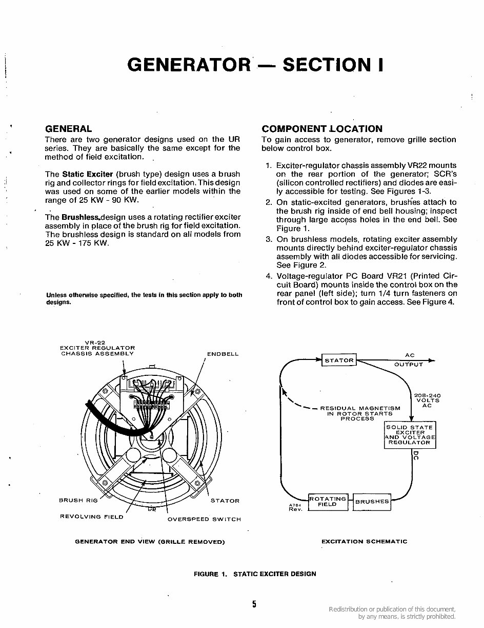
GENERATOR v GENERAL There are two generator designs used on the UR series. They are basically the same except for the method of field excitation. , The Static Exciter (brush type) design uses a brush rig and collector rings for field excitation. This design was used on some of the earlier models within the range of 25 KW - 90 KW. The Brushlessdesign uses a rotating rectifier exciter assembly in place of the brush rig for field excitation. The brushless design is standard on all models from 25 KW - 175 KW. . Unless otherwise specified, the tests in this section apply to both designs. V R -22 EXCITER REGULATOR CHASSIS ASSEMBLY END B ELL .TOR - SECTION I COMPONENT LOCATION To gain access to generator, remove grille section below control box. 1. 2. 3. 4. Exciter-regulator chassis assembly VR22 mounts on the rear portion of the generator; SCR’s (silicon controlled rectifiers) and diodes are easi- ly accessible for testing. See Figures 1-3. On static-excited generators, brush”es attach to the brush rig inside of end bell housing; inspect through large access holes in the end bell. See Figure 1. On brushless models, rotating exciter assembly mounts directly behind exciter-regulator chassis assembly with all diodes accessible for servicing. See Figure 2. Voltage-regulator PC Board VR21 (Printed Cir- cuit Board) mounts inside the control box on the rear panel (left side); turn 114 turn fasteners o,n front of control box to gain access. See Figure 4. AC STATOR L OUTPUT - 208-240 VOLTS ‘\-- RESIDUAL MAGNETISM AC IN ROTOR STARTS PROCESS , & ~ SOLID STATE 4ND VOLTAGE REGULATOR REVOLVING FIELD OVERSPEED SWITCH QENERATOR END VIEW (QRILLE REMOVED) EXCITATION SCHEMATIC FIGURE 1. STATIC EXCITER DESIGN 5
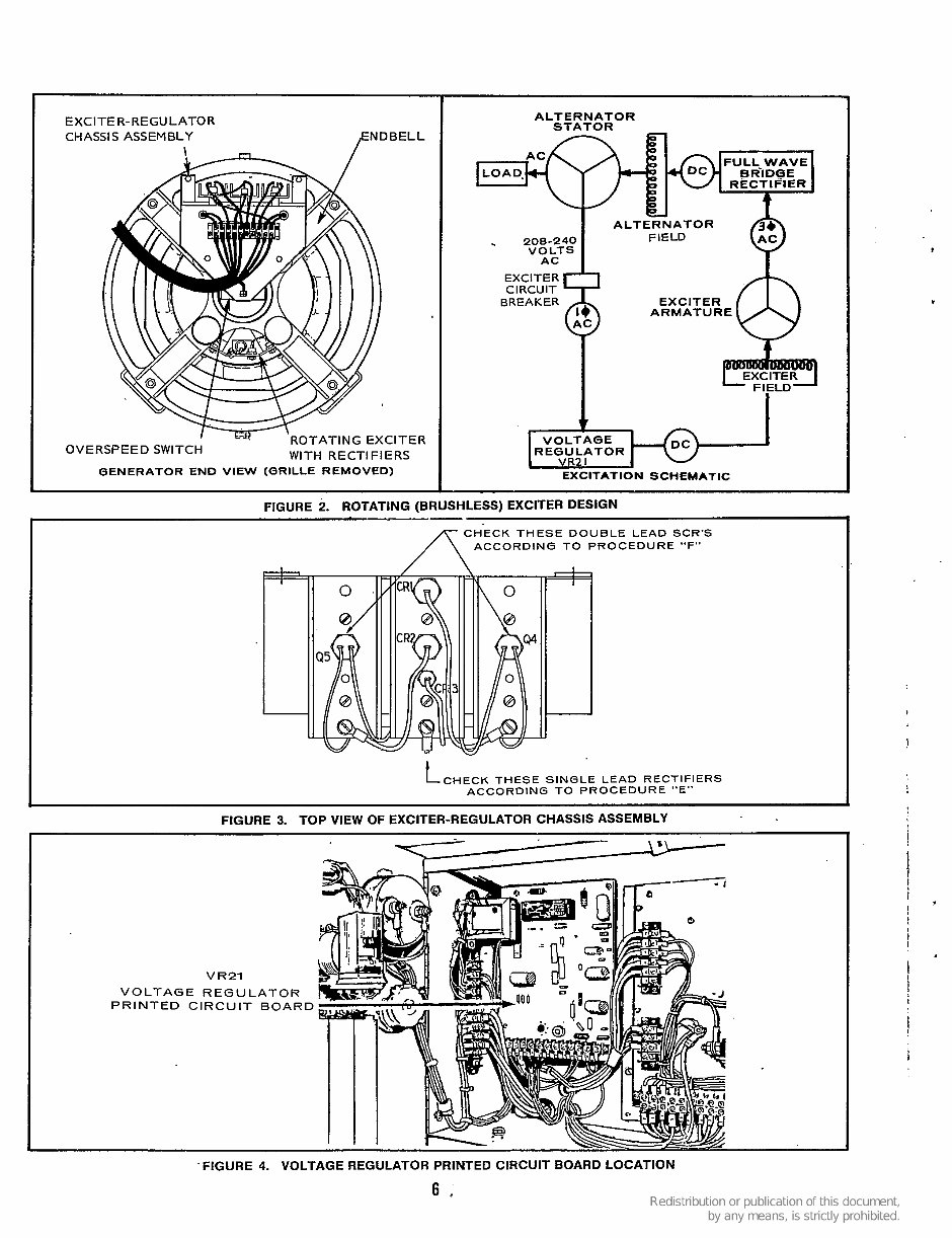
EXClTE R- REGULATO R CHASSIS ASSEMBLY FENDBELL QENERATOR END VIEW (QRILLE REMOVED) I A LT ERNAT0 R iTATOR w FIELD I . 208-240 VOLTS AC EXCITER CIRCUIT BREAKER EXCITER ARMATURE VOLTAGE R E(3U LATOR ~~~ EXCITATION SCHEMATIC t CHECK THESE SINGLE LEAD RECTIFIERS ACCORDING TO PROCEDURE "E" FIGURE 3. TOP VIEW OF EXCITER-REGULATOR CHASSIS ASSEMBLY V R21 VOLTAGE REGULATOR PRINTED CIRCUIT BOARD , ! ! i 'FIGURE 4. VOLTAGE REGULATOR PRINTED CIRCUIT BOARD LOCATION 6,
I I VISUAL INSPECTION Before proceeding with the troubleshooting on the following pages, a few simple checks can be made which could directly indicate the cause'of trouble. 1. Always be sure that connection of generator leads is correct. Whenever leads are reconnected for a different voltage, check the output with an independent voltmeter. Do not use the control panel meter since it could indicate that the voltage is correct even if connection is wrong. 2. Visually inspect the voltage regulator printed circuit board assembly (VR21) in the control box for burned components, broken wires, loose connections, dust, dirt or moisture. If dirty, clean with a suitable solvent and compressed air. 3. Visually inspect the exciter-regulator chassis assembly (VR22) for burned components, broken wires, loose connections, carbon tracks caused by arcing between parts or between parts and ground. Also check for shorted paths between terminals caused by dust, dirt and moisture. 4. Large banks of SCR (Silicon Controlled Rectifier) regulated loads can cause the generator voltage to increase as load is applied. If such loads exist, and the voltage increased more than 5 or lo%, consult the factory; an additional filter is available for the regulator circuit to correct the situation. THE QUESTION AND ANSWER TROUBLESHOOTING GUIDES BEGINNING ON PAGE 8 GIVE A STEP-BY-STEP PROCEDURE FOR CHECKING THE GENERATOR. THE FLOW-CHART TROUBLESHOOTING GUIDES ARE GIVEN AS A GENERAL GUIDE TO RESOLVE VARIOUS GENERATOR PROBLEMS. ALL CHARTS REFER TO PROCEDURESSHOWN AT THE END OF THIS SECTION. . PRIOR TO ANY TROUBLESHOOTING, CHECK ALL MODIFICATIONS, REPAIRS, REPLACEMENTS, ETC.. PERFORMED SINCE LAST SATISFAC- TORY OPERATION OF SET. 7
The Onan Cummins UR Series Generators Service Repair Manual is a comprehensive workshop manual that provides detailed servicing instructions for your Onan Cummins Generator. This manual includes complete information on repair, servicing, preventative maintenance, and troubleshooting procedures. It features step-by-step instructions, photos, and illustrations to guide you through the entire repair process, making it an indispensable resource for both professional mechanics and DIY enthusiasts.
This manual covers UR 25 to 180 kW Generators and offers easy navigation for quick access to service repair procedures. It includes detailed illustrations, exploded diagrams, drawings, and photos to assist with every service repair procedure.
File Format: PDF
Pages: 79
Printable: Yes
Language: English
Subjects covered in this manual include:
ENGINE AND ACCESSORIES
Major Engine Service
Engine Sensors
Governor Actuator
Exhaust Manifold
Fuel System
Starter
Battery Charging Alternator
GENERATOR
Testing Generator
Disassembly
Reassembly
Reconnecting the Generator
Line Circuit Breakers
SAFETY PRECAUTIONS
CONTROL PANEL
OPERATION
Engine Oil Recommendations
Engine Coolant
Line Circuit Breakers PERIODIC MAINTENANCE
Checking Engine Oil Level
Changing Engine Oil and Filter
Draining/Replacing Fuel Filters
Maintaining the Engine Cooling System
GENERATOR SET CONTROL
DC Circuit Breaker
Engine Oil Pressure Sender
Engine Coolant Temperature Sender
Governor Actuator
Starter Relay
SPECIFICATIONS
WIRING DIAGRAM
Upon purchasing this Onan Cummins UR Series Service Manual Generator Repair Book, you will receive instant access to the PDF format. The manual is fully printable, allowing you to print pages whenever needed.
Recently Viewed
5,521,897Happy Clients
2,594,462eManuals
1,120,453Trusted Sellers
15Years in Business
Price:
Actual Price:
Onan 25 to 180 kW UR Generators and Controls OEM Service & Repair Manual